Lexus LS (2023 year). Manual in english - page 9
 

  Index      Manuals     Lexus LS (2023 year). Manual in english


Search            copyright infringement  


Content      ..     7      8      9      10     ..


Lexus LS (2023 year). Manual in english - page 9


290

4-5. Using the driving support systems

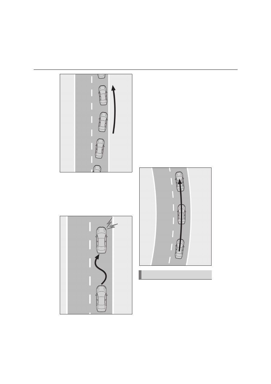
Vehicle sway warning function

When the vehicle is swaying within a 
lane, the warning buzzer will sound and 
a message will be displayed on the 
multi-information display to alert the 
driver.

Lane centering function

This function is linked with dynamic 
radar cruise control with full-speed 
range and provides the required assis-
tance by operating the steering wheel 
to keep the vehicle in its current lane.

When dynamic radar cruise control with 
full-speed range is not operating, the lane 
centering function does not operate.
In situations where the white (yellow) lane 
lines are difficult to see or are not visible, 
such as when in a traffic jam, this function 
will operate to help follow a preceding 
vehicle by monitoring the position of the 
preceding vehicle.

Turning the LTA system on

Press the LTA switch.

When the LTA system will turn on, the LTA 
indicator will illuminate and a message will 
be displayed on the multi-information dis-

LTA system setting

291

4

4-5. Using the driving support systems

Driving

play.
Also, the lane centering function will 
change between on/off each time the 
switch is pressed.

Lane centering function off: “LTA Steering 
Assist Active” is displayed.
Lane centering function on: “LTA Steering 
Assist Active Lane centring Active” is dis-
played.
When the LTA system is turned on, opera-
tion of the LTA system continues in the 
same condition the next time the hybrid 
system is started.

Turning the LTA system off

Press and hold the LTA switch.

The LTA indicator light turns off when the 
LTA is turned off.
When the LTA system is turned off, opera-
tion of the LTA system continues in the 
same condition the next time the hybrid 
system is started.

LTA indicator

The illumination condition of the indicator 
informs the driver of the system operation 
status.
Illuminated in white: LTA system is operat-
ing.
Illuminated in green: Steering wheel assis-
tance of the steering assist function or lane 
centering function is operating.
Flashing in orange: Lane departure alert 
function is operating.

Operation display of steering 
wheel operation support

Displayed when the multi-information dis-
play is switched to the driving support sys-
tem information display.
Indicates that steering wheel assistance of 
the steering assist function or lane center-
ing function is operating.
Both outer sides of the lane are displayed: 
Indicates that steering wheel assist of the 
lane centering function is operating.
One outer side of the lane is displayed: 
Indicates that steering wheel assist of the 
steering assist function is operating.
Both outer sides of the lane are flashing: 
Alerts the driver that their input is neces-
sary to stay in the center of the lane (lane 

Indications on multi-information 
display

A

B

292

4-5. Using the driving support systems

centering function).

Lane departure alert function dis-
play

Displayed when the multi-information dis-
play is switched to the driving support sys-
tem information display.

Inside of displayed lines is white

Indicates that the system is recognizing 
white (yellow) lines or a course

*

. When 

the vehicle departs from its lane, the 
white line displayed on the side the 
vehicle departs from flashes orange.

Inside of displayed lines is black

Indicates that the system is not able to 
recognize white (yellow) lines or a 
course

*

 or is temporarily canceled.

*

: Boundary between asphalt and the side 

of the road, such as grass, soil, or a curb

Follow-up cruising display

Displayed when the multi-information dis-

play is switched to the driving support sys-
tem information display.
Indicates that steering assist of the lane 
centering function is operating by monitor-
ing the position of a preceding vehicle.
When the follow-up cruising display is dis-
played, if the preceding vehicle moves, 
your vehicle may move in the same way. 
Always pay careful attention to your 
surroundings and operate the steering 
wheel as necessary to correct the path of 
the vehicle and ensure safety.

Operation conditions of each function

Lane departure alert function

This function operates when all of the fol-

lowing conditions are met.

• LTA is turned on.

• Vehicle speed is approximately 50 km/h 

(32 mph) or more.

*1

• System recognizes white (yellow) lane 

lines or a course

*2

. (When a white [yel-

low] line or course

*2

 is recognized on 

only one side, the system will operate 

only for the recognized side.)

• Width of traffic lane is approximately 3 m 

(9.8 ft.) or more.

• Turn signal lever is not operated. (Vehicle 

with BSM: Except when another vehicle 

is in the lane on the side where the turn 

signal was operated)

• Vehicle is not being driven around a 

sharp curve.

• No system malfunctions are detected. 

(

P.294)

*1

: The function operates even if the vehi-

cle speed is less than approximately 50 
km/h (32 mph) when the lane center-
ing function is operating.

*2

: Boundary between asphalt and the side 

of the road, such as grass, soil, or a curb

Steering assist function

This function operates when all of the fol-

lowing conditions are met in addition to the 

operation conditions for the lane depar-

C

D

293

4

4-5. Using the driving support systems

Driving

ture alert function.

• Vehicle is not accelerated or decelerated 

by a fixed amount or more.

• Steering wheel is not operated with a 

steering force level suitable for changing 

lanes.

• ABS, VSC, TRC and PCS are not oper-

ating.

• TRC or VSC is not turned off.

Vehicle sway warning function

This function operates when all of the fol-

lowing conditions are met.
• Setting for “Sway Warning” in 

 of the 

multi-information display is set to “ON”. 

(

P.114)

• Vehicle speed is approximately 50 km/h 

(32 mph) or more.

• Width of traffic lane is approximately 3 m 

(9.8 ft.) or more.

• No system malfunctions are detected. 

(

P.294)

Lane centering function

This function operates when all of the fol-

lowing conditions are met.

• LTA is turned on.
• Setting for “Lane Centre” in 

 of the 

multi-information display is set to “ON”. 

(

P.114)

• This function recognizes white (yellow) 

lane lines or the position of a preceding 

vehicle (except when the preceding vehi-

cle is small, such as a motorcycle).

• The dynamic radar cruise control with 

full-speed range is operating in vehi-

cle-to-vehicle distance control mode.

• Width of traffic lane is approximately 3 to 

4 m (10 to 13 ft.).

• Turn signal lever is not operated.

• Vehicle is not being driven around a 

sharp curve.

• No system malfunctions are detected. 

(

P.294)

• Vehicle does not accelerate or 

decelerate by a fixed amount or more.

• Steering wheel is not operated with a 

steering force level suitable for changing 

lanes.

• ABS, VSC, TRC and PCS are not oper-

ating.

• TRC or VSC is not turned off.

• Hands off steering wheel warning is not 

displayed. (

P.294)

• The vehicle is being driven in the center 

of a lane.

• Steering assist function is not operating.

Temporary cancelation of functions

When operation conditions are no longer 

met, a function may be temporarily 

canceled. However, when the operation 

conditions are met again, operation of the 

function is automatically restored. 

(

P.292)

If the operation conditions (

P.292) are 

no longer met while the lane centering 

function is operating, the steering wheel 

may vibrate and the buzzer may sound to 

indicate that the function has been tem-

porarily canceled. However, if the “Alert” 
customization setting is set to 

the system will notify the driver by vibrat-

ing the steering wheel instead of sound-

ing the buzzer.

Steering assist function/lane centering 

function

Depending on the vehicle speed, lane 

departure situation, road conditions, etc., 

the driver may not feel the function is 

operating or the function may not oper-

ate at all.

The steering control of the function is 

overridden by the driver’s steering wheel 

operation.

Do not attempt to test the operation of 

the steering assist function.

Lane departure alert function

The warning buzzer may be difficult to 

hear due to external noise, audio play-

back, etc. Also, it may be difficult to feel 

steering wheel vibrations due to the road 

conditions, etc.

If the edge of the course

*

 is not clear or 

straight, the lane departure alert function 

may not operate.

Vehicle with BSM: It may not be possible 

for the system to determine if there is a 

danger of a collision with a vehicle in an 

adjacent lane.

294

4-5. Using the driving support systems

Do not attempt to test the operation of 

the lane departure alert function.

*

: Boundary between asphalt and the side 

of the road, such as grass, soil, or a curb

Hands off steering wheel warning

In the following situations, a warning mes-

sage urging the driver to hold the steering 

wheel and the symbol shown in the illustra-

tion are displayed on the multi-information 

display to warn the driver. The warning 

stops when the system determines that the 

driver holds the steering wheel. Always 

keep your hands on the steering wheel 

when using this system, regardless of warn-

ings.

When the system determines the driver is 

not holding the steering wheel while the 

lane centering function is operating.

If the driver continues to keep their hands 
off of the steering wheel, the buzzer 
sounds, the driver is warned and the func-
tion is temporarily canceled. This warning 
also operates in the same way when the 
driver continuously operates the steering 
wheel only a small amount.
The buzzer also sounds even if the alert 
type is set to 

.

When the system determines that the 

vehicle may deviate from the lane while 

driving around a curve while the lane 

centering function is operating.

When the system determines that the 

driver is driving without holding the steer-

ing wheel while the steering wheel assist 

of the steering assist function is operating

If the driver continues to keep their hands 
off of the steering wheel and the steering 

wheel assist is operating, the buzzer 
sounds and the driver is warned. Each time 
the buzzer sounds, the continuing time of 
the buzzer becomes longer.
The buzzer also sounds even if the alert 
type is set to 

.

Vehicle sway warning function

When the system determines that the vehi-

cle is swaying while the vehicle sway warn-

ing function is operating, a buzzer sounds 

and a warning message urging the driver to 

rest and the symbol shown in the illustration 

are simultaneously displayed on the 

multi-information display.

Depending on the vehicle and road condi-

tions, the warning may not operate.

Warning message

If the following warning message is dis-

played on the multi-information display and 

the LTA indicator illuminates in orange, fol-

low the appropriate troubleshooting proce-

dure. Also, if a different warning message is 

displayed, follow the instructions displayed 

on the screen.

“LTA Malfunction Visit Your Dealer”

The system may not be operating properly. 

Have the vehicle inspected by any author-

ized Lexus retailer or Lexus authorized 

repairer, or any reliable repairer.

“LTA Unavailable”

The system is temporarily canceled due to 

a malfunction in a sensor other than the 

front camera. Turn the LTA system off, wait 

for a little while, and then turn the LTA sys-

tem back on.

“LTA Unavailable at Current Speed”

The function cannot be used as the vehicle 

295

4

4-5. Using the driving support systems

Driving

speed exceeds the LTA operation range. 

Drive slower.

Customization

Function settings can be changed. 

(Customizable features:

P.540)

*

: If equipped

The RSA system recognizes specific 
road signs using the front camera 
and/or navigation system (when speed 
limit information is available) to provide 
information to the driver via the display.

If the system judges that the vehicle is 
being driven over the speed limit, per-
forming prohibited actions, etc. 
according to the recognized road 
signs, it notifies the driver through a 
visual notification and notification 
buzzer or steering wheel vibration.

RSA (Road Sign Assist)

*

Summary of function

WARNING

Before using the RSA

Do not rely solely upon the RSA system. 

RSA is a system which supports the 

driver by providing information, but it is 

not a replacement for a driver’s own 

vision and awareness. Drive safely by 

always paying careful attention to the 

traffic rules.

296

4-5. Using the driving support systems

When the front camera recognizes a 
sign and/or information of a sign is 
available from the navigation system, 
the sign will be displayed on the 
multi-information display.

When the Driving support system 
information display is selected, a 
maximum of 3 signs can be dis-
played. (

P.114)

When a tab other than the Driving 
support system information display 
is selected, the following types of 
road signs will be displayed. 
(

P.114)

• Speed limit begins/ends sign
• Speed limit related information sign 

(Motorway, Expressway, Urban area, 
Residential area)

• End of prohibition sign

• No-entry  sign

*

 (when notification is nec-

essary)

• Speed limit with supplemental sign 

(Ramp way only)

*

: For vehicles with navigation system

If signs other than speed limit signs are rec-
ognized, they will be displayed in an over-
lapping stack under the current speed limit 
sign.

The following types of road signs, 
including electronic signs and blinking 
signs, are displayed.

A non-official (not meeting the Vienna 
Convention) or a recently introduced traf-
fic sign may not be displayed.

Speed limit road signs

*

*

: No speed limit information 

 is dis-

played when neither speed limit road 
sign nor speed limit related information 
is available.

Speed limit related information

*1,2

Indication on the multi-informa-
tion display

Supported types of road signs

Speed limit begins/Maximum 
speed zone begins

Speed limit ends/Maximum 
speed zone ends

297

4

4-5. Using the driving support systems

Driving

*1

: Displayed when a sign is recognized 

but speed limit information for the road 
is not available from the navigation sys-
tem

*2

: No speed limit information 

 is dis-

played when neither speed limit road 
sign nor speed limit related information 
is available.

No-overtaking road signs

Other road signs

*

: For vehicles with navigation system

Speed limit with supplemental 
mark

*1

*1

: Displayed simultaneously with speed 

limit.

*2

: Contents not recognized.

*3

: If the turn signal indicator is not oper-

Motorway entrance

Motorway exit

Expressway entrance

Expressway exit

Urban area beginning

Urban area ending

Urban area beginning

Urban area ending

Residential area beginning

Residential area ending

No overtaking begins

No overtaking ends

No-entry

*

End of prohibition

Stop

Wet

Rain

Ice

Supplemental mark exists

*2

Exit ramp on right

*3

Exit ramp on left

*3

Time

298

4-5. Using the driving support systems

ated when changing lanes, the mark 
does not display.

In the following situations, the RSA sys-
tem will notify the driver.

When the vehicle speed exceeds 
the speed notification threshold of 
the speed limit sign displayed, the 
sign display will be emphasized and 
a buzzer will sound.

When the RSA system recognizes a 
no-entry sign and detects that the 
vehicle has entered a no-entry area 
based on the map information of the 
navigation system, the no-entry sign 
flashes and a buzzer will sound. (For 
vehicles with navigation system)

If it is detected that your vehicle is 
overtaking when a no overtaking 
sign is displayed on the multi-infor-
mation display, the displayed sign 
will flash and a steering wheel will 
vibrate.

Depending on the situation, traffic 
environment (traffic direction, speed 
unit) may be detected incorrectly and a 
notification function may not operate 
properly.

Setting procedure

1

Press 

 or 

 of the meter control 

switches and select 

.

2

Press 

 or 

 of the meter control 

switches and select “Vehicle Settings”, 
then press 

.

3

Press 

 or 

 of the meter control 

switches and select 

, then press 

.

4

Press 

 or 

 of the meter control 

switches and select “RSA”, then press 

.

Automatic turn-off of RSA sign display

One or more signs automatically turn off in 

the following situations.

No sign has been recognized for a cer-

tain distance.

The road changes due to a left or right 

turn, etc.

Conditions in which the function may 

not operate or detect correctly

In the following situations, RSA does not 

operate normally and may not recognize 

signs, display the incorrect sign, etc. How-

ever, this does not indicate a malfunction.

The front camera is misaligned due to a 

strong impact being applied to the sen-

sor, etc.

Dirt, snow, stickers, etc. are on the wind-

shield near the front camera.

In inclement weather such as heavy rain, 

fog, snow or sand storms.

Light from an oncoming vehicle, the sun, 

etc. enters the front camera.

The sign is dirty, faded, tilted or bent.

The contrast of electronic sign is low.

All or part of the sign is hidden by the 

leaves of a tree, a pole, etc.

The sign is only visible to the front camera 

for a short amount of time.

The driving scene (turning, lane change, 

etc.) is judged incorrectly.

If a sign not appropriate for the currently 

traveled lane, but the sign exists directly 

after a freeway branches, or in an adja-

cent lane just before merging.

Stickers are attached to the rear of the 

preceding vehicle.

Notification function

299

4

4-5. Using the driving support systems

Driving

A sign resembling a system compatible 

sign is recognized.

Side road speed signs may be detected 

and displayed (if positioned in sight of the 

front camera) while the vehicle is 

traveling on the main road.

Roundabout exit road speed signs may 

be detected and displayed (if positioned 

in sight of the front camera) while 

traveling on a roundabout.

The front of the vehicle is raised or low-

ered due to the carried load.

The surrounding brightness is not suffi-

cient or changes suddenly.

When a sign intended for trucks, etc. is 

recognized.

The vehicle is driven in a country with a 

different direction of traffic.

The navigation system map data is out-

dated.

The navigation system is not operating.

The speed information displayed on the 

meter and on the navigation system may 

be different due to the navigation system 

using map data.

Speed limit sign display

If the power switch was last turned off while 

a speed limit sign was displayed on the 

multi-information display, the same sign dis-

plays again when the power switch is turned 

to ON mode.

If “RSA Malfunction Visit Your Dealer” 

is shown

The system may be malfunctioning. Have 

the vehicle inspected by any authorized 

Lexus retailer or Lexus authorized repairer, 

or any reliable repairer.

Customization

Some functions can be customized. 

(Customizable features:

P.540)

*

: If equipped

In vehicle-to-vehicle distance control 
mode, the vehicle automatically accel-
erates, decelerates and stops to match 
the speed changes of the preceding 
vehicle even if the accelerator pedal is 
not depressed. In constant speed con-
trol mode, the vehicle runs at a fixed 
speed.
Use the dynamic radar cruise control 
with full-speed range on freeways and 
highways.

Vehicle-to-vehicle distance control 
mode (

P.302)

Constant speed control mode 
(

P.306)

Meter display

Multi-information display
Set speed

Dynamic radar cruise con-
trol with full-speed range

*

Summary of functions

System Components

A
B

300

4-5. Using the driving support systems

Indicators

Operation switches

Vehicle-to-vehicle distance switch
“+RES” switch
Cruise control main switch
Cancel switch
“-SET” switch

WARNING

Before using dynamic radar cruise 

control with full-speed range

Driving safely is the sole responsibility 

of the driver. Do not rely solely on the 

system, and drive safely by always pay-

ing careful attention to your 

surroundings.

The dynamic radar cruise control with 

full-speed range provides driving 

assistance to reduce the driver’s bur-

den. However, there are limitations to 

the assistance provided.

Read the following conditions care-

fully. Do not overly rely on this system 

and always drive carefully.

• When the sensor may not be correctly 

detecting the vehicle ahead: 

P.309

• Conditions under which the vehi-

cle-to-vehicle distance control mode 

may not function correctly: 

P.310

C

A
B
C
D

E

Set the speed appropriately depend-

ing on the speed limit, traffic flow, road 

conditions, weather conditions, etc. 

The driver is responsible for checking 

the set speed.

Even when the system is functioning 

normally, the condition of the preced-

ing vehicle as detected by the system 

may differ from the condition 

observed by the driver. Therefore, the 

driver must always remain alert, assess 

the danger of each situation and drive 

safely. Relying solely on this system or 

assuming the system ensures safety 

while driving can lead to an accident, 

resulting in death or serious injury.

Switch the dynamic radar cruise con-

trol with full-speed range setting to off, 

using the cruise control main switch 

when not in use.

Cautions regarding the driving assist 

systems

Observe the following precautions, as 

there are limitations to the assistance 

provided by the system. Failure to do so 

may cause an accident resulting in death 

or serious injury.

Assisting the driver to measure follow-

ing distance

The dynamic radar cruise control with 

full-speed range is only intended to help 

the driver in determining the following 

distance between the driver’s own vehi-

cle and a designated vehicle traveling 

ahead. It is not a mechanism that allows 

careless or inattentive driving, and it is 

not a system that can assist the driver in 

low-visibility conditions. 

It is still necessary for driver to pay close 

attention to the vehicle’s surroundings.

301

4

4-5. Using the driving support systems

Driving

WARNING

Assisting the driver to judge proper 

following distance

The dynamic radar cruise control with 

full-speed range determines whether the 

following distance between the driver’s 

own vehicle and a designated vehicle 

traveling ahead is within a set range. It is 

not capable of making any other type of 

judgement. Therefore, it is absolutely 

necessary for the driver to remain vigi-

lant and to determine whether or not 

there is a possibility of danger in any 

given situation.

Assisting the driver to operate the 

vehicle

The dynamic radar cruise control with 

full-speed range does not include func-

tions which will prevent or avoid colli-

sions with vehicles ahead of your vehicle. 

Therefore, if there is ever any possibility 

of danger, the driver must take immedi-

ate and direct control of the vehicle and 

act appropriately in order to ensure the 

safety of all involved.

Situations unsuitable for dynamic 

radar cruise control with full-speed 

range

Do not use dynamic radar cruise control 

with full-speed range in any of the follow-

ing situations. Doing so may result in 

inappropriate speed control and could 

cause an accident resulting in death or 

serious injury.

Roads where there are pedestrians, 

cyclists, etc.

In heavy traffic

On roads with sharp bends

On winding roads

On slippery roads, such as those cov-

ered with rain, ice or snow

On steep downhills, or where there 

are sudden changes between sharp up 

and down gradients

Vehicle speed may exceed the set 

speed when driving down a steep hill.

At entrances to freeways and highways

When weather conditions are bad 

enough that they may prevent the sen-

sors from detecting correctly (fog, 

snow, sandstorm, heavy rain, etc.)

When there is rain, snow, etc. on the 

front surface of the radar or front cam-

era

In traffic conditions that require fre-

quent repeated acceleration and 

deceleration

During emergency towing

When an approach warning buzzer is 

heard often

302

4-5. Using the driving support systems

This mode employs a radar to detect the presence of vehicles up to approximately 
100 m (328 ft.) ahead, determines the current vehicle-to-vehicle following dis-
tance, and operates to maintain a suitable following distance from the vehicle 
ahead. The desired vehicle-to-vehicle distance can also be set by operating the 
vehicle-to-vehicle distance switch.

When driving on downhill slopes, the vehicle-to-vehicle distance may become shorter.

Example of constant speed cruising
When there are no vehicles ahead

The vehicle travels at the speed set by the driver.

Example of deceleration cruising and follow-up cruising
When a preceding vehicle driving slower than the set speed appears

When a vehicle is detected running ahead of you, the system automatically decelerates 
your vehicle. When a greater reduction in vehicle speed is necessary, the system applies 
the brakes (the stop lights will come on at this time). The system will respond to changes in 
the speed of the vehicle ahead in order to maintain the vehicle-to-vehicle distance set by 
the driver. Approach warning warns you when the system cannot decelerate sufficiently to 
prevent your vehicle from closing in on the vehicle ahead.
When the vehicle ahead of you stops, your vehicle will also stop (vehicle is stopped by sys-
tem control). After the vehicle ahead starts off, pressing the “+RES” switch or depressing 
the accelerator pedal (start-off operation) will resume follow-up cruising. If the start-off 
operation is not performed, system control continues to keep your vehicle stopped.
When the turn signal lever is operated and your vehicle moves to an overtaking lane while 
driving at 80 km/h (50 mph) or more, the vehicle will accelerate to help to overtake a 
passing vehicle.

Driving in vehicle-to-vehicle distance control mode

A

B

303

4

4-5. Using the driving support systems

Driving

The system’s identification of what is an overtaking lane may be determined solely based on 
the location of the steering wheel in the vehicle (left side driver position versus right side 
driver position.) If the vehicle is driven to a region where the overtaking lane is on a different 
side from where the vehicle is normally driven, the vehicle may accelerate when the turn 
signal lever is operated in the opposite direction to the overtaking lane (e.g., if the driver 
normally operates the vehicle in a region where the overtaking lane is to the right but then 
drives to a region where the overtaking lane is to the left, the vehicle may accelerate when 
the right turn signal is activated).

Example of acceleration
When there are no longer any preceding vehicles driving slower than the set 
speed

The system accelerates until the set speed is reached. The system then returns to constant 
speed cruising.

1

Press the cruise control main switch 
to activate the cruise control.

Dynamic radar cruise control indicator will 

come on and a message will be displayed 

on the multi-information display. Press the 

switch again to deactivate the cruise con-

trol.
If the cruise control main switch is pressed 

and held for 1.5 seconds or more, the sys-

tem turns on in constant speed control 

mode. (

P.306)

2

Accelerate or decelerate, with 
accelerator pedal operation, to the 
desired vehicle speed (at or above 
approximately 30 km/h [20 mph]) 

and press the “-SET” switch to set 
the speed.

Cruise control “SET” indicator will come 

on.
The vehicle speed at the moment the 

switch is released becomes the set speed.

Adjusting the set speed by the 
switch

To change the set speed, press the 
“+RES” or “-SET” switch until the 
desired set speed is displayed.

C

Setting the vehicle speed (vehi-
cle-to-vehicle distance control 
mode)

Adjusting the set speed

304

4-5. Using the driving support systems

1

Increases the speed (Except when 
the vehicle has been stopped by 
system control in vehicle-to-vehi-
cle distance control mode)

2

Decreases the speed

Fine adjustment: Press the switch.
Large adjustment: Press and hold the 
switch to change the speed, and release 
when the desired speed is reached.

In the vehicle-to-vehicle distance con-
trol mode, the set speed will be 
increased or decreased as follows:

Fine adjustment: By 1 km/h (0.6 mph)

*1

or 1 

mph (1.6 km/h)

*2

 each time the switch is 

pressed
Large adjustment: Increases or decreases 
in 5 km/h (3.1 mph)

*1

 or 5 mph (8 

km/h)

*2

increments for as long as the 

switch is held

In the constant speed control mode 
(

P.306), the set speed will be 

increased or decreased as follows:

Fine adjustment: By 1 km/h (0.6 mph)

*1

 or 1 

mph (1.6 km/h)

*2

 each time the switch is 

pressed
Large adjustment: The speed will continue 
to change while the switch is held.

*1

: When the set speed is shown in “km/h”

*2

: When the set speed is shown in “MPH”

Increasing the set speed by the 
accelerator pedal

1

Accelerate with accelerator pedal 
operation to the desired vehicle 
speed

2

Press the “-SET” switch

Pressing the switch changes the vehi-
cle-to-vehicle distance as follows:

1

Long

2

Medium

3

Short

If a vehicle is running ahead of you, the 
preceding vehicle mark 

 will also be dis-

played.

Select a distance from the table below. 
Note that the distances shown corre-
spond to a vehicle speed of 80 km/h 
(50 mph). Vehicle-to-vehicle distance 

Changing the vehicle-to-vehicle 
distance (vehicle-to-vehicle dis-
tance control mode)

Vehicle-to-vehicle distance set-
tings (vehicle-to-vehicle dis-
tance control mode)

A

305

4

4-5. Using the driving support systems

Driving

increases/decreases in accordance 
with vehicle speed. When the vehicle is 
stopped by system control, the vehicle 
stops at a certain vehicle-to-vehicle 
distance depending on the situation.

After the vehicle ahead of you starts 
off, press the “+RES” switch.
Your vehicle will also resume follow-up 
cruising if the accelerator pedal is 
depressed after the vehicle ahead of 
you starts off.

1

Pressing the cancel switch cancels 
the speed control.

The speed control is also canceled when 
the brake pedal is depressed. (When the 
vehicle has been stopped by system con-
trol, depressing the brake pedal does not 
cancel the setting.)

2

Pressing the “+RES” switch 
resumes the cruise control and 
returns vehicle speed to the set 
speed.

When your vehicle is too close to a 
vehicle ahead, and sufficient automatic 
deceleration via the cruise control is 
not possible, the display will flash and 
the buzzer will sound to alert the driver. 
An example of this would be if another 
driver cuts in front of you while you are 
following a vehicle. Depress the brake 
pedal to ensure an appropriate vehi-
cle-to-vehicle distance.

Distance 

options

Vehicle-to-vehicle dis-

tance

Long

Approximately 50 m (160 

ft.)

Medium

Approximately 40 m (130 

ft.)

Short

Approximately 30 m (100 

ft.)

Resuming follow-up cruising 
when the vehicle has been 
stopped by system control (vehi-
cle-to-vehicle distance control 
mode)

Canceling and resuming the 
speed control

Approach warning (vehi-
cle-to-vehicle distance control 
mode)

306

4-5. Using the driving support systems

Warnings may not occur when

In the following instances, warnings 
may not occur even when the vehi-
cle-to-vehicle distance is small.

When the speed of the preceding 
vehicle matches or exceeds your 
vehicle speed

When the preceding vehicle is 
traveling at an extremely slow speed

Immediately after the cruise control 
speed was set

When depressing the accelerator 
pedal

While driving in vehicle-to-vehicle dis-
tance control mode, this function will 
reduce the vehicle speed, if it is deter-
mined to be necessary.

Function operation

When the steering wheel begins to be 
turned, the vehicle speed will begin 
being reduced. When the steering 
wheel is returned to the center posi-
tion, the vehicle speed reduction will 
end.
Depending on the situation, the vehicle 

speed will then return to the vehi-
cle-to-vehicle distance control mode 
set speed.
In situations where vehicle-to-vehicle 
distance control needs to operate, 
such as when a preceding vehicle cuts 
in front of your vehicle, the curve speed 
reduction function will be canceled.

Operation display

Displayed when the vehicle speed is 
being reduced.

When the vehicle speed reduction ends, 
the display will disappear.

Changing the settings of the curve 
speed reduction function

The curve speed reduction function 
can be enabled/disabled and the vehi-
cle speed reduction strength can be 
adjusted on 

 (

P.114) of the 

multi-information display.

The setting will change each time the 


meter control switch is pressed.

When constant speed control mode is 
selected, your vehicle will maintain a 

Curve speed reduction function

Selecting constant speed con-
trol mode

307

4

4-5. Using the driving support systems

Driving

set speed without controlling the vehi-
cle-to-vehicle distance. Select this 
mode only when vehicle-to-vehicle dis-
tance control mode does not function 
correctly due to a dirty radar, etc.

1

With the cruise control off, press 
and hold the cruise control main 
switch for 1.5 seconds or more.

Immediately after the switch is pressed, the 

dynamic radar cruise control indicator will 

come on. Afterwards, it switches to the 

cruise control indicator.
Switching to constant speed control mode 

is only possible when operating the switch 

with the cruise control off.

2

Accelerate or decelerate, with 
accelerator pedal operation, to the 
desired vehicle speed (at or above 
approximately 30 km/h [20 mph]) 
and press the “-SET” switch to set 
the speed.

Cruise control “SET” indicator will come 

on.
The vehicle speed at the moment the 

switch is released becomes the set speed.
Adjusting the speed setting: 

P.303

Canceling and resuming the speed setting: 

P.305

When this function is enabled and the 
system is operating in vehicle-to-vehi-
cle distance control mode (

P.302), 

when a speed limit sign is detected, the 
recognized speed limit will be dis-
played with an up/down arrow. The set 
speed can be increased/reduced to 
the recognized speed limit by pressing 
and holding the “+RES”/“-SET” switch.

When the current set speed is lower 
than the recognized speed limit

Press and hold the “+RES” switch.

When the current set speed is 
higher than the recognized speed 
limit

Dynamic Radar Cruise Control 
with Road Sign Assist

308

4-5. Using the driving support systems

Press and hold the “-SET” switch.

Dynamic Radar Cruise Control with 
Road Sign Assist can be enabled/disa-
bled in 

 on the multi-information 

display. (

P.114)

Dynamic radar cruise control with 

full-speed range can be set when

The shift position is in D.

The desired set speed can be set when 

the vehicle speed is approximately 30 

km/h (20 mph) or more.

(However, when the vehicle speed is set 

while driving at below approximately 30 

km/h [20 mph], the set speed will be set 

to approximately 30 km/h [20 mph].)

Accelerating after setting the vehicle 

speed

The vehicle can accelerate by operating the 

accelerator pedal. After accelerating, the 

set speed resumes. However, during vehi-

cle-to-vehicle distance control mode, the 

vehicle speed may decrease below the set 

speed in order to maintain the distance to 

the preceding vehicle.

Excessive speed warning

While driving down a hill, the vehicle speed 

may exceed the set speed. In this case, the 

displayed set vehicle speed will be high-

lighted and a buzzer will sound to alert the 

driver.

When the vehicle stops while follow-up 

cruising

Pressing the “+RES” switch while the 

vehicle ahead stops will resume follow-up 

cruising if the vehicle ahead starts off 

within approximately 3 seconds after the 

switch is pressed.

If the vehicle ahead starts off within 3 sec-

onds after your vehicle stops, follow-up 

cruising will be resumed.

Automatic cancelation of vehi-

cle-to-vehicle distance control mode

Vehicle-to-vehicle distance control mode is 

automatically canceled in the following situ-

ations.

VSC is activated.

TRC is activated for a period of time.

When the VSC or TRC system is turned 

off.

The sensor cannot detect correctly 

because it is covered in some way.

When the brake control or output restric-

tion control of a driving support system 

operates. (For example: Pre-Collision 

System, Drive-Start Control)

The parking brake is operated.

The vehicle is stopped by system control 

on a steep incline.

The following are detected when the 

vehicle has been stopped by system con-

trol:

• The driver is not wearing a seat belt.

• The driver’s door is opened.

• The vehicle has been stopped for about 3 

minutes.

If vehicle-to-vehicle distance control mode 

is automatically canceled for any reasons 

other than the above, there may be a mal-

function in the system. Contact any author-

ized Lexus retailer or Lexus authorized 

repairer, or any reliable repairer.

Automatic cancelation of constant 

speed control mode

Constant speed control mode is automati-

Enabling/Disabling the Dynamic 
Radar Cruise Control with Road 
Sign Assist

309

4

4-5. Using the driving support systems

Driving

cally canceled in the following situations:

Actual vehicle speed is more than 

approximately 16 km/h (10 mph) below 

the set vehicle speed.

Actual vehicle speed falls below approxi-

mately 30 km/h (20 mph).

VSC is activated.

TRC is activated for a period of time.

When the VSC or TRC system is turned 

off.

When the brake control or output restric-

tion control of a driving support system 

operates. (For example: Pre-Collision 

System, Drive-Start Control)

The parking brake is operated.

If constant speed control mode is automati-

cally canceled for any reasons other than 

the above, there may be a malfunction in the 

system. Contact any authorized Lexus 

retailer or Lexus authorized repairer, or any 

reliable repairer.

Situations in which the curve speed 

reduction function may not operate

In situations such as the following, the curve 

speed reduction function may not operate:

When the vehicle is being driven around 

a gentle curve

When the accelerator pedal is being 

depressed

When the vehicle is being driven around 

an extremely short curve

The Dynamic Radar Cruise Control 

with Road Sign Assist may not operate 

properly when

As the Dynamic Radar Cruise Control with 

Road Sign Assist may not operate properly 

in conditions in which RSA may not operate 

or detect correctly (

P.298), when using 

this function, make sure to check the speed 

limit sign displayed.
In the following situations, the set speed 

may not be changed to the recognized 

speed limit by pressing and holding the 

“+RES”/“-SET” switch.

If speed limit information is not available

When the recognized speed limit is the 

same as the set speed

When the recognized speed limit is out-

side of the speed range that the dynamic 

radar cruise control system can operate

Brake operation

A brake operation sound may be heard and 

the brake pedal response may change, but 

these are not malfunctions.

Warning messages and buzzers for 

dynamic radar cruise control with 

full-speed range

Warning messages and buzzers are used to 

indicate a system malfunction or to inform 

the driver of the need for caution while driv-

ing. If a warning message is shown on the 

multi-information display, read the message 

and follow the instructions.(

P.240, 245, 

505)

When the sensor may not be correctly 

detecting the vehicle ahead

In the case of the following and depending 

on the conditions, operate the brake pedal 

when deceleration of the system is insuffi-

cient or operate the accelerator pedal 

when acceleration is required.

As the sensor may not be able to correctly 

detect these types of vehicles, the approach 

warning (

P.305) may not be activated.

Vehicles that cut in suddenly

Vehicles traveling at low speeds

Vehicles that are not moving in the same 

lane

Vehicles with small rear ends (trailers 

with no load on board, etc.)

Motorcycles traveling in the same lane

When water or snow thrown up by the 

surrounding vehicles hinders the detect-

310

4-5. Using the driving support systems

ing of the sensor

When your vehicle is pointing upwards 

(caused by a heavy load in the luggage 

compartment, etc.)

Preceding vehicle has an extremely high 

ground clearance

Conditions under which the vehi-

cle-to-vehicle distance control mode 

may not function correctly

In the case of the following conditions, 

operate the brake pedal (or accelerator 

pedal, depending on the situation) as nec-

essary.

As the sensor may not be able to correctly 

detect vehicles ahead, the system may not 

operate properly.

When the road curves or when the lanes 

are narrow

When steering wheel operation or your 

position in the lane is unstable

When the vehicle ahead of you deceler-

ates suddenly

When driving on a road surrounded by a 

structure, such as in a tunnel or on a 

bridge

While the vehicle speed is decreasing to 

the set speed after the vehicle acceler-

ates by depressing the accelerator pedal

Situations in which the curve speed 

reduction function may not operate 

properly

In situations such as the following, the curve 

speed reduction function may not operate 

properly:

When the vehicle is being driven around 

a curve on an incline/decline

When the course of the vehicle differs 

from the shape of the curve

When the vehicle speed is excessively 

high when entering a curve

When the steering wheel is suddenly 

operated

311

4

4-5. Using the driving support systems

Driving

*

: If  equipped

Meter display

Set speed
Indicators

Operation switches

“+RES” switch
Cruise control main switch
“-SET” switch
Cancel switch

1

Press the cruise control main switch 
to activate the cruise control.

Cruise control indicator will come on.
Press the switch again to deactivate the 

cruise control.

2

Accelerate or decelerate the vehi-
cle to the desired speed, and press 
the “-SET” switch to set the speed.

Cruise control “SET” indicator will come 

on.
The vehicle speed at the moment the 

switch is released becomes the set speed.

To change the set speed, press the 
“+RES” or “-SET” switch until the 
desired set speed is obtained.

Cruise control

*

Use the cruise control to maintain a 
set speed without depressing the 
accelerator pedal.

System components

A
B

A
B
C
D

Setting the vehicle speed

Adjusting the set speed

312

4-5. Using the driving support systems

1

Increases the speed

2

Decreases the speed

Fine adjustment: Press the switch in the 
desired direction.
Large adjustment: Press and hold switch.
The set speed will be increased or 
decreased as follows:

Fine adjustment: By 1 km/h (0.6 mph)

*1

 or 1 

mph (1.6 km/h)

*2

 each time the switch is 

pressed
Large adjustment: The set speed can be 
increased or decreased continually until 
the switch is released.

*1

: When the set speed is shown in “km/h”

*2

: When the set speed is shown in “MPH”

1

Pressing the cancel switch cancels 
the constant speed control.

The speed setting is also canceled when 
the brakes are applied.

2

Pressing the “+RES” switch 
resumes the constant speed con-
trol.

Resuming is available when the vehicle 
speed is more than approximately 30km/h 
(20 mph).

Cruise control can be set when

The shift position is in D.

Range 4 or higher of D has been selected 

by using the paddle shift.

Vehicle speed is above approximately 30 

km/h (20 mph).

Accelerating after setting the vehicle 

speed

The vehicle can be accelerated normally. 

After acceleration, the set speed 

resumes.

Even without canceling the cruise con-

trol, the set speed can be increased by 

first accelerating the vehicle to the 

desired speed and then pressing the 

“-SET” switch to set the new speed.

Automatic cruise control cancelation

Cruise control will stop maintaining the 

vehicle speed in any of the following situa-

tions.

Actual vehicle speed falls more than 

approximately 16 km/h (10 mph) below 

the preset vehicle speed.

At this time, the memorized set speed is 

not retained.

Actual vehicle speed is below approxi-

mately 30 km/h (20 mph).

VSC is activated.

TRC is activated for a period of time.

When the VSC or TRC system is turned 

off.

Canceling and resuming the 
constant speed control

313

4

4-5. Using the driving support systems

Driving

If the warning message for the cruise 

control is shown on the multi-informa-

tion display

Press the cruise control main switch once to 

deactivate the system, and then press the 

switch again to reactivate the system. If the 

cruise control speed cannot be set or if the 

cruise control cancels immediately after 

being activated, there may be a malfunction 

in the cruise control system. Have the vehi-

cle inspected by any authorized Lexus 

retailer or Lexus authorized repairer, or any 

reliable repairer.

*

: If equipped

WARNING

To avoid operating the cruise control 

by mistake

Switch the cruise control off using the 

cruise control main switch when not in 

use.

Situations unsuitable for cruise con-

trol

Do not use cruise control in any of the 

following situations.

Doing so may result in loss of control and 

could cause an accident resulting in 

death or serious injury.

In heavy traffic

On roads with sharp bends

On winding roads

On slippery roads, such as those cov-

ered with rain, ice or snow

On steep hills

Vehicle speed may exceed the set speed 

when driving down a steep hill.

Duning emergency towing

BSM (Blind Spot Monitor)

*

The Blind Spot Monitor is a system 
that uses rear side radar sensors 
installed on the inner side of the 
rear bumper on the left and right 
side to assist the driver in confirm-
ing safety when changing lanes.

WARNING

Cautions regarding the use of the sys-

tem

The driver is solely responsible for safe 

driving. Always drive safely, taking care 

to observe your surroundings.

The Blind Spot Monitor is a supplemen-

tary function which alerts the driver that a 

vehicle is in a blind spot of the outside 

rear view mirrors or is approaching rap-

idly from behind into a blind spot. Do not 

overly rely on the Blind Spot Monitor. As 

the function cannot judge if it is safe to 

change lanes, over reliance could lead to 

an accident resulting in death or serious 

injury.

As the system may not function correctly 

under certain conditions, the driver’s own 

visual confirmation of safety is necessary.

System components

314

4-5. Using the driving support systems

Meter control switches

Turning the Blind Spot Monitor on/off.

Outside rear view mirror indicators

When a vehicle is detected in a blind spot 
of the outside rear view mirrors or 
approaching rapidly from behind into a 
blind spot, the outside rear view mirror 
indicator on the detected side will illumi-
nate. If the turn signal lever is operated 
toward the detected side, the outside rear 
view mirror indicator flashes.

Outside rear view mirror indicator visi-

bility

In strong sunlight, the outside rear view mir-

ror indicator may be difficult to see.

When “Blind Spot Monitor Unavailable” 

is shown on the multi-information dis-

play

Ice, snow, mud, etc., may be attached to the 

rear bumper around the sensors. (

P.314) 

The system should return to normal opera-

tion after removing the ice, snow, mud, etc. 

from the rear bumper. Additionally, the sen-

sors may not operate normally when driving 

in extremely hot or cold environments.

Customization

Some functions can be customized. 

(

P.540)

WARNING

To ensure the system can operate 

properly

Blind Spot Monitor sensors are installed 

behind the left and right sides of the rear 

bumper respectively. Observe the fol-

lowing to ensure the Blind Spot Monitor 

can operate correctly.

A

B

Keep the sensors and the surrounding 

areas on the rear bumper clean at all 

times.

If a sensor or its surrounding area on the 
rear bumper is dirty or covered with 
snow, the Blind Spot Monitor may not 
operate and a warning message 
(

P.314) will be displayed. In this situa-

tion, clear off the dirt or snow and drive 
the vehicle with the operation conditions 
of the BSM function (

P.316) satisfied 

for approximately 10 minutes. If the 
warning message does not disappear, 
have the vehicle inspected by any autho-
rized Lexus retailer or Lexus authorized 
repairer, or any reliable repairer.

Do not attach accessories, stickers 

(including transparent stickers), alumi-

num tape, etc. to a sensor or its sur-

rounding area on the rear bumper.

Do not subject a sensor or its sur-

rounding area on the rear bumper to a 

strong impact.

If a sensor is moved even slightly off 

position, the system may malfunction 

and vehicles may not be detected cor-

rectly.In the following situations, have 

your vehicle inspected by any author-

ized Lexus retailer or Lexus authorized 

repairer, or any reliable repairer.

• A sensor or its surrounding area is 

subject to a strong impact.

• If the surrounding area of a sensor is 

scratched or dented, or part of them 

has become disconnected.

Do not disassemble the sensor.

315

4

4-5. Using the driving support systems

Driving

Use the meter control switches to turn 
on/off the function.

1

Press 

 or 

 to select 

.

2

Press 

 or 

 to select 

 and 

then press 

.

When the BSM function is disabled, the 

BSM OFF indicator illuminates. (Each time 

the power switch is turned off then 

changed to ON mode, the Blind Spot 

Monitor will be enabled automatically.)

Vehicles that can be detected by the Blind Spot Monitor

The Blind Spot Monitor uses rear side radar sensors to detect the following vehi-
cles traveling in adjacent lanes and advises the driver of the presence of such vehi-
cles via the indicators on the outside rear view mirrors.

Vehicles that are traveling in areas that are not visible using the outside rear 
view mirrors (the blind spots)
Vehicles that are approaching rapidly from behind in areas that are not visible 
using the outside rear view mirrors (the blind spots)

The Blind Spot Monitor detection areas

The areas that vehicles can be detected in are outlined below.

WARNING

Do not modify the sensor or surround-

ing area on the rear bumper.

If a sensor or the rear bumper needs to 

be removed/installed or replaced, 

contact any authorized Lexus retailer 

or Lexus authorized repairer, or any 

reliable repairer.

Do not paint the rear bumper any 

color other than an official Lexus color.

Turning the Blind Spot Monitor 
on/off

Blind Spot Monitor operation

A

B

316

4-5. Using the driving support systems

The range of each detection area is:

Approximately 0.5 m (1.6 ft.) to 3.5 m (11.5 ft.) from either side of the vehicle

*1

Approximately 1 m (3.3 ft.) forward of the rear bumper
Approximately 3 m (9.8 ft.) from the rear bumper

Approximately 3 m (9.8 ft.) to 60 m (197 ft.) from the rear bumper

*2

*1

: The area between the side of the vehicle and 0.5 m (1.6 ft.) from the side of the vehicle 

cannot be detected.

*2

: The greater the difference in speed between your vehicle and the detected vehicle is, 

the farther away the vehicle will be detected, causing the outside rear view mirror indi-
cator to illuminate or flash.

The Blind Spot Monitor is operational 

when

The Blind Spot Monitor is operational when 

all of the following conditions are met:

The Blind Spot Monitor is on.

The shift position is in a position other 

than R.

The vehicle speed is greater than approx-

imately 16 km/h (10 mph).

The Blind Spot Monitor will detect a 

vehicle when

The Blind Spot Monitor will detect a vehicle 

present in the detection area in the follow-

ing situations:

A vehicle in an adjacent lane overtakes 

your vehicle.

You overtake a vehicle in an adjacent lane 

slowly.

Another vehicle enters the detection 

area when it changes lanes.

Conditions under which the system will 

not detect a vehicle

The Blind Spot Monitor is not designed to 

detect the following types of vehicles and/or 

objects:

Small motorcycles, bicycles, pedestrians, 
etc.

*

Vehicles traveling in the opposite direc-

tion

Guardrails, walls, signs, parked vehicles 
and similar stationary objects

*

Following vehicles that are in the same 
lane

*

Vehicles traveling 2 lanes away from your 
vehicle

*

Vehicles which are being overtaken rap-
idly by your vehicle

*

*

: Depending on the conditions, detection 

of a vehicle and/or object may occur.

A
B
C
D

317

4

4-5. Using the driving support systems

Driving

Conditions under which the system may 

not function correctly

The Blind Spot Monitor may not detect 

vehicles correctly in the following situa-

tions:

• When the sensor is misaligned due to a 

strong impact to the sensor or its sur-

rounding area

• When mud, snow, ice, a sticker, etc. is 

covering the sensor or surrounding area 

on the rear bumper

• When driving on a road surface that is 

wet with standing water during bad 

weather, such as heavy rain, snow, or fog

• When multiple vehicles are approaching 

with only a small gap between each vehi-

cle

• When the distance between your vehicle 

and a following vehicle is short

• When there is a significant difference in 

speed between your vehicle and the vehi-

cle that enters the detection area

• When the difference in speed between 

your vehicle and another vehicle is 

changing

• When a vehicle enters a detection area 

traveling at about the same speed as your 

vehicle

• As your vehicle starts from a stop, a vehi-

cle remains in the detection area

• When driving up and down consecutive 

steep inclines, such as hills, dips in the 

road, etc.

• When driving on roads with sharp bends, 

consecutive curves, or uneven surfaces

• When vehicle lanes are wide, or when 

driving on the edge of a lane, and the 

vehicle in an adjacent lane is far away 

from your vehicle

• When an accessory (such as a bicycle 

carrier) is installed to the rear of the vehi-

cle

• When there is a significant difference in 

height between your vehicle and the 

vehicle that enters the detection area

• Immediately after the Blind Spot Monitor 

is turned on

Instances of the Blind Spot Monitor 

unnecessarily detecting a vehicle and/or 

object may increase in the following situ-

ations:

• When the sensor is misaligned due to a 

strong impact to the sensor or its sur-

rounding area

• When the distance between your vehicle 

and a guardrail, wall, etc. that enters the 

detection area is short

• When driving up and down consecutive 

steep inclines, such as hills, dips in the 

road, etc.

• When vehicle lanes are narrow, or when 

driving on the edge of a lane, and a vehi-

cle traveling in a lane other than the adja-

cent lanes enters the detection area

• When driving on roads with sharp bends, 

consecutive curves, or uneven surfaces

• When the tires are slipping or spinning

• When the distance between your vehicle 

and a following vehicle is short

• When an accessory (such as a bicycle 

carrier) is installed to the rear of the vehi-

cle

318

4-5. Using the driving support systems

Lexus parking assist-sensor

Ultrasonic sensors are used to detect 
static objects in the detection area 
when driving at a low speed or backing 
up. (

P.319)

RCTA (Rear crossing traffic alert) 
function (if equipped)

Radar sensors are used to detect 
approaching vehicles in the detection 
areas behind the vehicle when backing 
up. (

P.328)

RCD (Rear camera detection) 
function (if equipped)

A rear camera sensor is used to detect 
pedestrians in the detection area 
behind the vehicle when backing up. 
(

P.333)

Adjusting the buzzer volume

The buzzer volume can be adjusted on 
the multi-information display. The vol-
ume of buzzers for the Lexus parking 
assist-sensor, RCTA function and RCD 
function will be adjusted simultane-
ously.
Use the meter control switches to 
change settings. (

P.115)

1

Press 

 or 

 to select 

.

2

Press 

 or 

 to select “PKSA” 

and then press 

.

3

Press 

 or 

 to select 

 and 

then press 

.

Each time the switch is pressed, the volume 

level will change between 1, 2, and 3.

Muting a buzzer

A mute button will be displayed on the 
multi-information display or Center 
Display when an object or pedestrian is 
detected.

To mute the buzzer, press 

 or 

The buzzers for the Lexus parking 
assist-sensor, RCTA function and RCD 
function will be muted simultaneously.
Mute will be canceled automatically in 
the following situations:

When the shift position is changed.

When the vehicle speed exceeds a 
certain speed.

When the operating function is tem-
porarily canceled.

PKSA (Parking Support 
Alert)

The Parking Support Alert system 
consists of the following functions 
that operate when driving at a low 
speed or backing up, such as when 
parking. When the system deter-
mines that a collision with a 
detected object, such as a wall, or 
pedestrian is high, a warning oper-
ates to urge the driver to take eva-
sive action.

PKSA (Parking Support Alert) 
system

Setting the buzzer volume

319

4

4-5. Using the driving support systems

Driving

When the operating function is disa-
bled manually.

When the power switch is turned 
off.

Types of sensors

Front corner sensors
Front center sensors
Rear corner sensors
Rear center sensors
Front side sensors (vehicles with 
Advanced Park)
Rear side sensors (vehicles with 
Advanced Park)

Display

When an object, such as a wall, is 
detected by a sensor, the approximate 

Lexus parking assist-sensor

The distance from your vehicle to 
objects, such as a wall, when paral-
lel parking or maneuvering into a 
garage is measured by the sensors 
and communicated via the 
multi-information display, head-up 
display, Center Display and a 
buzzer. Always check the sur-
rounding area when using this sys-
tem.

System components

A
B
C
D

E

F

320

4-5. Using the driving support systems

distance to the object will be displayed 
on the multi-information display, 
head-up display and Center Display.

Multi-information display

Front corner sensor detection
Front center sensor detection
Rear corner sensor detection
Rear center sensor detection
Front side sensor detection (vehi-
cles with Advanced Park)
Rear side sensor detection (vehi-
cles with Advanced Park)

As the distance to the object becomes 
short, the distance segments may blink.

Head-up display (if equipped)

Details of content displayed on the 
head-up display may differ from that dis-
played on the multi-information display.

Center Display

Details of content displayed on the 
head-up display may differ from that dis-
played on the multi-information display. For 
details, refer to “MULTIMEDIA 
OWNER’S MANUAL”.

Use the meter control switches to ena-
ble/disable the Lexus parking 
assist-sensor. (

P.115)

1

Press 

 or 

 to select 

.

2

Press 

 or 

 to select “PKSA” 

and then press 

.

3

Press 

 or 

 to select 

 and 

then press 

.

When the Lexus parking assist-sensor 
function is disabled, the Lexus parking 
assist-sensor OFF indicator (

P.100) 

illuminates.
To re-enable the system when it was 
disabled, select 

 on the multi-infor-

mation display, select 

 and then On. 

If disabled using this method, the sys-
tem will not be re-enabled by turning 
the power switch off and then to ON 
mode.

A
B
C
D

E

F

Turning Lexus parking assist-sen-
sor on/off

WARNING

Cautions regarding the use of the sys-

tem

There is a limit to the degree of recogni-

tion accuracy and control performance 

that this system can provide, do not 

overly rely on this system. The driver is 

always responsible for paying attention 

to the vehicle’ surroundings and driving 

safely.

321

4

4-5. Using the driving support systems

Driving

The system can be operated when

The power switch is in ON mode.

Lexus parking assist-sensor function is 

on.

The vehicle speed is less than approxi-

mately 10 km/h (6 mph).

A shift position other than P is selected.

Setting the buzzer volume

The buzzer volume can be adjusted on the 

multi-information display. (

P.318)

If “Clean Parking Assist Sensor” is dis-

played on the multi-information display

A sensor may be covered with water drops, 

ice, snow, dirt, etc. Remove the water drops, 

ice, snow, dirt, etc., from the sensor to return 

the system to normal.
If a sensor is dirty, the position of the dirty 

sensor will be shown on the display.
Due to ice forming on a sensor at low tem-

peratures, a warning message may be dis-

played or the sensor may not be able to 

detect an object. Once the ice melts, the 

system will return to normal.

If “Parking Assist Unavailable” is dis-

played on the multi-information display

Water may be continuously flowing over the 

sensor surface, such as in a heavy rain. 

When the system determines that it is nor-

mal, the system will return to normal.

Sensor detection information

The following situations may occur dur-

ing use.

WARNING

To ensure the system can operate 

properly

Observe the following precautions. 

Failing to do so may result in the vehicle 

being unable to be driven safely and pos-

sibly cause an accident.

Do not damage the sensors, and 

always keep them clean.

Do not attach a sticker or install an 

electronic component, such as a 

backlit license plate (especially fluo-

rescent type), fog lights, fender pole or 

wireless antenna near a radar sensor.

Do not subject the surrounding area of 

the sensor to a strong impact. If sub-

jected to an impact, have the vehicle 

inspected by any authorized Lexus 

retailer or Lexus authorized repairer, 

or any reliable repairer. If the front or 

rear bumper needs to be 

removed/installed or replaced, con-

tact any authorized Lexus retailer or 

Lexus authorized repairer, or any relia-

ble repairer.

Do not modify, disassemble or paint 

the sensors.

Do not attach a license plate cover.

Keep your tires properly inflated.

When to disable the function

In the following situations, disable the 

function as it may operate even though 

there is no possibility of a collision.

Failing to observe the warnings above.

A non-genuine Lexus suspension 

(lowered suspension, etc.) is installed.

Notes when washing the vehicle

Do not apply intensive bursts of water or 

steam to the sensor area.

Doing so may result in the sensor mal-

functioning.

When using a high pressure washer to 

wash the vehicle, do not spray the sen-

sors directly, as doing so may cause a 

sensor to malfunction.

When using steam to clean the vehicle, 

do not direct steam too close to the 

sensors as doing so may cause a sen-

sor to malfunction.


Content      ..     7      8      9      10     ..