Lexus LS (2023 year). Manual in english - page 2
 

  Index      Manuals     Lexus LS (2023 year). Manual in english


Search            copyright infringement  


Content      ..      1      2      3      ..


Lexus LS (2023 year). Manual in english - page 2


66

1-2. Child safety

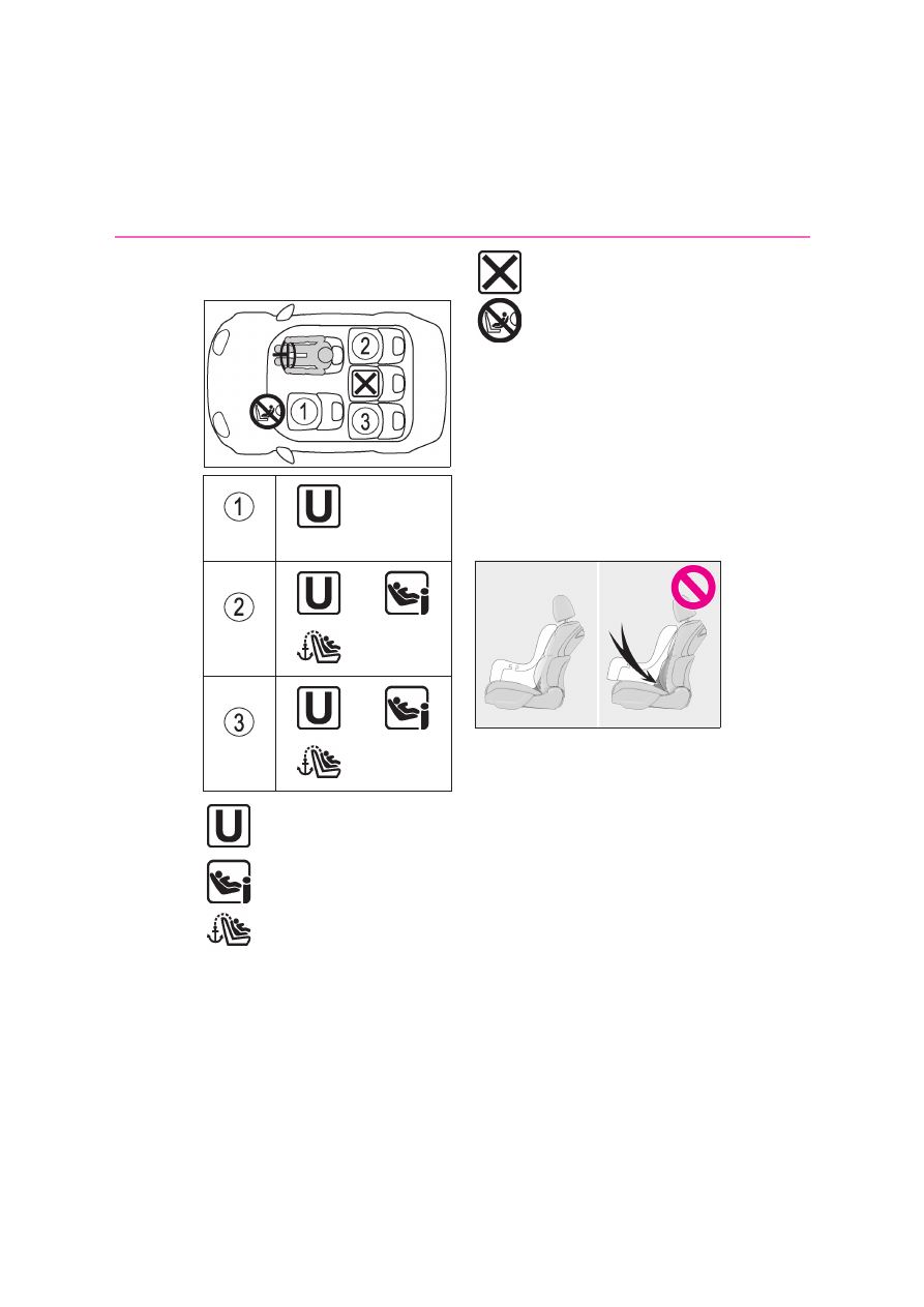
Compatibility of each seating posi-
tion with child restraint systems

*1

: Move the front seat fully rearward. If the 

passenger seat height can be adjusted, 
move it to the upper most position.

*2

: Adjust the seatback angle to the most 

upright position. When installing a for-
ward-facing child seat, if there is a gap 
between the child seat and the 
seatback, adjust the seatback angle 
until good contact is achieved.

*3

: If the head restraint interferes with your 

child restraint system, and the head 
restraint can be removed, remove the 
head restraint.
Otherwise, put the head restraint in the 
upper most position.

*4

: Use only a front-facing child restraint 

system when the airbag manual on-off 
switch is on.

*1, 2, 3

*4

*2, 3

*2, 3

Suitable for “universal” category 
child restraint system fixed with 
the seat belt.
Suitable for i-Size and ISOFIX 
child restraint system.

Includes a top tether anchorage 
point.

Not suitable for child restraint sys-
tem.
Never use a rear-facing child 
restraint system on the front pas-
senger seat when the airbag man-
ual on-off switch is on.
67

1

1-2. Child safety

For safety and security

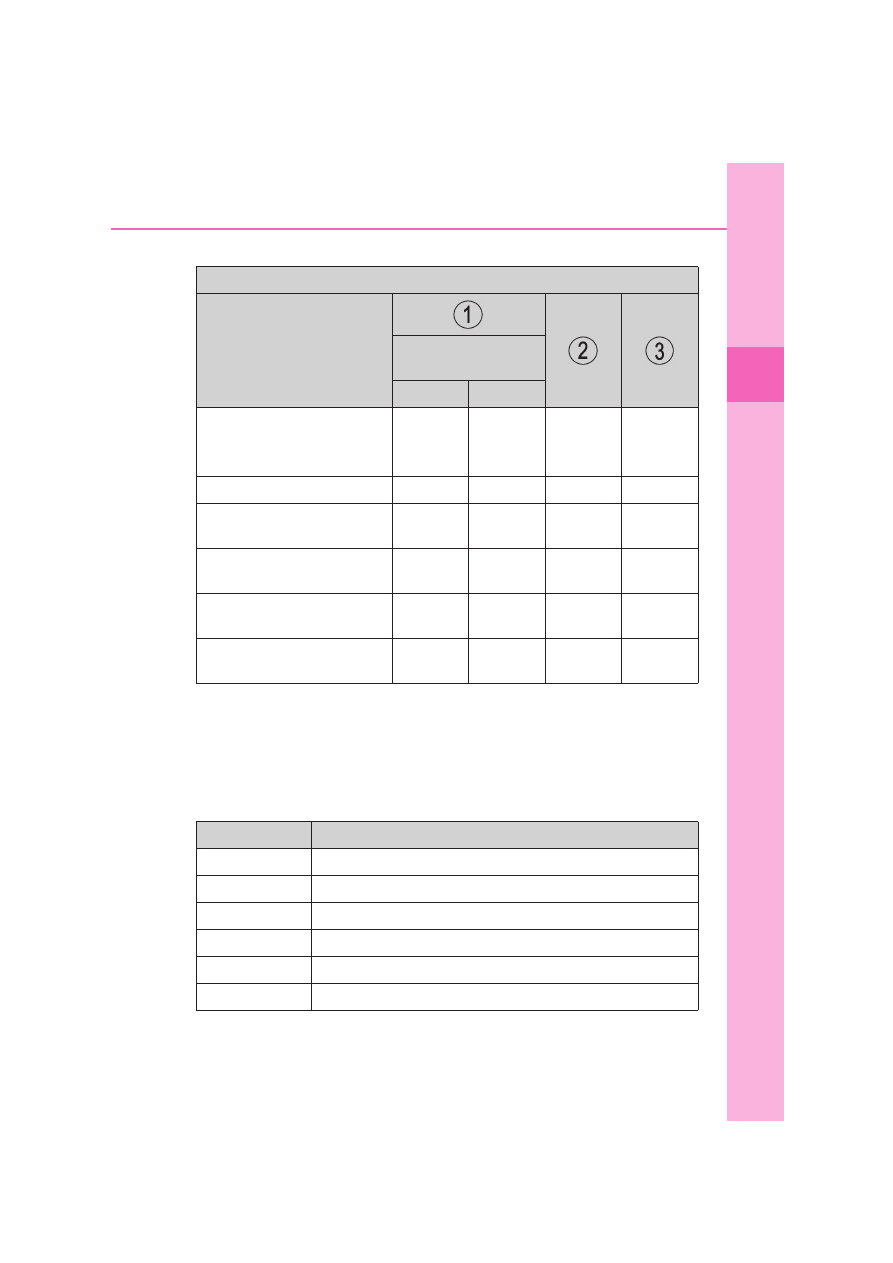
Detail information for CRS installation

ISOFIX child restraint systems are divided into different “fixture”. The child 
restraint system can be used in the seating positions for “fixture” mentioned in the 
table above. For kind of “fixture” relation, confirm the following table.
If your child restraint system has no kind of “fixture” (or if you cannot find informa-
tion in the table below), please refer to the child restraint system “vehicle list” for 
compatibility information or ask the retailer of your child seat.

Seating position

Seat position number

Airbag manual on-off 

switch

ON

OFF

Seating position suitable for uni-

versal belted (yes/no)

yes

Forward 

facing only

yes

yes

yes

i-Size seating position (yes/no)

no

no

yes

yes

Seating position suitable for lateral 

fixture (L1/L2/no)

no

no

no

no

Suitable rearward facing fixture 

(R1/R2X/R2/R3/no)

no

no

R1, R2X, R2, 

R3

R1, R2X, R2, 

R3

Suitable forward facing fixture 

(F2X/F2/F3/no)

no

no

F2X, F2, F3 F2X, F2, F3

Suitable junior seat fixture 

(B2/B3/no)

no

no

B2, B3

B2, B3

Fixture

Description

F3

Full-height, forward-facing child restraint systems

F2

Reduced-height forward-facing child restraint systems

F2X

Reduced-height forward-facing child restraint systems

R3

Full-size, rearward-facing child restraint systems

R2

Reduced-size, rearward-facing child restraint systems

R2X

Reduced-size, rearward-facing child restraint systems

68

1-2. Child safety

When securing some types of child 
restraint systems in rear seat, it may not 
be possible to properly use the seat 
belts in positions next to the child 
restraint without interfering with it or 
affecting seat belt effectiveness. Be 
sure your seat belt fits snugly across 
your shoulder and low on your hips. If it 
does not, or if it interferes with the child 
restraint, move to a different position. 
Failure to do so may result in death or 
serious injury.

When installing a child restraint in 
the rear seats, adjust the front seat 
so that it does not interfere with the 
child or child restraint system.

When installing a child seat with 
support base, if the child seat inter-
feres with the seatback when latch-
ing it into the support base, adjust 
the seatback rearward until there is 

no interference.

If the seat belt shoulder anchor is 
ahead of the child seat belt guide, 
move the seat cushion forward.

When installing a junior seat, if the 
child in your child restraint system is 
in a very upright position, adjust the 
seatback angle to the most comfort-
able position. And if the seat belt 
shoulder anchor is ahead of the 
child seat belt guide, move the seat 
cushion forward.

Confirm with the operation manual enclosed with the child restraint system about 
the installation of the child restraint system.

R1

Rearward-facing infant seat

L1

Left lateral-facing (carrycot) infant seat

L2

Right lateral-facing (carrycot) infant seat

B2

Junior seat

B3

Junior seat

Fixture

Description

Child restraint system installation method

69

1

1-2. Child safety

For safety and security

Installing child restraint system 
using a seat belt

Install the child restraint system in 
accordance to the operation manual 
enclosed with the child restraint sys-
tem.
If the child restraint system on hand is 

not within the “universal” category (or 
the necessary information is not in the 
table), refer to the “Vehicle List” pro-
vided by the child restraint system 
maker for various possible installation 
positions, or check the compatibility 
after asking the retailer of the child 
seat. (

P.59, 64)

1

Adjust the seat

Installation method

Page

Seat belt attachment

P.69

ISOFIX lower anchorage 

attachment

P.71

Top tether anchorage 

attachment

P.73

Child restraint system fixed with 
a seat belt

70

1-2. Child safety

When using the front passenger 
seat

If installing the child restraint system to the 
front passenger seat is unavoidable, refer 
to P.55for the front passenger seat adjust-
ment.

When using the power rear seat (if 
equipped)

If there is a gap between the child seat and 
the seatback, adjust the seatback angle 
until good contact is achieved. (

P.56)

2

Run the seat belt through the child 
restraint system and insert the plate 
into the buckle. Make sure that the 
belt is not twisted. Securely fix the 
seat belt to the child restraint sys-
tem in accordance to the directions 
enclosed with the child restraint 
system.

3

If your child restraint system is not 
equipped with a lock-off (a seat belt 

locking feature), secure the child 
restraint system using a locking clip.

4

After installing the child restraint 
system, rock it back and forth to 
ensure that it is installed securely. 
(

P.71)

Removing a child restraint system 
installed with a seat belt

Press the buckle release button and 
fully retract the seat belt.

When releasing the buckle, the child 
restraint system may spring up due to the 
rebound of the seat cushion. Release the 
buckle while holding down the child 
restraint system.
Since the seat belt automatically reels itself, 
slowly return it to the stowing position.

When installing a child restraint system

You may need a locking clip to install the 

child restraint system. Follow the instruc-

tions provided by the manufacturer of the 

system. If your child restraint system does 

not provide a locking clip, you can purchase 

the following item from any authorized 

Lexus retailer or Lexus authorized repairer, 

or any reliable repairer: Locking clip for 

child restraint system

(Part No. 73119-22010)

71

1

1-2. Child safety

For safety and security

ISOFIX lower anchorages 
(ISOFIX child restraint system)

Lower anchorages are provided for the 
outboard rear seats. (Tags displaying 
the location of the anchorages are 
attached to the seats.)

Installation with ISOFIX lower 
anchorage (ISOFIX child restraint 
system)

Install the child restraint system in 
accordance to the operation manual 
enclosed with the child restraint sys-
tem.
If the child restraint system on hand is 
not within the “universal” category (or 
the necessary information is not in the 
table), refer to the “Vehicle List” pro-
vided by the child restraint system 
maker for various possible installation 
positions, or check the compatibility 
after asking the retailer of the child 
seat. (

P.59, 64)

1

Vehicles with power rear seat: 
Adjust the seat

If there is a gap between the child seat and 

the seatback, adjust the seatback angle 

until good contact is achieved. (

P.56)

WARNING

When installing a child restraint sys-

tem

Observe the following precautions. 

Failure to do so may result in death or 

serious injury.

Do not allow children to play with the 

seat belt. If the seat belt becomes 

twisted around a child’s neck, it may 

lead to choking or other serious inju-

ries that could result in death. If this 

occurs and the buckle cannot be 

unfastened, scissors should be used to 

cut the belt.

Ensure that the belt and plate are 

securely locked and the seat belt is not 

twisted.

Shake the child restraint system left 

and right, and forward and backward 

to ensure that it has been securely 

installed.

After securing a child restraint system, 

never adjust the seat.

When a junior seat is installed, always 

ensure that the shoulder belt is posi-

tioned across the center of the child’s 

shoulder. The belt should be kept away 

from the child’s neck, but not so that it 

could fall off the child’s shoulder.

Follow all installation instructions pro-

vided by the child restraint system 

manufacturer.

Child restraint system fixed with 
an ISOFIX lower anchorage

72

1-2. Child safety

2

Open the cover.

3

Insert the tab   into the slit   of 
the cover.

The cover will be held open.

4

Check the positions of the exclu-
sive fixing bars, and install the child 
restraint system to the seat.

The bars are installed in the clearance 

between the seat cushion and seatback.

5

After installing the child restraint 
system, rock it back and forth to 
ensure that it is installed securely. 
(

P.71)

When using a “LEXUS DUO PLUS” 

(for India)

Adjust it to the most reclined position.

B

A

WARNING

When installing a child restraint sys-

tem

Observe the following precautions. 

Failure to do so may result in death or 

serious injury.

After securing a child restraint system, 

never adjust the seat.

When using the lower anchorages, be 

sure that there are no foreign objects 

around the anchorages and that the 

seat belt is not caught behind the child 

restraint system.

73

1

1-2. Child safety

For safety and security

Top tether anchorages

Top tether anchorages are provided 
for the outboard rear seats.
Use top tether anchorages when fixing 
the top strap.

Top tether anchorages
Top strap

Fixing the top strap to the top 
tether anchorages

Install the child restraint system in 
accordance to the operation manual 
enclosed with the child restraint sys-
tem.
Open the top tether anchorages cover, 
latch the hook onto the top tether 
anchorage and tighten the top strap.

Make sure the top strap is securely latched. 
(

P.71)

Hook
Top strap

WARNING

Follow all installation instructions pro-

vided by the child restraint system 

manufacturer.

Using a top tether anchorage

A
B

WARNING

When installing a child restraint sys-

tem

Observe the following precautions. 

Failure to do so may result in death or 

serious injury.

Firmly attach the top strap and make 

sure that the belt is not twisted.

Do not attach the top strap to anything 

other than the top tether anchorages.

After securing a child restraint system, 

never adjust the seat.

Follow all installation instructions pro-

vided by the child restraint system 

manufacturer.

NOTICE

Top tether anchorages

When not in use, make certain to close 

the lid. If it remains open, the lid may be 

damaged.

A
B

74

1-3. Emergency assistance

1-3.Emergency assistance

*1

: Operates within the eCall coverage. 

The system name differs depending on 
the country.

*2

: If equipped

Microphone/Speaker

“SOS” button

*

Indicator lights

*

: This button is intended for communica-

tion with the eCall system operator.
Other SOS buttons available in other 
systems of a motor vehicle do not relate 
to the device and are not intended for 
communication with the eCall system 

operator.

Automatic Emergency Calls

If any airbag deploys, the system is 
designed to automatically call the 
eCall control center.

*

 The answering 

operator receives the vehicle’s loca-
tion, the time of the incident and the 
vehicle VIN, and attempts to speak 
with the vehicle occupants to assess 
the situation. If the occupants are una-
ble to communicate, the operator 
automatically treats the call as an 
emergency and contacts the nearest 
emergency services provider (112 sys-
tem etc.) to describe the situation and 
request that assistance be sent to the 
location.

*

: In some cases, the call cannot be made. 

(

P.75)

Manual Emergency Calls

In the event of an emergency, press the 
“SOS” button to call the eCall control 
center.

*

 The answering operator will 

determine your vehicle’s location, 
assess the situation, and dispatch the 
necessary assistance required.
Make sure to open the cover before 
pressing the “SOS” button.

eCall

*1, 2

eCall is a telematics service that 
uses Global Navigation Satellite 
System (GNSS) data and embed-
ded cellular technology to enable 
the following emergency calls to be 
made: Automatic emergency calls 
(Automatic Collision Notification) 
and manual emergency calls (by 
pressing the “SOS” button). This 
service is required by European 
Union Regulations.

System components

A
B
C

Emergency Notification Ser-
vices

75

1

1-3. Emergency assistance

For safety and security

If you accidentally press the “SOS” button, 
tell the operator that you are not experi-
encing an emergency.

*

: In some cases, the call cannot be made. 

(

P.75)

When the power switch is turned to 
ON mode, the red indicator light will 
illuminate for 10 seconds. Then, the 
green indicator light will illuminate for 
2 seconds and remain illuminated if the 
system is functioning properly. The 
indicator lights indicate the following:

If the green indicator light illumi-
nates and stays on, the system is 
enabled.

If the green indicator light flashes 
twice per second, an automatic or 
manual Emergency Call is being 
made.

If no indicator lights illuminate, the 
system is not enabled.

If the red indicator light illuminates 
at any time other than immediately 
after the power switch is turned to 
ON mode, the system may be mal-
functioning or the backup battery 
may be depleted.

If the red indicator light blinks for 
approximately 30 seconds during 
an Emergency Call, the call has 
been disconnected or the cellular 
network signal is weak.

Free/Open Source Software Informa-

tion

This product contains Free/Open Source 

Software (FOSS).
The license information and/or the source 

code of such FOSS can be found at the fol-

lowing URL.
http://www.opensourceautomotive.com/

dcm/19MC/

Indicator lights

WARNING

When the Emergency Call may not 

be made

It may not be possible to make Emer-

gency Calls in any of the following situ-

ations. In such cases, report to 

emergency services provider (112 sys-

tem etc.) by other means such as 

nearby public phones.

• Even when the vehicle is in the cellular 

phone service area, it may be difficult 

to connect to the eCall control center 

if the reception is poor or the line is 

busy. In such cases, even though the 

system attempts to connect to the 

eCall control center, you may not be 

able to connect to the eCall control 

center to make Emergency Calls and 

contact emergency services.

• When the vehicle is out of the cellular 

phone service area, the Emergency 

Calls cannot be made.

• When any related equipment (such as 

the “SOS” button panel, indicator 

lights, microphone, speaker, DCM, 

antenna, or any wires connecting the 

equipment) is malfunctioning, dam-

aged or broken, the Emergency Call 

cannot be made.

76

1-3. Emergency assistance

WARNING

• During an Emergency Call, the system 

makes repeated attempts to connect 

to the eCall control center. However, if 

it cannot connect to the eCall control 

center due to poor radio wave recep-

tion, the system may not be able to 

connect to the cellular network and 

the call may finish without connecting. 

The red indicator light will blink for 

approximately 30 seconds to indicate 

this disconnection.

If the 12-volt battery’s voltage 

decreases or there is a disconnection, 

the system may not be able to connect 

to the eCall control center.

When the Emergency Call system is 

replaced with a new one

The Emergency Call system should be 

registered. Contact any authorized 

Lexus retailer or Lexus authorized 

repairer, or any reliable repairer.

For your safety

Please drive safely.

The function of this system is to assist 

you in making the Emergency Call in 

case of accidents such as traffic acci-

dents or sudden medical emergencies, 

and it does not protect the driver or 

passengers in any way. Please drive 

safely and fasten your seatbelts at all 

times for your safety.

In case of an emergency, make lives 

the top priority.

If you smell anything burning or other 

unusual smells, leave the vehicle and 

evacuate to a safe area immediately.

If the airbags deploy when the system 

is operating normally, the system 

makes emergency call. The system 

also makes emergency call when the 

vehicle is struck from the rear or rolls 

over, even if the airbags do not deploy.

For safety, do not make the Emergency 

Call while driving.

Making calls during driving may cause 

mishandling of the steering wheel, 

which may lead to unexpected acci-

dents.

Stop the vehicle and confirm the safety 

of your surroundings before making 

the Emergency Call.

When changing fuses, please use the 

specified fuses. Using other fuses may 

cause ignition or smoke in the circuit 

and lead to a fire.

Using the system while there is smoke 

or an unusual smell may cause a fire. 

Stop using the system immediately and 

consult any authorized Lexus retailer 

or Lexus authorized repairer, or any 

reliable repairer.

NOTICE

To prevent damage

Do not pour any liquids onto the “SOS” 

button panel, etc. and do not impact it.

If the “SOS” button panel, speaker or 

microphone malfunctions during an 

Emergency Call or manual mainte-

nance check

It may not be possible to make Emer-

gency Calls, confirm the system status, or 

communicate with the eCall control 

center operator. If any of the above 

equipment is damaged, please consult 

any authorized Lexus retailer or Lexus 

authorized repairer, or any reliable 

repairer.

77

1

1-3. Emergency assistance

For safety and security

Data processing flow

Server
Storage
Processing
DCM

1

Customer activates service on Lexus Customer portal & accepts terms of ser-
vices according to GDPR.

2

Server activates the service in the DCM and defines which vehicle data to col-
lect.

3

Defined vehicle data is collected by the DCM.

4

Data is shared with the server.

5

Data is stored in the server.

6

Data is processed in the server for fulfilling the service.

7

Processed data is presented to the customer.

For a list of eligible service please visit the Lexus Customer portal.

System overview of added service

A
B
C
D

78

1-3. Emergency assistance

Implementing Regulation

Implementing Regulation Annex1 PART3 User Information

Conformity

1. DESCRIPTION OF THE ECALL IN-VEHICLE SYSTEM

1.1.

Overview of the 112-based eCall in-vehicle system, 
its operation and functionalities

O

1.2.

The 112-based eCall service is a public service of 
general interest and is accessible free of charge.

O

1.3.

The 112-based eCall in-vehicle system is activated by 
default. It is activated automatically by means of 
in-vehicle sensors in the event of a severe accident. It 
will also be triggered automatically when the vehicle 
is equipped with a TPS system which does not func-
tion in the event of a severe accident.

O

1.4.

The 112-based eCall in-vehicle system can also be 
triggered manually, if needed. Instructions for manual 
activation of the system

O

1.5.

In the event of a critical system failure that would dis-
able the 112-based eCall in-vehicle system, the fol-
lowing warning will be given to the occupants of the 
vehicle

O

2. INFORMATION ON DATA PROCESSING

79

1

1-3. Emergency assistance

For safety and security

2.1.

Any processing of personal data through the 
112-based eCall in-vehicle system shall comply with 
the personal data protection rules provided for in 
Directives 95/46/EC and 2002/58/EC, and in 
particular, shall be based on the necessity to protect 
the vital interests of the individuals in accordance 
with Article 7(d) of Directive 95/46/EC.

O

2.2.

Processing of such data is strictly limited to the pur-
pose of handling the emergency eCall to the single 
European emergency number 112.

O

2.3. Types of data and its recipients

2.3.1.

The 112-based eCall in-vehicle system may collect 
and process only the following data: Vehicle Identifi-
cation Number, Vehicle type (passenger vehicle or 
light commercial vehicle), Vehicle propulsion storage 
type (gasoline/diesel/CNG/LPG/electric/hydro-
gen), Vehicle last three locations and direction of 
travel, Log file of the automatic activation of the sys-
tem and its timestamp.

O

2.3.2.

Recipients of data processed by the 112-based eCall 
in-vehicle system are the relevant public safety 
answering points designated by the respective public 
authorities of the country on which territory they are 
located, to first receive and handle eCalls to the sin-
gle European emergency number 112.

O

Implementing Regulation Annex1 PART3 User Information

Conformity

80

1-3. Emergency assistance

2.4. Arrangements for data processing

2.4.1.

The 112-based eCall in-vehicle system is designed in 
such a way as to ensure that the data contained in the 
system memory is not available outside the system 
before an eCall is triggered.

O

2.4.2.

The 112-based eCall in-vehicle system is designed in 
such a way as to ensure that it is not traceable and not 
subject to any constant tracking in its normal opera-
tion status.

O

2.4.3.

The 112-based eCall in-vehicle system is designed in 
such a way as to ensure that data in the system inter-
nal memory is automatically and continuously 
removed.

O

2.4.3.1.

The vehicle location data is constantly overwritten in 
the internal memory of the system so as always to 
keep maximum of the last three up-to-date locations 
of the vehicle necessary for the normal functioning of 
the system.

O

2.4.3.2.

The log of activity data in the 112-based eCall in-vehi-
cle system is kept for no longer than necessary for 
attaining the purpose of handling the emergency 
eCall and in any case not beyond 13 hours from the 
moment an emergency eCall was initiated.

O

Implementing Regulation Annex1 PART3 User Information

Conformity

81

1

1-3. Emergency assistance

For safety and security

2.5. Modalities for exercising data subject’s rights

2.5.1.

The data subject (the vehicle’s owner) has a right of 
access to data and as appropriate to request the rec-
tification, erasure or blocking of data, concerning him 
or her, the processing of which does not comply with 
the provisions of Directive 95/46/EC. Any third par-
ties to whom the data have been disclosed have to be 
notified of such rectification, erasure or blocking car-
ried out in compliance with this Directive, unless it 
proves impossible or involves a disproportionate 
effort.

O

2.5.2.

The data subject has a right to complain to the com-
petent data protection authority if he or she consid-
ers that his or her rights have been infringed as a 
result of the processing of his or her personal data.

O

2.5.3.

Contact service responsible for handling access 
requests (if any):

P.82

O

3. INFORMATION ON THIRD PARTY SERVICES AND OTHER ADDED VALUE 
SERVICES (IF FITTED)

Implementing Regulation Annex1 PART3 User Information

Conformity

82

1-3. Emergency assistance

Service responsible for handling access requests

3.1.

Description of the operation and the functionalities of 
the TPS system/added value service

P.77

3.2.

Any processing of personal data through the TPS 
system/other added value service shall comply with 
the personal data protection rules provided for in 
Directives 95/46/EC and 2002/58/EC.

O

3.2.1.

Legal basis for the use of TPS system and/or added 
value services and for processing data through them

The Euro-

pean Union 

General Data 

Protection 

Regulation

3.3.

The TPS system and/or other added value services 
shall process personal data only on the base of the 
explicit consent of the data subject (the vehicle’s 
owner or owners).

O

3.4.

Modalities for data processing through TPS system 
and/or other added value services, including any 
necessary additional information regarding tracea-
bility, tracking and processing of personal data

P.77

3.5.

The owner of a vehicle equipped with a TPS eCall 
system and/or other added value service in addition 
to the 112-based eCall in-vehicle system has the right 
to choose to use the 112-based eCall in-vehicle sys-
tem rather than the TPS eCall system and the other 
added value service.

O

3.5.1.

Contact details for handling TPS eCall system deac-
tivation requests

N/A

Country

Contact information

Austria

datenschutz@toyota-frey.at

Belgium/Luxembourg

privacy@toyota.be

Croatia

dpcp@toyota.hr

Czech Republic/
Hungary/Slovakia

adatvedelem@toyota-ce.com

Implementing Regulation Annex1 PART3 User Information

Conformity

83

1

1-3. Emergency assistance

For safety and security

Denmark

toyota@toyota.dk og

Estonia

privacy@toyota.ee

Finland

tietosuoja@toyota.fi

France

delegue.protectiondonnees@toyota-europe.com

Germany

Toyota.Datenschutz@toyota.de

Great Britain

privacy@tgb.toyota.co.uk

Greece

customer@toyota.gr

Iceland

personuvernd@toyota.is

Ireland

customerservice@toyota.ie

Italy

tmi.dpo@toyota-europe.com

Netherlands

www.toyota.nl/klantenservice

Norway

personvern@toyota.no

Poland

klient@toyota.pl

Portugal

gestaodadospessoais@toyotacaetano.pt

Romania

relatii.clienti@toyota.ro

Slovenia

dpcp@toyota.si

Spain

clientes@toyota.es / dpo@toyota.es.

Sweden

integritet@toyota.se

Switzerland

info@toyota.ch

Country

Contact information

84

1-4. Hybrid system

1-4.Hybrid system

System components

The illustration is an example for explanation and may differ from the actual item.

Gasoline engine
Electric motor (traction motor)

When stopped/during start off

The gasoline engine stops

*

 when the 

vehicle is stopped. During start off, the 
electric motor (traction motor) drives 
the vehicle. At slow speeds or when 
traveling down a gentle slope, the 
engine is stopped

*

 and the electric 

motor (traction motor) is used.

When the shift position is in N, the 
hybrid battery (traction battery) is not 
being charged.

*

: When the hybrid battery (traction bat-

tery) requires charging or the engine is 
warming up, etc., the gasoline engine will 
not automatically stop.

During normal driving

The gasoline engine is predominantly 

Hybrid system features

Your vehicle is a hybrid electric vehicle. It has characteristics different from 
conventional vehicles. Be sure you are closely familiar with the characteristics 
of your vehicle, and operate it with care.

The hybrid system combines the use of a gasoline engine and an electric motor 
(traction motor) according to driving conditions, improving fuel efficiency and 
reducing exhaust emissions.

System components

A
B

85

1

1-4. Hybrid system

For safety and security

used. The electric motor (traction 
motor) charges the hybrid battery 
(traction battery) as necessary.

When accelerating sharply

When the accelerator pedal is 
depressed heavily, the power of the 
hybrid battery (traction battery) is 
added to that of the gasoline engine via 
the electric motor (traction motor).

When braking (regenerative brak-
ing)

The wheels operate the electric motor 
(traction motor) as a power generator, 
and the hybrid battery (traction bat-
tery) is charged.

Regenerative braking

In the following situations, kinetic energy 

is converted to electric energy and 

deceleration force can be obtained in 

conjunction with the recharging of the 

hybrid battery (traction battery).

• The accelerator pedal is released while 

driving with the shift position in D or M.

• The brake pedal is depressed while driv-

ing with the shift position in D or M.

Vehicles with GPF system: While the 

GPF system (

P.376) is operating to 

regenerate the exhaust gas filter, the 

hybrid battery (traction battery) may not 

be recharged.

EV indicator

The EV indicator comes on when the vehi-

cle is driven using only the electric motor 

(traction motor) or the gasoline engine is 

stopped.

Conditions in which the gasoline engine 

may not stop

The gasoline engine starts and stops auto-

matically. However, it may not stop auto-

matically in the following conditions:

During gasoline engine warm-up

During hybrid battery (traction battery) 

charging

When the temperature of the hybrid bat-

tery (traction battery) is high or low

When the heater is switched on

When the shift position is in M

Depending on the circumstances, the gaso-

line engine may also not stop automatically 

in other situations.

Charging the hybrid battery (traction 

battery)

As the gasoline engine charges the hybrid 

battery (traction battery), the battery does 

not need to be charged from an outside 

source. However, if the vehicle is left parked 

for a long time the hybrid battery (traction 

battery) will slowly discharge. For this rea-

son, be sure to drive the vehicle at least 

once every few months for at least 30 min-

utes or 16 km (10 miles). If the hybrid bat-

tery (traction battery) becomes fully 

discharged and you are unable to start the 

hybrid system, contact any authorized 

Lexus retailer or Lexus authorized repairer, 

or any reliable repairer.

Charging the 12-volt battery

P.514

After the 12-volt battery has discharged 

or when the terminal has been removed 

and installed during exchange, etc.

The gasoline engine may not stop even if 

the vehicle is being driven by the hybrid bat-

86

1-4. Hybrid system

tery (traction battery). If this continues for a 

few days, contact any authorized Lexus 

retailer or Lexus authorized repairer, or any 

reliable repairer.

Sounds and vibrations specific to a 

hybrid electric vehicle

Because there is no engine sound or vibra-

tion, it is easy to mistake the hybrid electric 

vehicle for being off when it is actually still 

running, as indicated by the “READY” indi-

cator being illuminated. For safety, make 

sure to always shift the shift position to P 

and apply the parking brake when parked.
The following sounds or vibrations may 

occur when the hybrid system is operating 

and are not a malfunction:

Motor sounds may be heard from the 

engine compartment.

Relay operating sounds such as a snap or 

soft clank will be emitted from the hybrid 

battery (traction battery), behind the rear 

seats, when the hybrid system is started 

or stopped.

Sounds may be heard from the hybrid 

battery (traction battery) behind the rear 

seats when the hybrid system starts or 

stops.

Sounds from the hybrid system may be 

heard when the trunk lid is open.

Sounds may be heard from the transmis-

sion when the gasoline engine starts or 

stops, when driving at low speeds, or dur-

ing idling.

Engine sounds may be heard when 

accelerating sharply.

Sounds may be heard due to regenera-

tive braking when the brake pedal is 

depressed or as the accelerator pedal is 

released.

Vibration may be felt or sounds may be 

heard when the gasoline engine starts or 

stops.

Cooling fan sounds may be heard from 

the air intake vents on the both sides of 

the rear seatback.

Maintenance, repair, recycling, and dis-

posal

Contact any authorized Lexus retailer or 

Lexus authorized repairer, or any reliable 

repairer regarding maintenance, repair, 

recycling and disposal. Do not dispose of 

the vehicle yourself.

Customization

Some functions can be customized. 

(

P.540)

When driving with the gasoline engine 
stopped, a sound, which changes in 
accordance with the driving speed, will 
be played in order to warn people 
nearby of the vehicle’s approach. The 
sound will stop when the vehicle speed 
exceeds approximately 25km/h (15 
mph).

Acoustic Vehicle Alerting System

In the following cases, the Acoustic Vehicle 

Alerting System may be difficult for sur-

rounding people to hear.

In very noisy areas

In the wind or the rain

Also, as the Acoustic Vehicle Alerting Sys-

tem is installed on the front of the vehicle, it 

may be more difficult to hear from the rear 

of the vehicle compared to the front.

Acoustic Vehicle Alerting Sys-
tem

87

1

1-4. Hybrid system

For safety and security

The illustration is an example for explanation and may differ from the actual item.

Except for Turkey: Warning label
For Turkey: Warning label
Power control unit
Electric motor (traction motor)
Hybrid battery (traction battery)
Service plug
High voltage cables (orange)
Air conditioning compressor

Running out of fuel

When the vehicle has run out of fuel and the 

hybrid system cannot be started, refuel the 

vehicle with at least enough gasoline to 

make the low fuel level warning light 

(

P.499) go off. If there is only a small 

amount of fuel, the hybrid system may not 

be able to start. (The standard amount of 

fuel is about 13 L [3.4 gal., 2.8 Imp. gal.], 

when the vehicle is on a level surface. This 

value may vary when the vehicle is on a 

slope. Add extra fuel when the vehicle is 

inclined.)

Hybrid system precautions

Take care when handling the hybrid system, as it is a high voltage system (about 
650 V at maximum) as well as contains parts that become extremely hot when 
the hybrid system is operating. Obey the warning labels attached to the vehi-
cle.

System components

A
B
C
D

E
F

G

H

88

1-4. Hybrid system

Electromagnetic waves

High voltage parts and cables on hybrid 

electric vehicles incorporate electro-

magnetic shielding, and therefore emit 

approximately the same amount of elec-

tromagnetic waves as conventional gaso-

line powered vehicles or home electronic 

appliances.

Your vehicle may cause sound interfer-

ence in some third party-produced radio 

parts.

Hybrid battery (traction battery)

The hybrid battery (traction battery) has a 

limited service life. The lifespan of the 

hybrid battery (traction battery) can 

change in accordance with driving style and 

driving conditions.

Starting the hybrid system in an 

extremely cold environment

When the hybrid battery (traction battery) 

is extremely cold (below approximately 

-30°C [-22°F]) under the influence of the 

outside temperature, it may not be possible 

to start the hybrid system. In this case, try to 

start the hybrid system again after the tem-

perature of the hybrid battery increases due 

to the outside temperature increase etc.

Declaration of conformity

This model conforms to hydrogen emis-

sions according to regulation ECE100 

(Battery electric vehicle safety).

WARNING

High voltage precautions

This vehicle has high voltage DC and AC 

systems as well as a 12-volt system. DC 

and AC high voltage is very dangerous 

and can cause severe burns and electric 

shock that may result in death or serious 

injury.

Never touch, disassemble, remove or 

replace the high voltage parts, cables 

or their connectors.

The hybrid system will become hot 

after starting as the system uses high 

voltage. Be careful of both the high 

voltage and the high temperature, and 

always obey the warning labels 

attached to the vehicle.

Never try to open the service plug 

access hole located behind the rear 

seat. The service plug is used only 

when the vehicle is serviced and is 

subject to high voltage.

Road accident cautions

Observe the following precautions to 

reduce the risk of death or serious injury:

Stop the vehicle in a safe place to pre-

vent subsequent accidents. While 

depressing the brake pedal, apply the 

parking brake and shift the shift posi-

tion to P to stop the hybrid system. 

Then, slowly release the brake pedal.

Do not touch the high voltage parts, 

cables and connectors.

If electric wires are exposed inside or 

outside your vehicle, an electric shock 

may occur. Never touch exposed elec-

tric wires.

89

1

1-4. Hybrid system

For safety and security

WARNING

Do not touch the battery if liquid is 

leaking from or adhering to it.

If electrolyte (carbonate ester-based 

organic electrolyte) from the hybrid 

battery (traction battery) comes into 

contact with the eyes or skin, it could 

cause blindness or skin wounds. In the 

unlikely event that it comes into con-

tact with the eyes or skin, wash it off 

immediately with a large amount of 

water, and seek immediate medical 

attention.

If electrolyte is leaking from the hybrid 

battery (traction battery), do not 

approach the vehicle.

Even in the unlikely event that the 

hybrid battery (traction battery) is 

damaged, the internal construction of 

the battery will prevent a large amount 

of electrolyte from leaking out. How-

ever, any electrolyte that does leak out 

will give off a vapor. This vapor is an 

irritant to skin and eyes and could 

cause acute poisoning if inhaled.

Do not bring burning or high-temper-

ature items close to the electrolyte. 

The electrolyte may ignite and cause a 

fire.

If a fire occurs in the hybrid electric 

vehicle, leave the vehicle as soon as 

possible. Never use a fire extinguisher 

that is not meant for electric fires. 

Using even a small amount of water 

may be dangerous.

If your vehicle needs to be towed, do 

so with four wheels raised. If the 

wheels connected to the electric 

motor (traction motor) are on the 

ground when towing, the motor may 

continue to generate electricity. This 

may cause a fire. (

P.489)

Carefully inspect the ground under the 

vehicle. If you find that liquid has 

leaked onto the ground, the fuel sys-

tem may have been damaged. Leave 

the vehicle as soon as possible.

Hybrid battery (traction battery)

Your vehicle contains a sealed lith-

ium-ion battery.

Never resell, hand over or modify the 

hybrid battery. To prevent accidents, 

hybrid batteries that have been 

removed from a disposed vehicle are 

collected through any authorized 

Lexus retailer or Lexus authorized 

repairer, or any reliable repairer. Do 

not dispose of the battery yourself.

Unless the battery is properly collected, 
the following may occur, resulting in 
death or serious injury:
• The hybrid battery may be illegally dis-

posed of or dumped, and it is hazard-

ous to the environment or someone 

may touch a high voltage part, result-

ing in an electric shock.

• The hybrid battery is intended to be 

used exclusively with your hybrid elec-

tric vehicle. If the hybrid battery is used 

outside of your vehicle or modified in 

any way, accidents such as electric 

shock, heat generation, smoke gener-

ation, an explosion and electrolyte 

leakage may occur.

When reselling or handing over your 
vehicle, the possibility of an accident is 
extremely high because the person 
receiving the vehicle may not be aware 
of these dangers.

If your vehicle is disposed of without 

the hybrid battery having been 

removed, there is a danger of serious 

electric shock if high voltage parts, 

cables and their connectors are 

touched. In the event that your vehicle 

must be disposed of, the hybrid battery 

must be disposed of by any authorized 

Lexus retailer or Lexus authorized 

repairer, or any reliable repairer. If the 

hybrid battery is not disposed of prop-

erly, it may cause electric shock that 

can result in death or serious injury.

90

1-4. Hybrid system

There are air intake vents on each side 
of the rear seatback with the purpose 
of cooling the hybrid battery (traction 
battery).
If the vents are blocked, it may interfere 
with the cooling of the hybrid battery 
(traction battery).

If input/output of the hybrid battery (trac-
tion battery) becomes limited and the dis-
tance that the vehicle can be driven using 
the electric motor (traction motor) is 
reduced, the fuel economy may be 
reduced.

When a certain level of impact is 
detected by the impact sensor, the 
emergency shut off system blocks the 
high voltage current and stops the fuel 
pump to minimize the risk of electrocu-
tion and fuel leakage. If the emergency 
shut off system activates, your vehicle 
will not restart. To restart the hybrid 
system, contact any authorized Lexus 
retailer or Lexus authorized repairer, 
or any reliable repairer.

A message is automatically displayed 
when a malfunction occurs in the 
hybrid system or an improper opera-
tion is attempted.
If a warning message is shown on the 
multi-information display, read the 

NOTICE

Hybrid battery (traction battery)

Do not carry large amounts of water 

such as water cooler bottles in the vehi-

cle. If water spills onto the hybrid battery 

(traction battery), the battery may be 

damaged. Have the vehicle inspected by 

any authorized Lexus retailer or Lexus 

authorized repairer, or any reliable 

repairer.

Hybrid battery (traction bat-
tery) air intake vents

NOTICE

Hybrid battery (traction battery) air 

intake vents

Make sure not to block the air intake 

vent with anything, such as a seat 

cover, plastic cover, or luggage.

The input/output of the hybrid battery 

(traction battery) may be restricted, 

leading to a reduction in hybrid battery 

(traction battery) output and a mal-

function.

Periodically clean the air intake vents 

to prevent them from clogging. 

(

P.475)

Do not get water or foreign materials 

in the air intake vents as this may cause 

a short circuit and damage the hybrid 

battery (traction battery).

Emergency shut off system

Hybrid warning message

91

1

1-4. Hybrid system

For safety and security

message and follow the instructions.

If a warning light comes on, a warning 

message is displayed, or the 12-volt bat-

tery is disconnected

The hybrid system may not start. In this 

case, try to start the system again. If the 

“READY” indicator does not come on, con-

tact any authorized Lexus retailer or Lexus 

authorized repairer, or any reliable repairer.

92

1-5. Theft deterrent system

1-5.Theft deterrent system

The indicator light flashes after the 
power switch has been turned off to 
indicate that the system is operating.
The indicator light stops flashing after 
the power switch has been turned to 
ACCESSORY or ON mode to indi-
cate that the system has been 
canceled.

System maintenance

The vehicle has a maintenance-free type 

immobilizer system.

Conditions that may cause the system to 

malfunction

If the grip portion of the key is in contact 

with a metallic object

If the key is in close proximity to or touch-

ing a key to the security system (key with 

a built-in transponder chip) of another 

vehicle

Immobilizer system

The vehicle’s keys have built-in 
transponder chips that prevent the 
hybrid system from starting if a key 
has not been previously registered 
in the vehicle’s on-board computer.

Never leave the keys inside the 
vehicle when you leave the vehicle.

This system is designed to help pre-
vent vehicle theft but does not 
guarantee absolute security 
against all vehicle thefts.

Operating the system

NOTICE

To ensure the system operates cor-

rectly

Do not modify or remove the system. If 

modified or removed, the proper opera-

tion of the system cannot be guaranteed.

93

1

1-5. Theft deterrent system

For safety and security

Setting

Turn the power switch off, have all the 
passengers exit the vehicle and ensure 
that all the doors are closed.
Using the entry function: Touch the 
sensor area on the outside door handle 
twice within 5 seconds.
Using the wireless remote control: 
Press 

 twice within 5 seconds.

Canceling

Using the entry function: Hold the out-
side door handle, press the power 
trunk lid switch or move your foot 
under the center of the rear bumper 
(vehicles with a Hands Free Power 

Trunk Lid).
Using the wireless remote control: 
Press .

Double locking system

Unauthorized access to the vehicle 
is prevented by disabling the door 
unlocking function from both the 
interior and exterior of the vehicle.

Vehicles employing this system 
have labels on the window glass of 
both front doors.

Setting/canceling the double 
locking system

WARNING

Double locking system precaution

Never activate the double locking sys-

tem when there are people in the vehicle 

because all the doors cannot be opened 

from inside the vehicle.

94

1-5. Theft deterrent system

*

: If  equipped

Items to check before locking the 
vehicle

To prevent unexpected triggering of 
the alarm and vehicle theft, make sure 
of the following:

Nobody is in the vehicle.

The windows and moon roof are 
closed before the alarm is set.

No valuables or other personal 
items are left in the vehicle.

Setting

Close the doors, trunk and hood, and 
lock all the doors using the entry func-
tion or wireless remote control. The 
system will be set automatically after 
30 seconds.

The indicator light changes from being on 
to flashing when the system is set.

Deactivating or stopping

Do one of the following to deactivate 
or stop the alarms:

Unlock the doors or open the trunk 
using the entry function or wireless 
remote control.

Starting the hybrid system. (The 
alarm will be deactivated or stopped 
after a few seconds.)

System maintenance

The vehicle has a maintenance-free type 

alarm system.

Triggering of the alarm

The alarm may be triggered in the following 

situations: 

(Stopping the alarm deactivates the alarm 

system.)

The doors are unlocked using the 

mechanical key.

Alarm

*

The alarm uses light and sound to 
give an alert when an intrusion is 
detected. 
The alarm is triggered in the follow-
ing situations when the alarm is set:

A locked door or trunk is 
unlocked or opened in any way 
other than using the entry func-
tion or wireless remote control. 
(The doors will lock again auto-
matically.)

The hood is opened.

The intrusion sensor detects 
something moving inside the 
vehicle. (Example: an intruder 
breaks a window and gets into the 
vehicle.)

The tilt sensor detects a change of 
vehicle inclination.

Setting/deactivating/stopping 
the alarm system

95

1

1-5. Theft deterrent system

For safety and security

The trunk is opened using the mechanical 

key.

A person inside the vehicle opens a door, 

the trunk or hood, or unlocks the vehicle.

The 12-volt battery is recharged or 

replaced when the vehicle is locked. 

(

P.519)

Alarm-operated door lock

In the following cases, depending on the sit-

uation, the door may automatically lock to 

prevent improper entry into the vehicle:

When a person remaining in the vehicle 

unlocks the door and the alarm is acti-

vated.

While the alarm is activated, a person 

remaining in the vehicle unlocks the door.

The intrusion sensor and tilt sensor 
detection

The intrusion sensor detects intrud-
ers or movement in the vehicle.

The tilt sensor detects changes in 
vehicle inclination, such as when the 
vehicle is towed away.

This system is designed to deter and 
prevent vehicle theft but does not 
guarantee absolute security against all 
intrusions.

Setting the intrusion sensor and tilt 
sensor

The intrusion sensor and tilt sensor will 
be set automatically when the alarm is 
set. (

P.94)

Canceling the intrusion sensor and 
tilt sensor

If you are leaving pets or other moving 
things inside the vehicle, make sure to 
disable the intrusion sensor and tilt 
sensor before setting the alarm, as they 
will respond to movement inside the 
vehicle.

NOTICE

To ensure the system operates cor-

rectly

Do not modify or remove the system. If 

modified or removed, the proper opera-

tion of the system cannot be guaranteed.

The intrusion sensor and tilt sen-
sor detection

96

1-5. Theft deterrent system

1

Turn the power switch off.

2

Press the intrusion sensor and tilt 
sensor cancel switch.

Press the switch again to re-enable the 

intrusion sensor and tilt sensor.
Each time the intrusion sensor and tilt sen-

sor are canceled/set, a message will be 

shown on the multi-information display.

Canceling and automatic re-enabling of 

the intrusion sensor and tilt sensor

The alarm will still be set even when the 

intrusion sensor and tilt sensor are 

canceled.

After the intrusion sensor and tilt sensor 

are canceled, pressing the power switch 

or unlocking the doors using the entry 

function or wireless remote control will 

re-enable the intrusion sensor and tilt 

sensor.

The intrusion sensor and tilt sensor will 

automatically be re-enabled when the 

alarm system is deactivated.

Intrusion sensor detection considera-

tions

The sensor may trigger the alarm in the fol-

lowing situations:

People or pets are in the vehicle.

A window or moon roof is open.

In this case, the sensor may detect the fol-
lowing:
• Wind or the movement of objects such as 

leaves and insects inside the vehicle

• Ultrasonic waves emitted from devices 

such as the intrusion sensors of other 

vehicles

• The movement of people outside the 

vehicle

Small insects such as moths or flies are in 

the vehicle.

Unstable items, such as dangling acces-

sories or clothes hanging on the coat 

hooks, are in the vehicle.

The vehicle is parked in a place where 

extreme vibrations or noises occur, such 

as in a parking garage.

97

1

1-5. Theft deterrent system

For safety and security

Ice or snow is removed from the vehicle, 

causing the vehicle to receive repeated 

impacts or vibrations.

The vehicle is inside an automatic or 

high-pressure car wash.

The vehicle experiences impacts, such as 

hail, lightning strikes, and other kinds of 

repeated impacts or vibrations.

Tilt sensor detection considerations

The sensor may trigger the alarm in the fol-

lowing situations:

The vehicle is transported by a ferry, 

trailer, train, etc.

The vehicle is parked in a parking garage.

The vehicle is inside a car wash that 

moves the vehicle.

Any of the tires loses air pressure.

The vehicle is jacked up.

An earthquake occurs or the road caves 

in.

Cargo is loaded onto or unloaded from 

the roof luggage carrier.

NOTICE

To ensure the intrusion sensor func-

tion correctly

To ensure that the sensors operate 

properly, do not touch or cover them.

Do not spray air fresheners or other 

products directly into the sensor holes.

Installing accessories other than genu-

ine Lexus parts or leaving objects 

between the driver’s seat and front 

passenger’s seat may reduce the 

detection performance.


Content      ..      1      2      3      ..