Harley Davidson 1999-2005 Harley Dyna Models. Repair Manual - page 23
-------------------------------------------------------------------------------------------------------------------------------------------------------------
440
CHAPTER ELEVEN
Compression Rebound Adjustment
(FXDX, FXDXT)
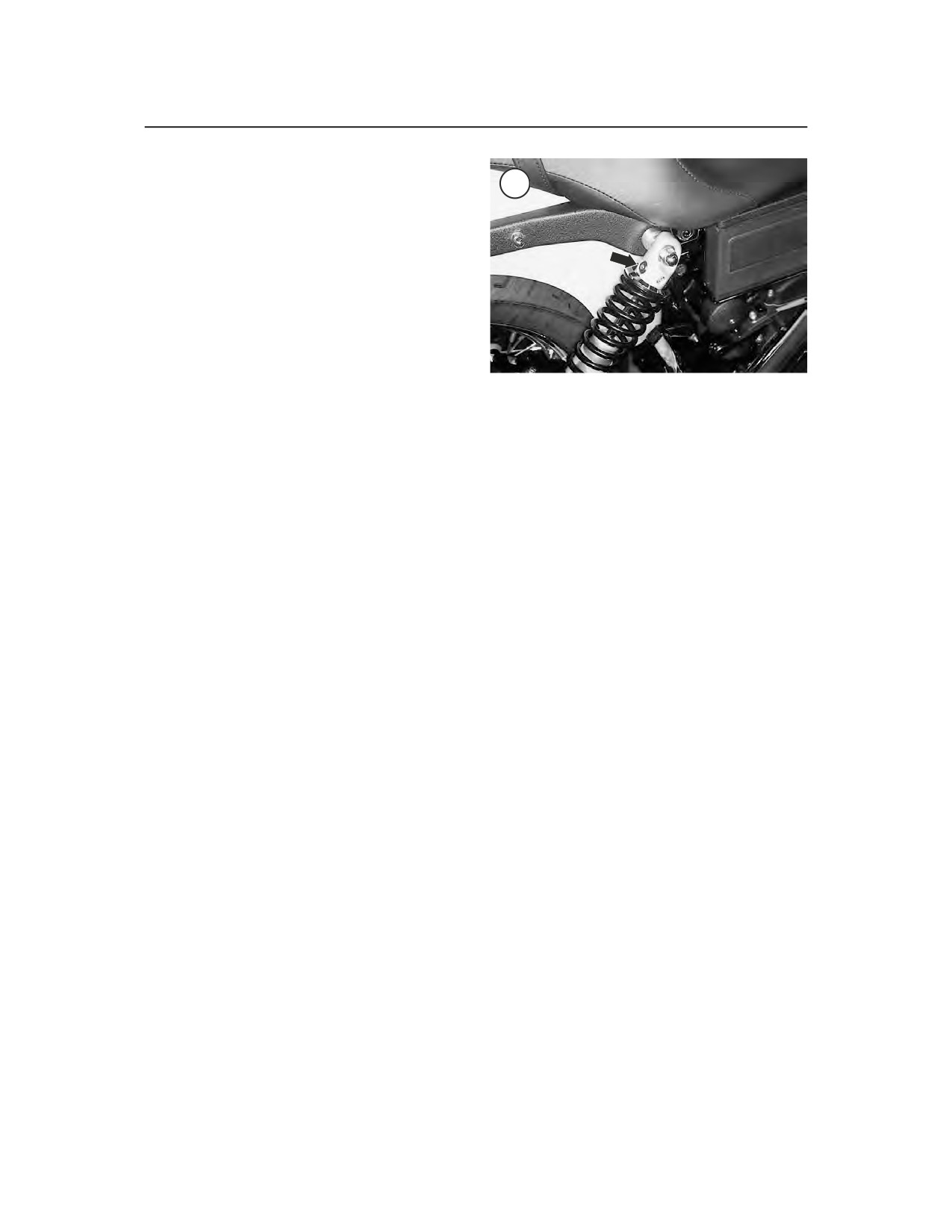
15
The compression rebound adjuster (Figure 15)
has ten stop positions. The No. 1 position which is
all the way clockwise, is the hardest, while the No.
10 position, all the way counterclockwise, is the
softest. The standard factory setting is No. 3.
To adjust the compression damping, turn the
compression damping adjuster with a small blade
screwdriver located at the top of the shock absorber.
NOTE
When turning the adjuster, make sure
2. Remove the bolts and nuts securing the drive
it clicks into one of the detent posi-
belt upper guard (A, Figure 19) and remove the
tions. Otherwise, the adjuster will au-
guard.
tomatically be set at the stiffest
3. Remove the rear wheel (B, Figure 19) as de-
position.
scribed in Chapter Nine.
4. On 1999 models, slide the rear brake caliper off
REAR SWING ARM
the swing arm as described in Chapter Twelve.
5. Remove the mounting bolts securing the left side
Refer to Figure 16 and Figure 17.
rear footpeg and mounting bracket assembly (A,
Figure 20). Remove the assembly.
Rear Swing Arm Bearing Check
6. Remove the acorn nut and washer (A, Figure
21) securing each shock absorber to the swing arm.
The swing arm pivots on a combination bushing
Pivot both shock absorbers up and tie it to the frame.
and bearing assembly. Service limit specifications
7. On the right side, remove the bolts securing the
for the bushing and bearing assemblies are not
muffler support bracket (A, Figure 22) to the frame
available; therefore, check for wear or damage with
and remove it.
the swing arm mounted on the frame.
8. Remove the clamps securing the rear brake hose
1. Remove the rear wheel (A, Figure 18) as de-
to the swing arm.
scribed in this chapter.
9. On the right side, pry the pivot shaft chrome cap
2. Remove the lower acorn nut and washer (B, Fig-
(B, Figure 22) from the swing arm.
ure 18) securing both shock absorbers to the swing
10A. On 1999 models, perform the following:
arm. Move them up away from the swing arm.
3. Check that the swing arm pivot shaft nut or bolt
a. On the left side, remove the cotter pin from
is tight.
the end of the pivot shaft (Figure 23). Install a
4. Have an assistant hold the motorcycle securely.
new cotter pin during installation.
5. Grasp the back of the swing arm and try to move
b. Hold the nut and loosen the pivot shaft (Fig-
it from side to side. Any play (movement) between
ure 24) on the right side. Remove the nut and
the swing arm and the frame and transmission may
washer.
suggest worn or damaged swing arm bearings
c. Support the swing arm and remove the pivot
and/or bushings. If there is any play, remove the
shaft (Figure 24) from the right side.
swing arm and inspect the bushing and bearing as-
d. Remove the swing arm (Figure 25).
semblies.
10B. On 2000-on models, perform the following:
6. Install all components removed.
a. On the right side, hold onto the hex fitting on
the end of the pivot shaft to keep the shaft
from rotating.
Rear Swing Arm Removal
b. On the left side, remove the bolt and
1. Remove the exhaust system as described in
lockwasher (B, Figure 20) from the pivot
Chapter Seven.
shaft.