Harley Davidson 2008 Touring Models. Electrical Diagnostics Manual - page 39
HOME
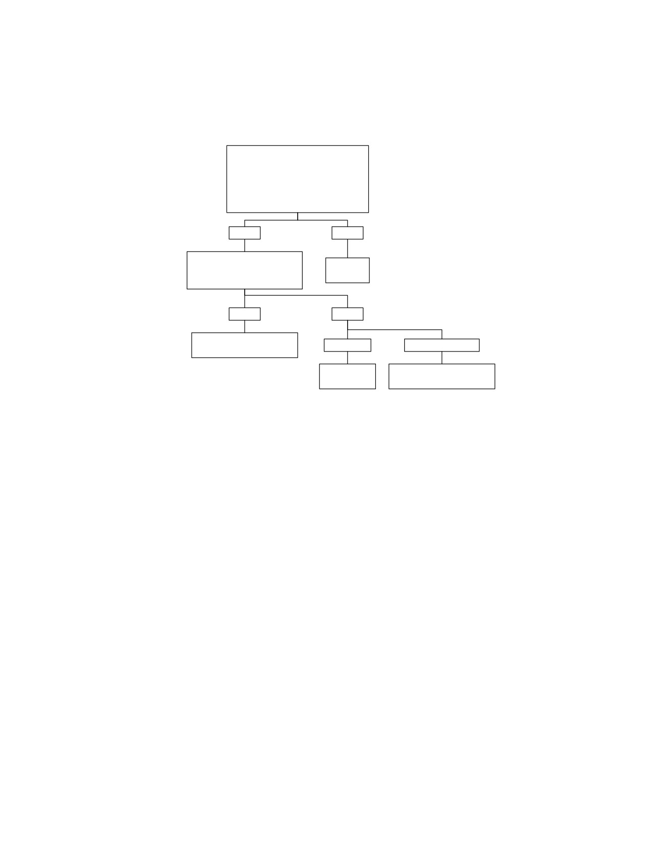
Turn Signal Error 2C Will Not Flash, 4-way Flashers Inoperable: DTC: B1121, B1122, B1141
Continued from Turn Signal Error 2A Will
Not Flash, 4-way Flashers Inoperable:
DTC B1121, B1122, B1141.
Check resistance to Ground on
Breakout Box terminal “12” (Gray).
Is resistance less than 1 ohm?
YES
NO
Check for 12 volts at both
terminals of 15 amp Battery Fuse.
Repair poor
Proper voltage present at both
Ground.
terminals?
6805
YES
NO
Repair open in (BN/GY) wire
1 terminal.
Neither terminal.
between Battery Fuse and TSM.
6806
Replace Battery
Repair open between 40 Amp
Fuse.
MAXIFUSE and Fuse Block.
6807
6808
fc01324_en
2008 Touring Diagnostics: Appendix E TSM/TSSM (Japan/Korea) E-41
HOME
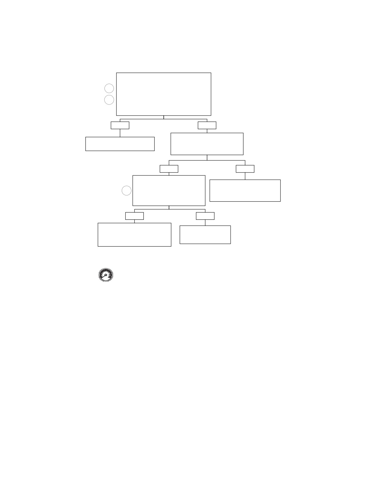
Turn Signal Error 2D Will Not Flash, 4-way Flashers Inoperable: DTC: B1121, B1122, B1141
Continued from Turn Signal Error 2A Will Not
Flash, 4-way Flashers Inoperable: DTC B1121,
3
B1122, B1141.
Check for battery voltage at Breakout Box terminal
5
“7” (Gray) with right turn signal depressed and
terminal “8” (Gray) with left turn signal depressed.
Is battery voltage present?
YES
NO
Check for battery voltage on terminal
Replace TSSM.
“1” connector [22B] (right), or terminal
Learn password and perform set-up.
“1” connector [24B] (left).
Battery voltage present?
6791
YES
NO
With turn signal switch depressed
on side being tested, check for
Locate and repair open (O/W) wire
continuity between terminal “1” and
between terminal “1” on connector
4
terminal “5” on connector [22A]
[22B] (right), or terminal “1” connector
(right), or connector [24A] (left).
[24B] (left) and accessory fuse.
Continuity present?
6814 - right
6812 - left
YES
NO
Locate and repair open wire
Replace turn signal
between terminal “5” on connector
switch or repair wiring to
[22B] (right), or terminal “5” connector
turn signal switch?
[24B] (left) and TSM connector [30].
6811
6813 - right
6810 - left
fc01325_en
Clear DTCs using speedometer self diagnostics.
See E. 10 SPEEDOMETER SELF DIAGNOSTICS.
Confirm proper operation with no check engine
lamp.
E-42 2008 Touring Diagnostics: Appendix E TSM/TSSM (Japan/Korea)
HOME
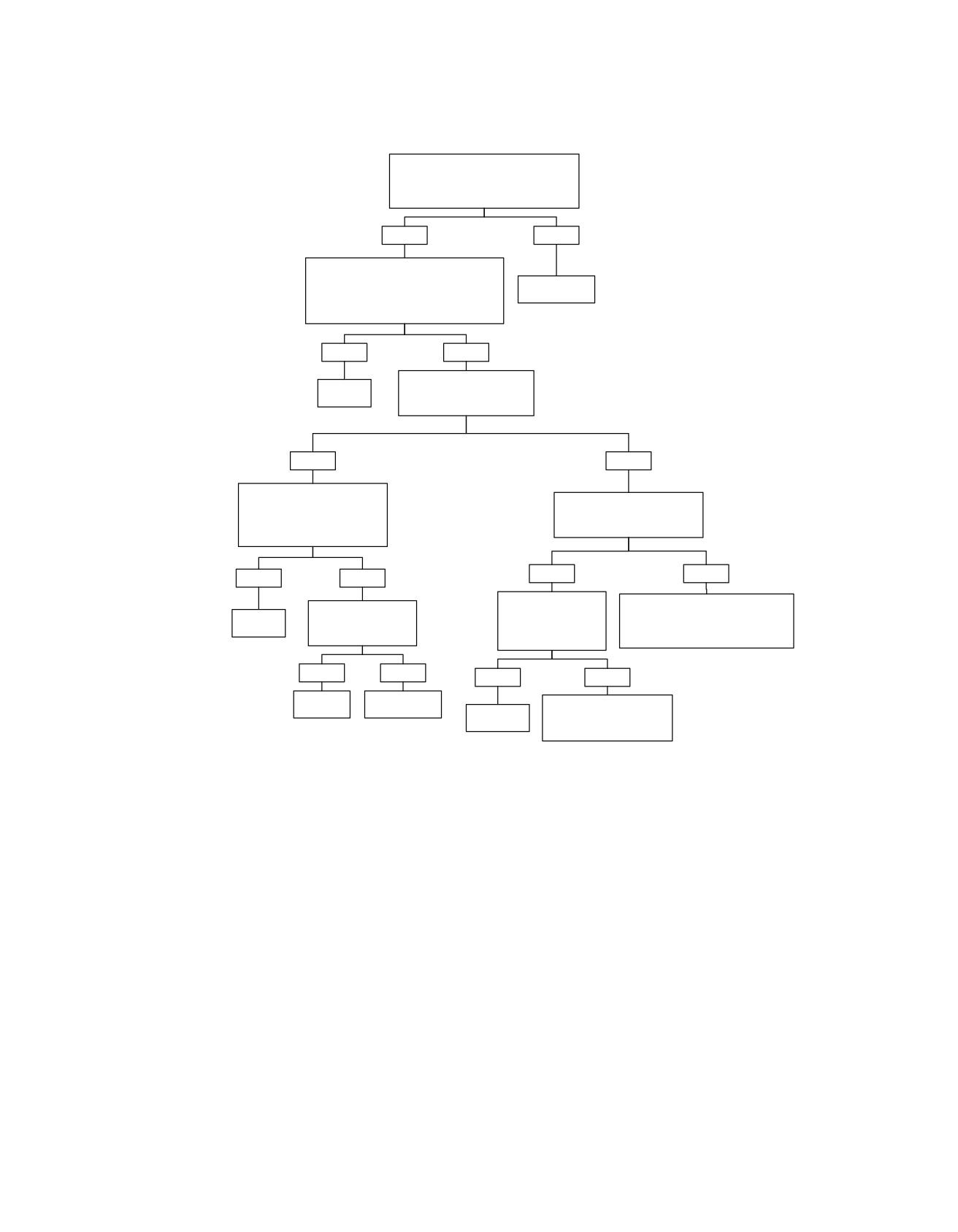
Turn Signal Error 3A Flash at Double Normal Rate, All Bulbs Working
Determine correct part number for
all installed turn signal bulbs and verify
against parts installed on motorcycle.
Correct parts installed?
YES
NO
Verify that lamps are learned by:
1) Turn ignition off-on.
Replace with
2) Activate left turn lamp for 5 flashes.
correct bulbs.
3) Activate right turn lamp for 5 flashes.
Do the lamps now flash at normal rate?
6820
YES
NO
Check for corrosion on bulbs
System
and/or sockets.
OK.
Corrosion present?
YES
NO
Remove corrosion with a wire
brush. Install ELECTRICAL
Check for corrosion on all lamp
CONTACT LUBRICANT (Part
connection terminals.
No. 99861-02) in bulb sockets.
Corrosion present?
Do lamps flash at normal rate?
YES
NO
YES
NO
Clean corrosion from
Replace Turn Signal Module/Turn
Clean or replace bulb.
System
wires and terminals.
Signal Security Module (TSM/TSSM).
Do lamps flash at
Do lamps flash at
Learn password (if needed) and
OK
normal rate?
normal rate?
perform setup.
6821
6824
YES
NO
YES
NO
System
Replace lamp
Replace TSM/TSSM.
OK.
assembly.
System
Learn password (if needed)
6822
OK.
and perform setup.
6823
6822
6824
fc01321_en
2008 Touring Diagnostics: Appendix E TSM/TSSM (Japan/Korea) E-43
HOME
DTC B0563
E.14
GENERAL
DIAGNOSTICS
Battery Voltage High
Diagnostic Tips
The TSM/TSSM continually checks the battery voltage during
•
This DTC may set when the vehicle is placed on a battery
IGN/OFF and IGN/RUN power modes. If the voltage exceeds
charger, on fast charge, for a long period of time.
16.0 volts for more than 5.0 ±0.5 seconds, the TSM/TSSM sets
•
The TSSM does not illuminate the security lamp when this
Diagnostic Trouble Code (DTC) B0563.
DTC is set.
Diagnostic Notes
See 1.7 CHARGING SYSTEM tests to correct. Problem may
be faulty voltage regulator.
E-44 2008 Touring Diagnostics: Appendix E TSM/TSSM (Japan/Korea)

HOME
DTC B1131,
B1132
E.15
longer than 24 hours, the siren will respond with three
GENERAL
chirps on arming instead of two.
NOTE
•
The internal siren battery may not charge if the vehicle's
This section applies only to those vehicles equipped with the
battery is less than 12.5 volts.
optional security system.
•
If the siren does not chirp two or three times on a valid
Alarm Output Low (DTC B1131) or Alarm
arming command from the TSSM, the siren is either not
Output High (DTC B1132)
connected, not working, or the siren wiring was opened
or shorted while the siren was disarmed.
See Figure E-21. An alarm cycle is activated when the TSSM
is connected, the siren has been armed by the TSSM and a
•
If the siren enters the self-driven mode where it is powered
security event occurs. See E.6 SECURITY SYSTEM FUNC-
from the siren internal nine-volt battery, the turn-signal
TIONS (TSSM ONLY). Under normal armed operation, the
lamps will not alternately flash. If the TSSM activates the
siren input (terminal "2") is driven low by the TSSM to trigger
siren, the turn-signal lamps will flash. If the siren has been
the audible alarm. When the siren input is driven high by the
armed and a security event occurs, and the siren is in self-
TSSM the audible alarm stops.
driven mode, the siren will alarm for 20 to 30 seconds and
then turn off for 5 to 10 seconds. This alarm cycle will be
repeated ten times if the siren is in the self-driven mode.
ed02047
•
If the siren does not stop alarming after it has been armed,
then either the TSSM output or siren input may be shorted
to ground, or the siren vehicle battery connection is open
or shorted to ground, or the siren vehicle ground connec-
tion is open, or a security event has occurred. See
E.6 SECURITY SYSTEM FUNCTIONS (TSSM ONLY) for
a description of alarm functions.
Diagnostic Notes
Each reference number below correlates to a circled number
on the flow chart(s).
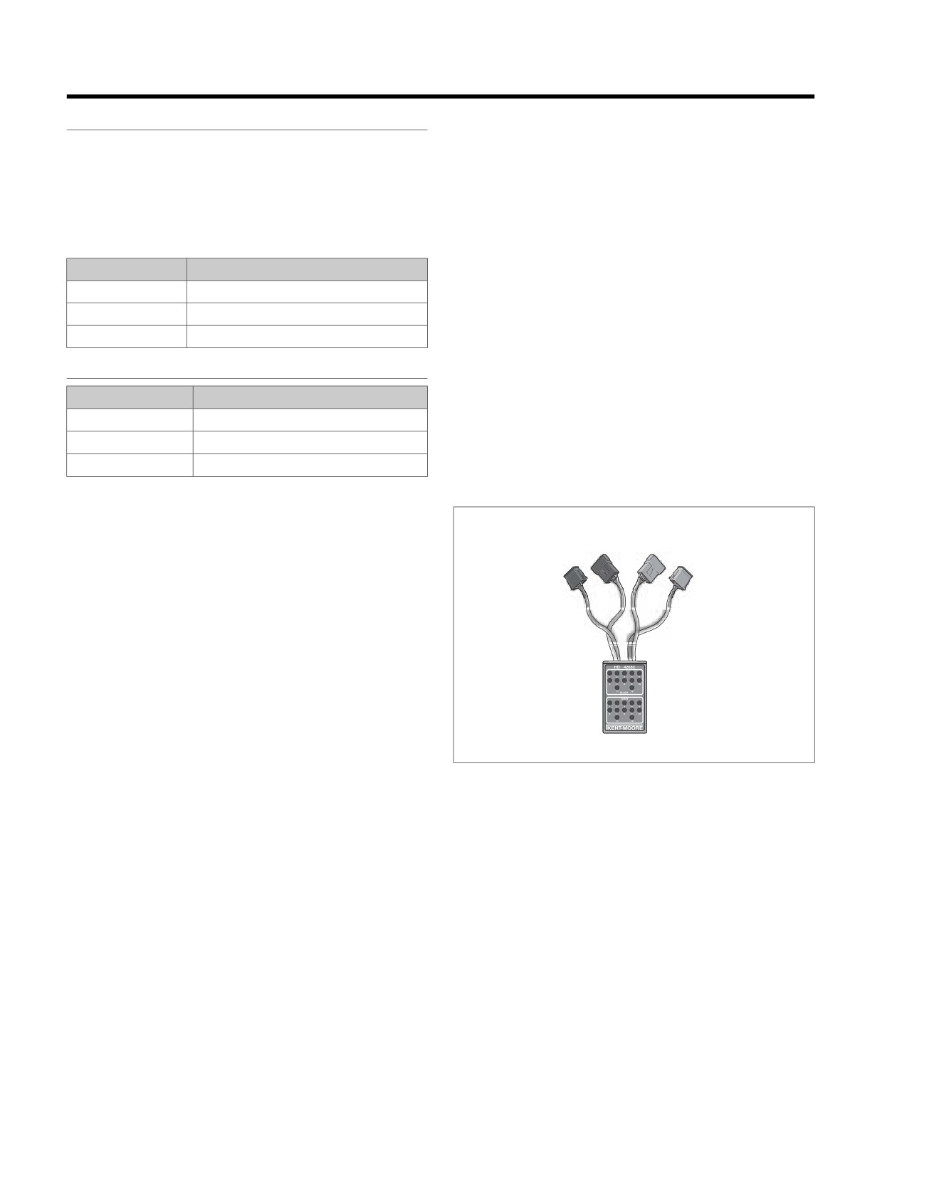
1. Use BREAKOUT BOX (Part No. HD-42682) and HAR-
NESS CONNECTOR TEST KIT (Part No. HD-41404-B),
gray pin probe and patch cord. See E.11 BREAKOUT
Figure E-21. Security Siren
BOX: TSM/TSSM.
2. Use HARNESS CONNECTOR TEST KIT (Part No. HD-
41404-B), gray socket probe and patch cord.
DIAGNOSTICS
3. Having the correct multimeter ohm scale is important for
PART NUMBER
TOOL NAME
this test. Some meters may read infinity for high ohm
HD-41404-B
HARNESS CONNECTOR TEST KIT
values. If this is the case, check your ohm scale and retest.
HD-42682
BREAKOUT BOX
Diagnostic Tips
•
If the siren is armed and the internal siren battery is dead,
shorted, disconnected, or has been charging for a period
2008 Touring Diagnostics: Appendix E TSM/TSSM (Japan/Korea) E-45
HOME
em00036
Security
Siren
[142A]
[142B]
(Optional)
1
1
BN/GY
2
2
LGN/BN
3
3
BK/GN
Ignition
Switch:
FLHR/C/S
Sidecar
Ignition
BAS
[134A]
[134B]
A
B
I
[33A]
Switch:
(Optional)
Signal
[33B]
All Except
C
B
A
A
A
LGN/BN
FLHR/C/S
1
2
3
[33A]
B
B
[33B]
1
2
3
C
C
R
R/BK
R/BK
15 Amp
Ignition
Fuse
R
R
R
-
+
15 Amp
40 Amp
Battery
MAXIFUSE
Battery
Fuse
BK/GN
[30B]
1
2
9
11
12
[30A]
1
2
9
11
12
TSSM
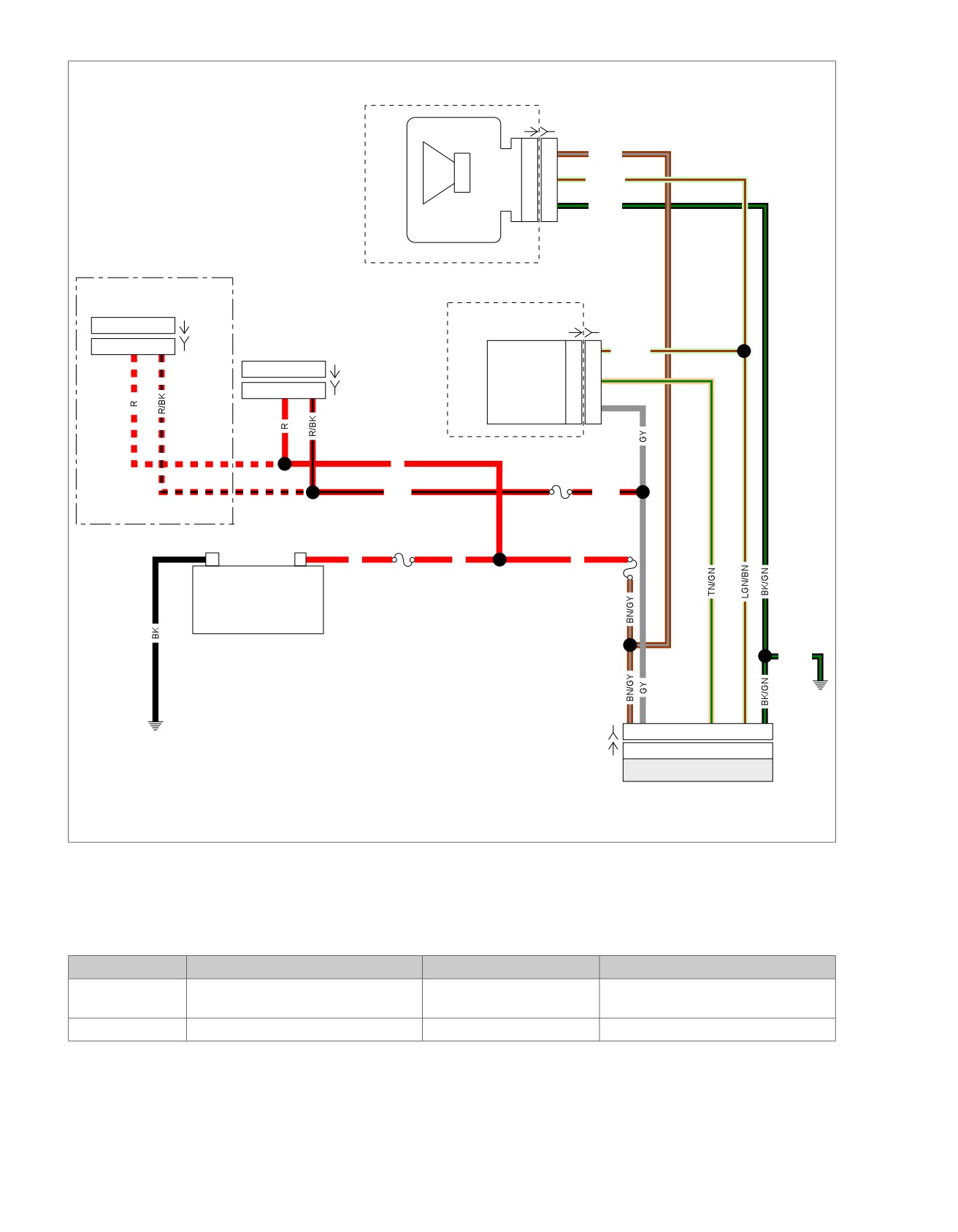
Figure E-22. Siren Circuit
Table E-17. Wire Harness Connectors
NO.
DESCRIPTION
TYPE
LOCATION
[30]
TSSM
12-place Deutsch
Cavity in crossmember at rear of bat-
tery box (under seat)
[142]
Siren
3-place Delphi
Under left side cover (behind fuse box)
E-46 2008 Touring Diagnostics: Appendix E TSM/TSSM (Japan/Korea)
HOME
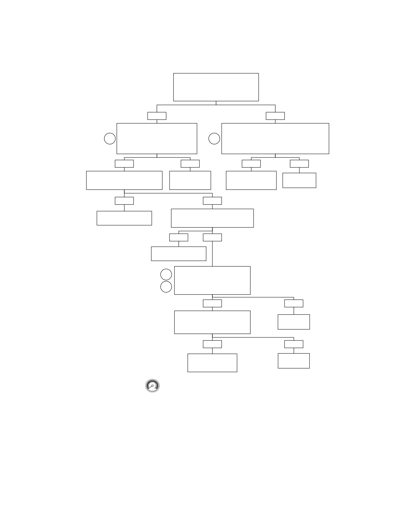
Alarm Output Low: DTC B1131; Alarm Output High: DTC B1132
Check for battery voltage at siren sensor
connector [142B]. With ignition switch turned
to IGNITION, measure voltage between
terminal “3” (BK) and terminal “1" (BN/GY).
Is battery voltage present?
YES
NO
With ignition OFF, check continuity between siren
With ignition OFF, measure resistance
connector [142B] terminal “3” and Breakout Box terminal
between siren connector [142B] terminal
1
1
“12”. Then measure continuity between siren connector
“2” and Breakout Box terminal “11” (Gray).
[142B] Terminal “1” and Breakout Box terminal “1”.
Is resistance less than 1 ohm?
Is continuity present?
YES
NO
YES
NO
Measure resistance between Breakout
Locate and repair
Locate and repair
Repair
Box terminal “11” and chassis ground.
open on (LGN/BN)
short between (BN/GY)
open wire.
Is resistance less than 1 ohm?
wire.
and (BK) wires.
YES
NO
Disconnect TSM/TSSM from Breakout Box.
Locate and repair
Check for voltage on terminal “11”.
grounded (LGN/BN) wire.
Voltage present?
YES
NO
Locate and repair
grounded (LGN/BN) wire.
Disconnect siren from Breakout Box.
2
Measure resistance between siren
connector [142A] Terminal “2” and “3”.
3
Is resistance between 120,000-200,000
ohms with siren disconnected?
YES
NO
Connect siren to a known good
motorcycle. Arm and activate siren
Replace
to verify operation. Disarm siren.
Siren.
Did siren operate correctly?
YES
NO
Replace TSSM. Learn
Replace
password and perform
Siren.
setup.
Clear DTCs using speedometer self diagnostics. See E.10
SPEEDOMETER SELF DIAGNOSTICS. Confirm proper
operation with no check engine lamp.
fc01660_en
2008 Touring Diagnostics: Appendix E TSM/TSSM (Japan/Korea) E-47
HOME
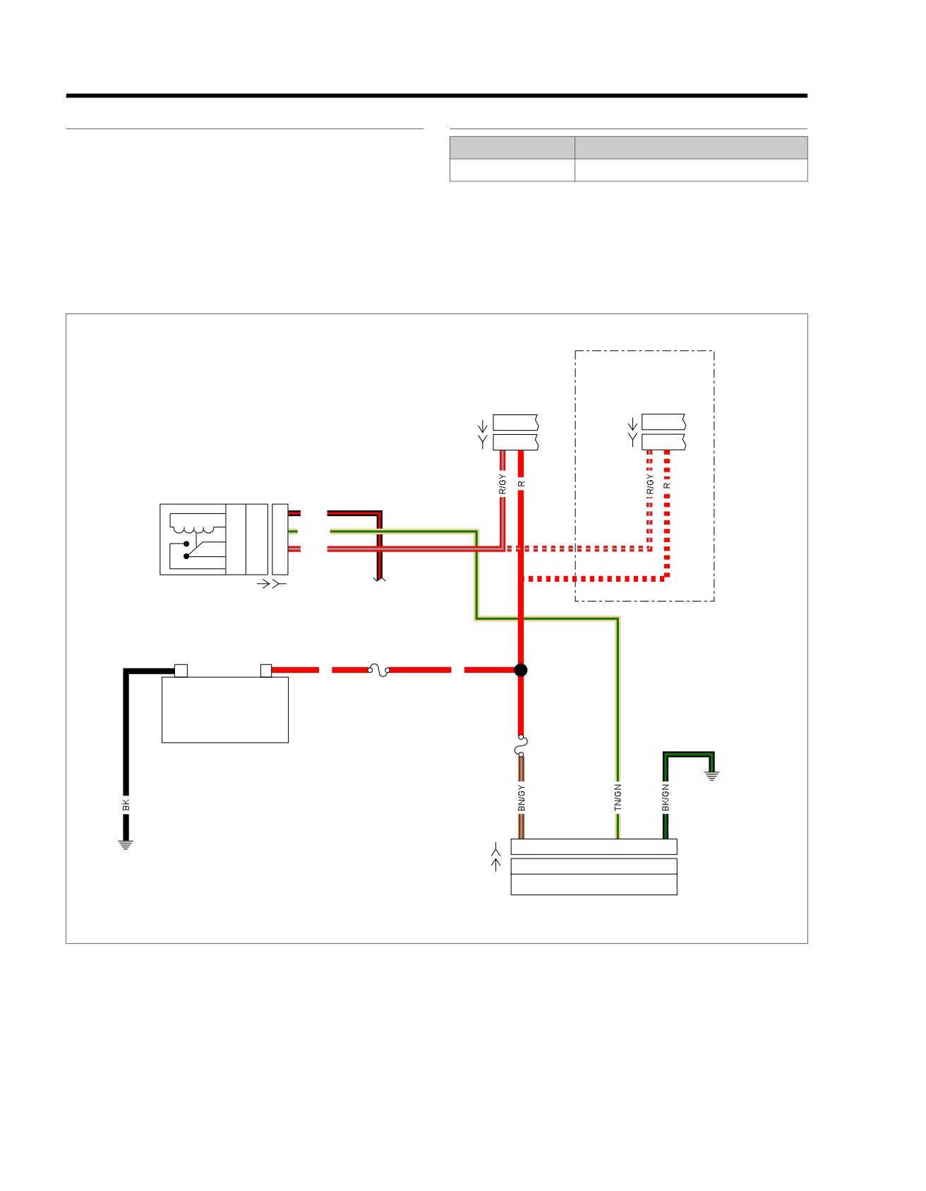
DTC B1134
E.16
GENERAL
DIAGNOSTICS
Starter Output High
PART NUMBER
TOOL NAME
With the TSM/TSSM disarmed, Ignition Switch ON, Engine
HD-42682
BREAKOUT BOX
Stop Switch set to RUN and transmission in neutral of clutch
lever pulled in, the start relay is grounded. Battery voltage is
Diagnostic Notes
applied to the start relay and coil which are grounded through
Each reference number below correlates to a circled number
the TSM/TSSM. This Diagnostic Trouble Code (DTC) is set
on the flow chart(s).
when that ground is not established through the TSM/TSSM.
1. Connect BREAKOUT BOX (Part No. HD-42682) (gray) to
wire harness connector [30] leaving TSM/TSSM discon-
nected. See E.11 BREAKOUT BOX: TSM/TSSM.
em00037
Ignition
Ignition
Switch:
Switch:
All except
FLHR/C/S
FLHR/C/S
A B
1
2
[33A]
[33A]
[33B]
C B
[33B]
1
2
Start Relay
1
86
4H
BK/R
2
85
3G
TN/GN
3
30
3H
R/GY
5
87
4G
To right handlebar
[64-1A] [64-1B]
switch [22]
R
R
-
+
40 Amp
MAXIFUSE
Battery
15 Amp
Battery
Fuse
[30B]
1
9
12
[30A]
1
9
12
TSSM
Figure E-23. Starter/TSSM Circuit
E-48 2008 Touring Diagnostics: Appendix E TSM/TSSM (Japan/Korea)
HOME
Table E-18. Wire Harness Connectors
NO.
DESCRIPTION
TYPE
LOCATION
[30]
TSSM
12-place Deutsch
Cavity in crossmember at rear of bat-
tery box (under seat)
[119]
Start relay
Fuse Block
Fuse block (under left side cover)
2008 Touring Diagnostics: Appendix E TSM/TSSM (Japan/Korea) E-49
HOME
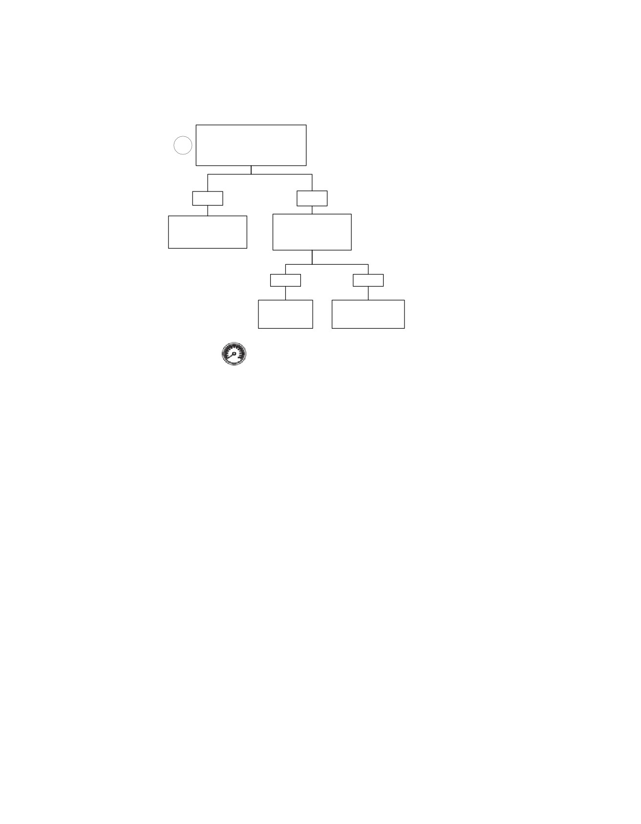
Starter Output High: DTC B1134
Remove Start Relay.
Check for voltage on Breakout Box
1
terminal “9” (Gray).
Voltage present?
YES
NO
Install Start Relay.
Locate and repair
Is voltage present on
short to voltage
Breakout Box terminal
on (TN/GN) wire.
“9" (Gray)?
YES
NO
Replace TSM/TSSM.
Replace
Learn password and
Start Relay.
perform setup.
Clear DTCs using speedometer self diagnostics.
See E. 10 SPEEDOMETER SELF DIAGNOSTICS.
Confirm proper operation with no check engine lamp.
fc01326_en
E-50 2008 Touring Diagnostics: Appendix E TSM/TSSM (Japan/Korea)
HOME
DTC B1135
E.17
GENERAL
NOTE
When DTC B1135 is set, the tip-over engine shutdown, TSSM
Accelerometer Fault: B1135
tamper alarm and bank angle sensors are disabled. The
Diagnostic Trouble Code (DTC) B1135 indicates a failure which
security lamp will also illuminate when this code is set.
requires replacement of the TSM/TSSM.
2008 Touring Diagnostics: Appendix E TSM/TSSM (Japan/Korea) E-51
HOME
DTC B1151,
B1152, B1153
E.18
sidecar learning is disabled using DIGITAL TECHNICIAN,
GENERAL
or the bank angle sensor is reinstalled.
Sidecar Bank Angle Sensor (BAS)
•
The software is designed to prevent the TSM/TSSM from
These Diagnostic Trouble Codes (DTCs) are set when a
switching to sidecar mode unless the entire system is
TSM/TSSM is configured for sidecar use and a fault is detected
operating properly (no DTCs set).
with the sidecar Bank Angle Sensor (BAS).
•
The bank angle sensor cannot be detected when the
security function is in the alarm mode (that is, lights
Table E-19. Code Description
flashing, siren sounding).
DTC
DESCRIPTION
•
A sidecar tip-over event cannot be detected when the
security function is in the alarm mode (that is, lights
B1153
Sidecar BAS high
flashing, siren sounding).
B1151
Sidecar BAS short to ground
•
A short to ground fault cannot be detected when the
B1152
Sidecar BAS short to battery
security function is in the alarm mode (that is, lights
flashing, siren sounding).
DIAGNOSTICS
•
A short to battery fault cannot be detected unless the
PART NUMBER
TOOL NAME
security function is in the alarm mode (that is, lights
HD-41404-B
HARNESS CONNECTOR TEST KIT
flashing, siren sounding).
HD-42682
BREAKOUT BOX
•
An out-of-range fault cannot be detected when the security
function is in the alarm mode (that is, lights flashing, siren
HD-44750
DIGITAL TECHNICIAN
sounding).
Diagnostic Tips
•
The smart siren cannot be disarmed when the ignition
ed02037
switch is turned to IGNITION and a bank angle sensor is
installed. If the ignition switch triggers the security alarm,
then the switch must be turned off to disarm the siren.
•
Use DIGITAL TECHNICIAN (Part No. HD-44750) to ensure
sidecar learn.
•
Ensure that no other circuits are tied to terminal "11" of
the TSM/TSSM.
•
If a sidecar is installed without the bank angle sensor kit
then the TSM/TSSM will continue to operate in Solo mode
on a sidecar bike.
•
If the bank angle sensor is removed without disabling
sidecar learning then the TSM/TSSM will set a DTC until
Figure E-24. Breakout Box (Part No. HD-42682)
E-52 2008 Touring Diagnostics: Appendix E TSM/TSSM (Japan/Korea)
HOME
Diagnostic Notes
ed02054
Each reference number below correlates to a circled number
on the flow chart(s).
1. Use BREAKOUT BOX (Part No. HD-42682) and HAR-
NESS CONNECTOR TEST KIT (Part No. HD-41404-B),
gray pin probe and patch cord. 3.12 BREAKOUT BOX:
TSM/HFSM
2. Use HARNESS CONNECTOR TEST KIT (Part No. HD-
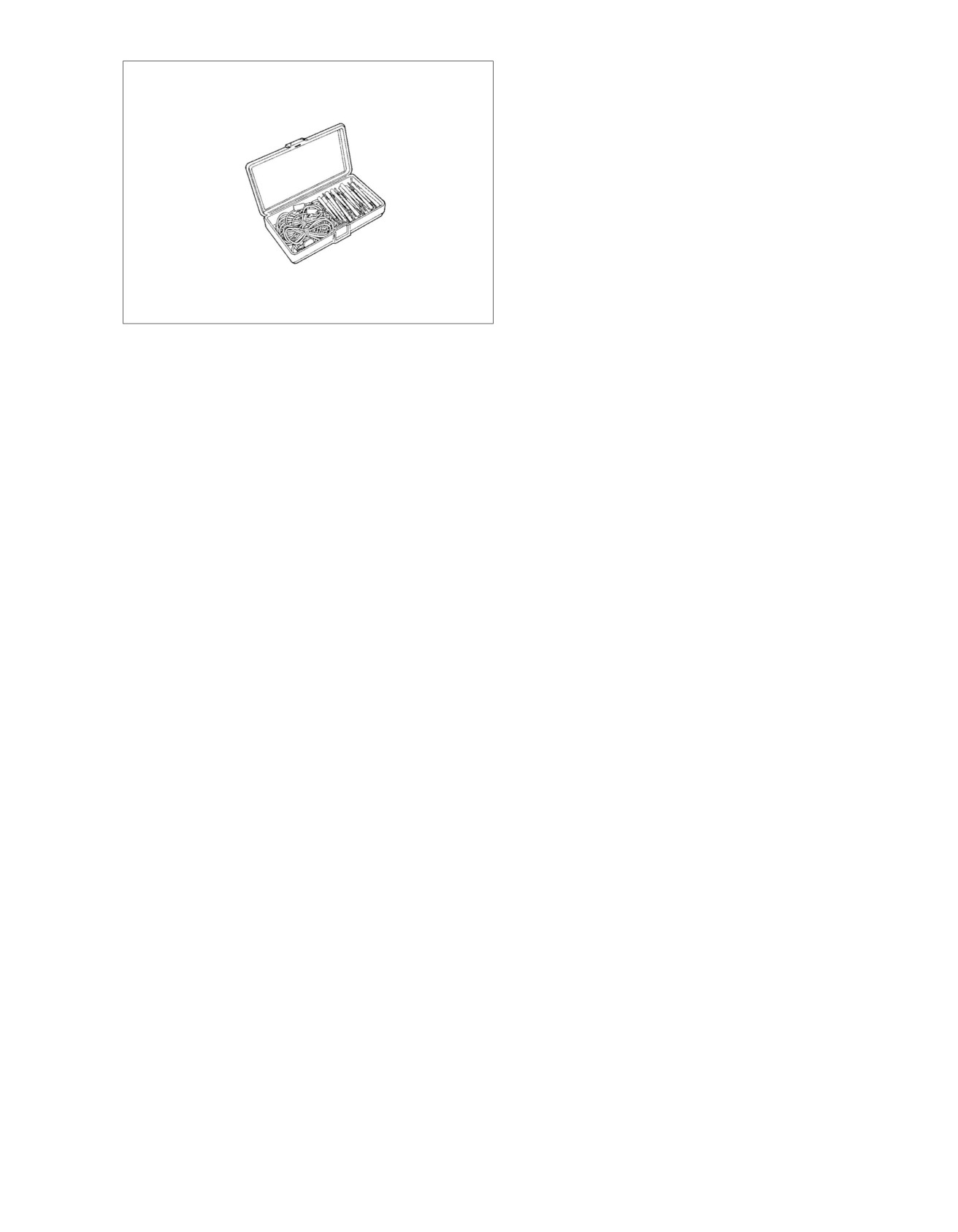
41404-B), gray pin probe and patch cord.
Figure E-25. Harness Connector Test Kit (Part No.
HD-41404-B)
2008 Touring Diagnostics: Appendix E TSM/TSSM (Japan/Korea) E-53
HOME
em01179
Security
Siren
[142A]
[142B]
(optional)
1
1
BN/GY
2
2
LGN/BN
3
3
BK/GN
Ignition
Switch:
FLHR/C/S
A
B
I
[33A]
C
B
A
[33B]
Ignition
Switch:
All except
FLHR/C/S
1
2
3
[33A]
1
2
3
[33B]
2
1
[222B]
2
1
[222A]
To 15 amp
ignition fuse
BK
R
R
R
BN/GY
-
+
40 Amp
15 Amp
MAXIFUSE
Battery
Fuse
Battery
[30A]
1
11
12
[30B]
1
11
12
TSM/TSSM/HFSM
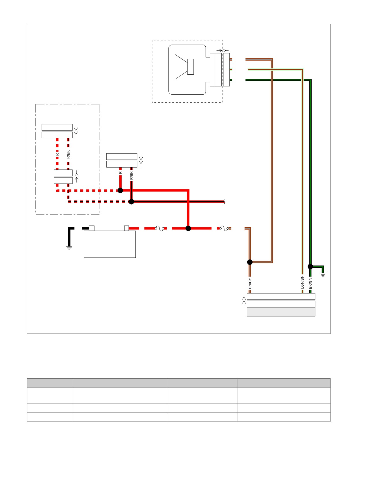
Figure E-26. Siren Circuit
Table E-20. Wire Harness Connectors
NO.
DESCRIPTION
TYPE
LOCATION
[30]
TSM/TSSM
12-place Deutsch
Cavity in crossmember at rear of bat-
tery box (under seat
[134]
Sidecar BAS
3-place Packard
Under seat
[142]
Siren
3-place Packard
Under left side cover (behind fuse box)
E-54 2008 Touring Diagnostics: Appendix E TSM/TSSM (Japan/Korea)
HOME
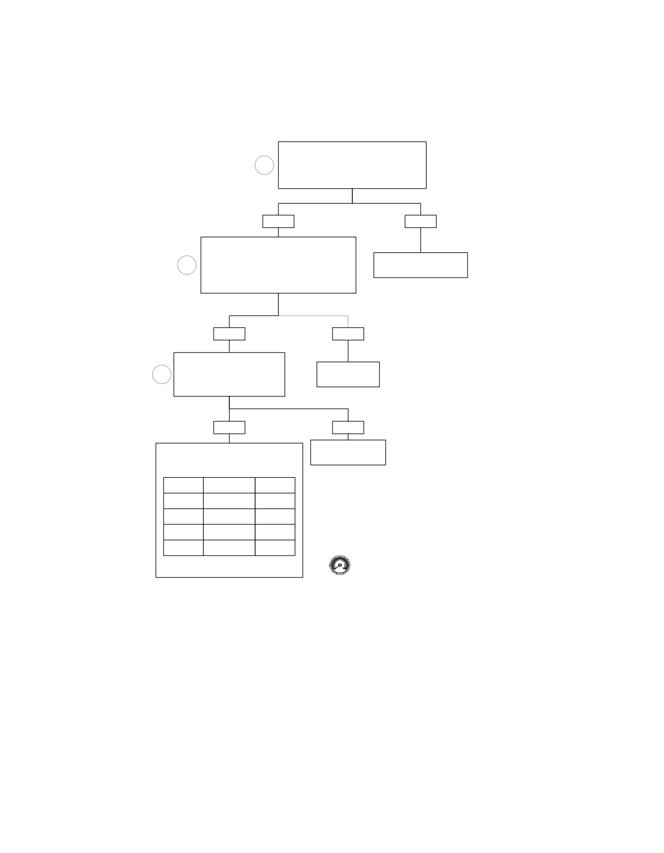
Sidecar BAS Short-to-Ground: DTC B1151; Sidecar BAS Short-to-Battery: DTC B1152;
Sidecar BAS High: DTC B1153
Disarm security system. Connect Breakout
Box to Connector [30]. Turn Ignition Switch to
1
IGNITION. Measure voltage between terminal
“2” (Gray) and “12” (Gray).
Battery voltage present?
YES
NO
With Ignition OFF, check continuity between
connector [134B] terminal “C” and Breakout Box
terminal “2” (Gray). Then measure continuity
See Will Not Flash, 4-Way
2
between connector [134B] terminal “A” and
Flashers Inoperative.
Breakout Box terminal “11" (Gray).
Continuity present?
YES
NO
Measure resistance between
connector [134B] terminal “B” and
Locate and repair
2
Breakout Box terminal “9” (Gray).
open wire.
Resistance less than 1 ohm?
YES
NO
Locate and repair
Jumper terminals “9” (Gray) and “12”
open on (TN/GN) wire.
(Gray) on Breakout Box and then
check voltage on terminal “11” (Gray).
DTCs
Voltage
Condition
Set
Short to
<0.25
Ground
Yes
Short to VBAT
>8.0
Yes
Disabled
>5.5
No
0.25
-1.5
RUN
No
Clear DTCs using speedometer self diagnostics.
Replace Sidecar BAS if voltage
See E.10 SPEEDOMETER SELF DIAGNOSTICS.
is out of RUN range.
Confirm proper operation with no check engine lamp.
fc01327_en
2008 Touring Diagnostics: Appendix E TSM/TSSM (Japan/Korea) E-55
HOME
DTC B1154,
B1155
E.19
1. Connect BREAKOUT BOX (Part No. HD-42682) to TSSM.
GENERAL
See E.11 BREAKOUT BOX: TSM/TSSM.
Diagnostic Trouble Codes (DTCs) B1154 and B1155 may occur
2. If DTC is current (lamp) on continuously, clear codes return
if the motorcycle is ridden with the clutch disengaged (pulled
during operation), replace HFSM. If DTC is historic, check
in) at speeds greater than 10 MPH (16 KMH)for more than 60
for intermittents.
seconds (as in coasting down a long mountain road).
3. A reading of several hundred ohms is normal due to the
DIAGNOSTIC NOTES
neutral indicator lamp (LED).
PART NUMBER
TOOL NAME
HD-42682
BREAKOUT BOX
Each reference number below correlates to a circled number
on the flow chart(s).
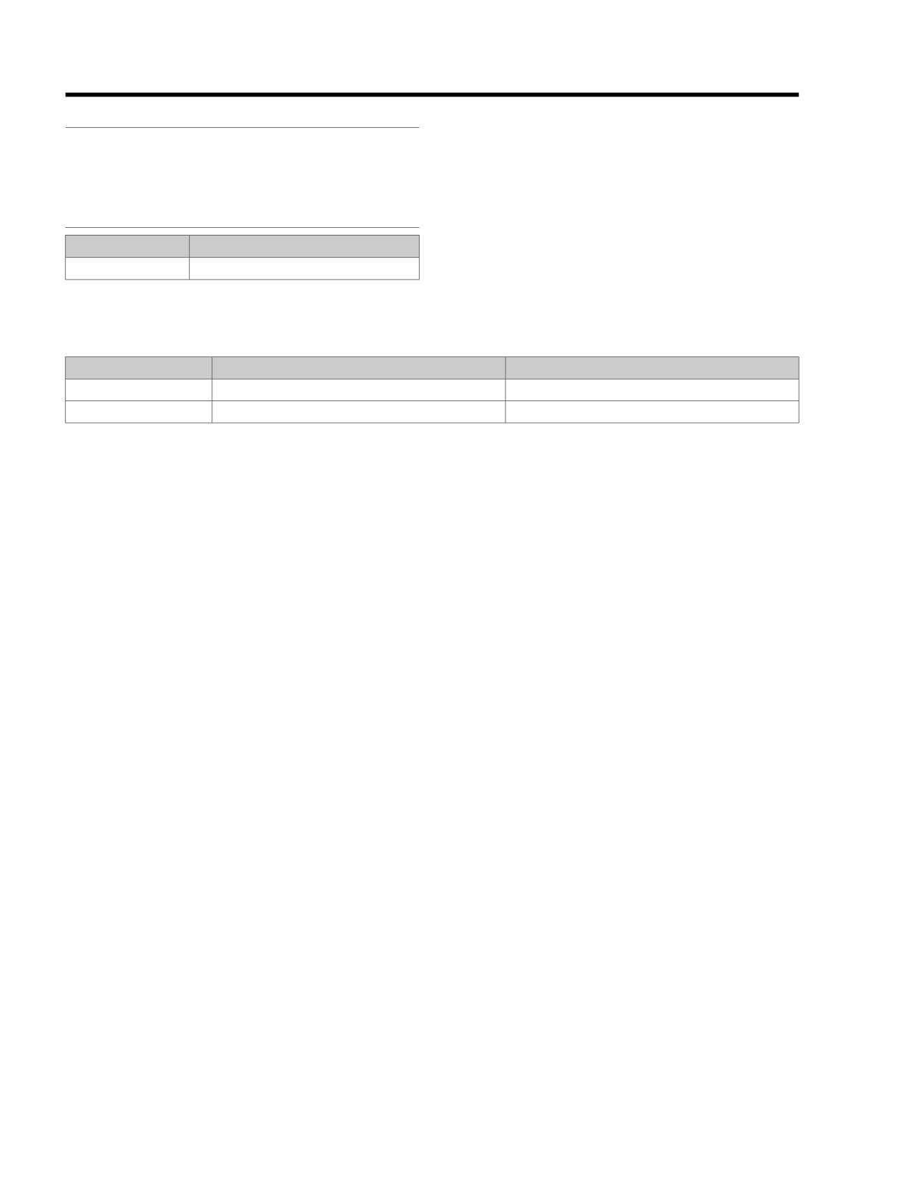
Table E-21. Clutch/Neutral Switch DTCs
DTC
DESCRIPTION
GO TO
B1154
Clutch switch short-to-ground
Clutch Switch Short-to-Ground: DTC B1154
B1155
Neutral switch short-to-ground
Neutral Switch Short-to-Ground: DTC B1155
E-56 2008 Touring Diagnostics: Appendix E TSM/TSSM (Japan/Korea)
HOME
em00054
Turn Signal Module/
Turn Signal Security
Module
TSM/TSSM
Neutral switch
4
4
TN
Clutch switch
10
10
BK/R
BK/GN
[30A] [30B]
Rear
GND2
(Clean)
[24A] [24B]
BK/R
7
7
BK/R
BK
8
8
BK/GN
Front GND
Stud (Dirty)
Clutch Switch
BK
(GND1A)
Hand Controls
To
instrument
O
TN
Left
fuse
[21A]
6
7
[21A]
6
7
B
A
[131]
BK
Neutral
Switch
Neutral
Indicator
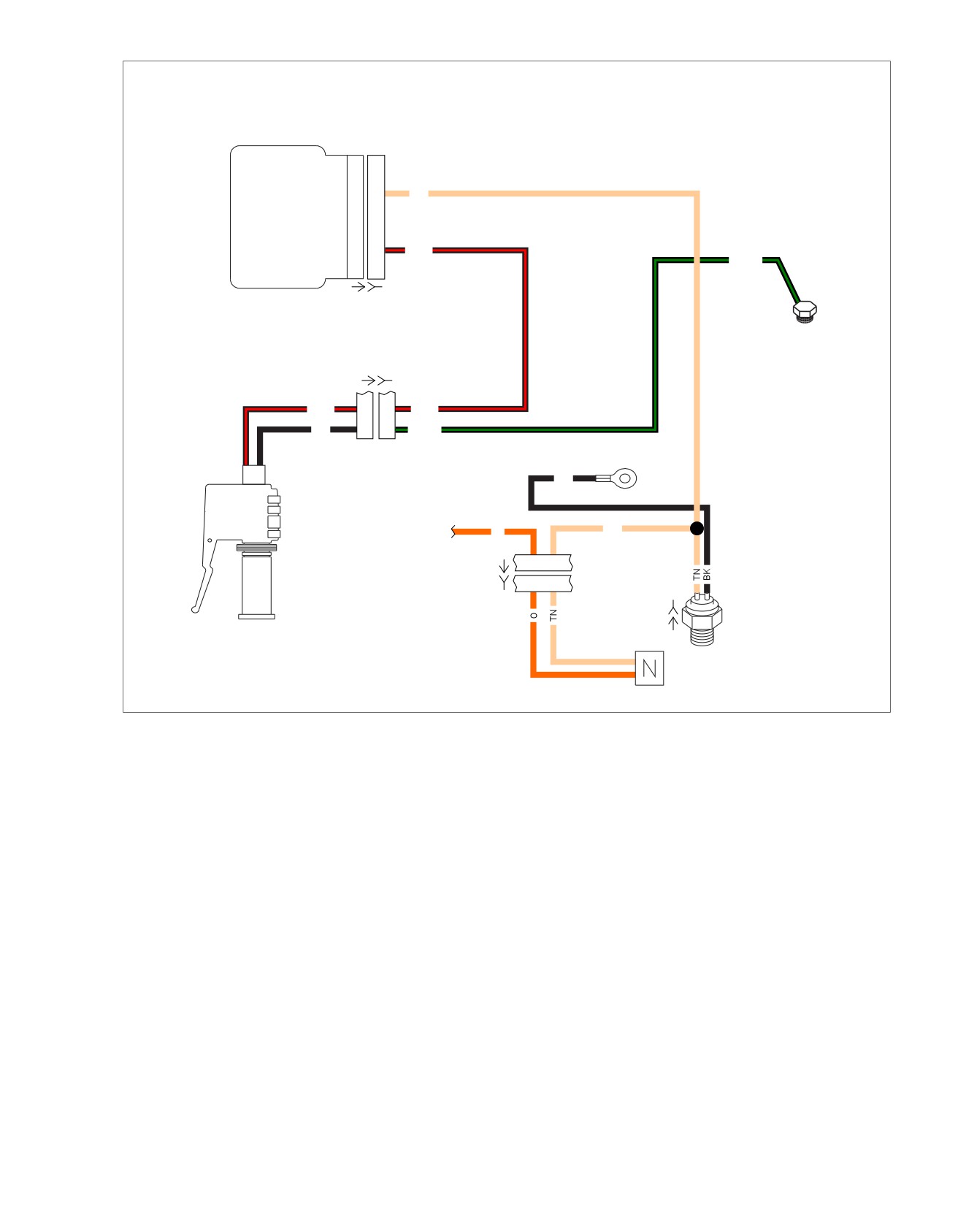
Figure E-27. Clutch and Neutral Interlock Circuits (FLHR/C/S)
2008 Touring Diagnostics: Appendix E TSM/TSSM (Japan/Korea) E-57
HOME
em00055
Turn Signal Module/
Turn Signal
Security Module
TSM/TSSM
Neutral switch
4
4
TN
BK/GN
Clutch switch
10
10
BK/R
[30A] [30B]
Rear
[2A] [2B]
GND2
[24A] [24B]
(Gray)
(Clean)
BK/GN
12
12
BK/GN
BK/R
7
7
BK/R
BK/R
11
11
BK/R
BK
12
12
BK/GN
13
13
14
14
15
15
16
16
Front GND
Stud (Dirty)
16-Way on all except FLHTP
BK
12-Way on FLHTP
Clutch Switch
[GND1A]
To
TN
instrument
O
fuse
[21A]
6
7
[21B]
6
7
B
A
[131]
Left Hand
(BK)
Controls
Neutral
Switch
Neutral
Indicator
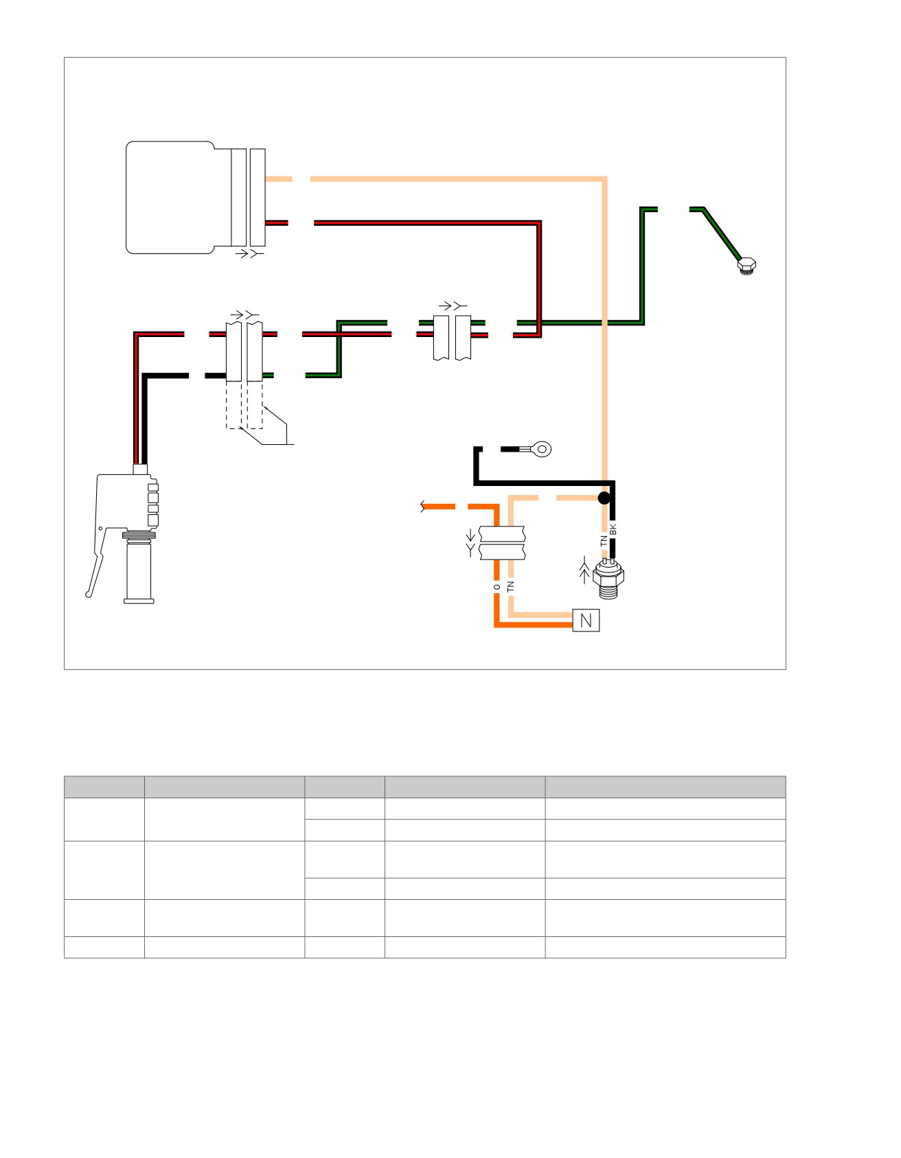
Figure E-28. Clutch and Neutral Interlock Circuits (FLHX, FLHT/C/U, FLTR)
Table E-22. Wire Harness Connectors
NO.
DESCRIPTION
MODEL
TYPE
LOCATION
[21]
Indicator lamps
FLHR/C/S
8-place Delphi
Under console
FLHT/C/U/R
8-place Delphi
Inner fairing - above radio
[24]
Left handlebar switches
FLHR/C/S
8-place Molex (gray)
Inside headlamp nacelle - fork stem nut
lock plate
FLHT/C/U/R
16-place Molex (gray)
Inner fairing - left fairing support brace
[30]
TSM/TSSM
All
12-place Deutsch
Crossmember at rear of battery box (under
seat)
[131]
Neutral switch
All
Post terminals
Top of transmission (right side)
E-58 2008 Touring Diagnostics: Appendix E TSM/TSSM (Japan/Korea)
HOME
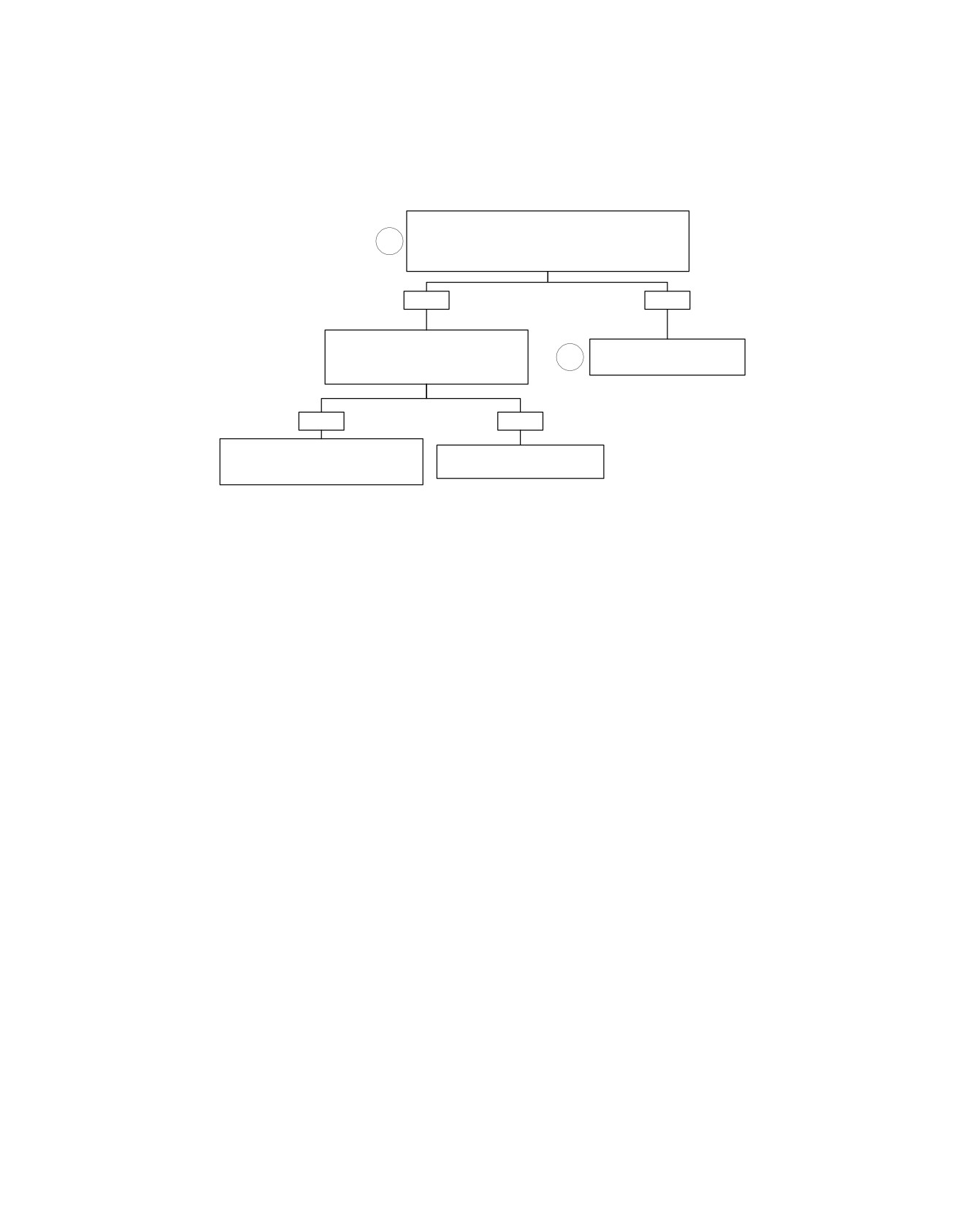
Clutch Switch Short-to-Ground: DTC B1154
Connect Breakout Box HD-42682 to the main harness, leaving
the connector [30] disconnected. Measure continuity between
1
terminal “10” (Gray)(+) and terminal “12” (Gray)(-).
Is continuity present?
YES
NO
Disconnect connector [24]. Measure
continuity between terminal 10 (Gray)(+)
Replace TSSM. Learn password
2
and terminal “12” (Gray)(-) on Breakout Box.
and perform set-up.
Is continuity present?
6791
YES
NO
Locate and repair short to ground on (BK/R)
Locate and repair short to ground in
wire in main wiring harness between
left handlebar switch wiring.
connectors [30B] and [24B].
fc01328_en
5861
5861
2008 Touring Diagnostics: Appendix E TSM/TSSM (Japan/Korea) E-59
HOME
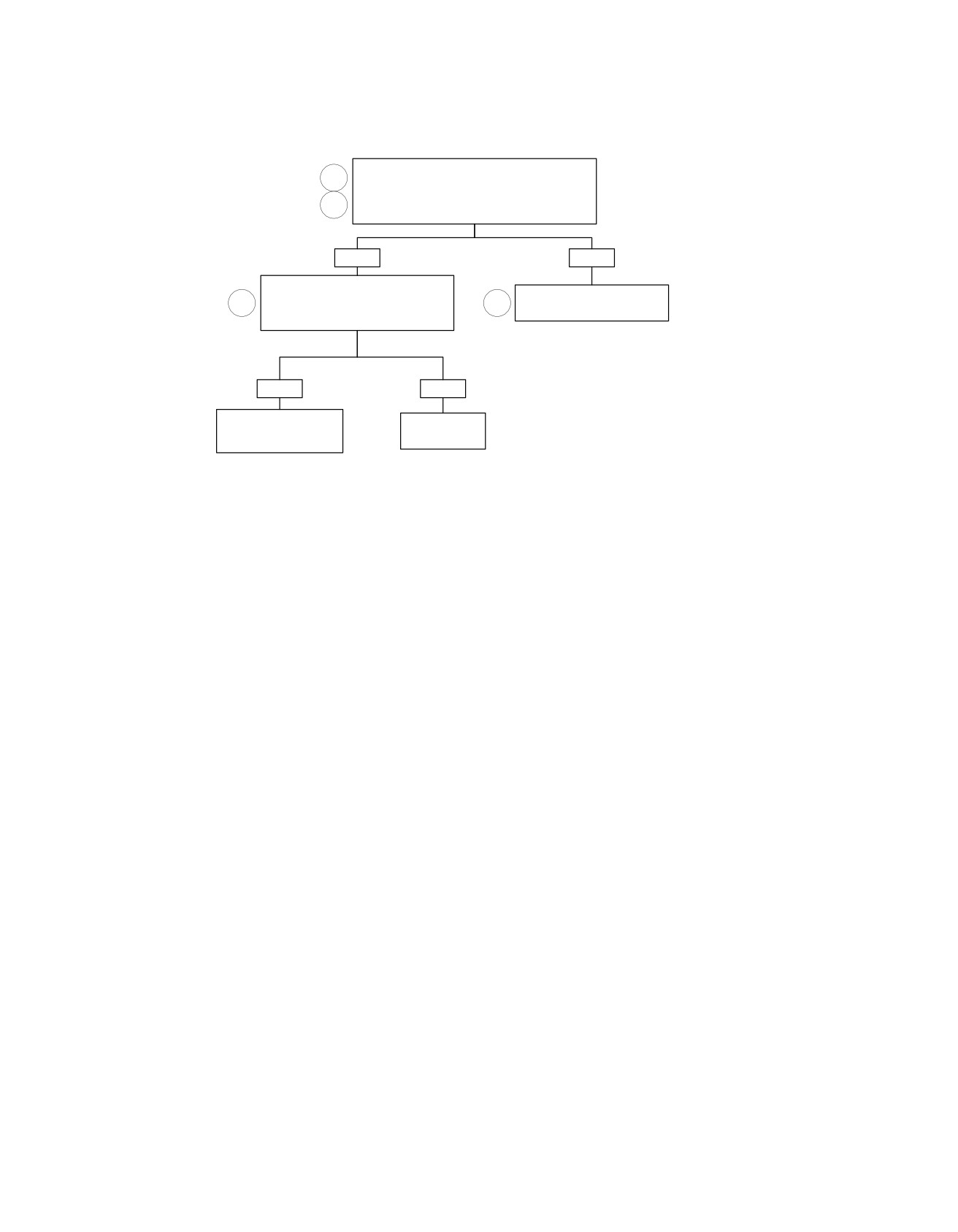
Neutral Switch Short-to-Ground: DTC B1155
With the transmission in 1st or 2nd gear, connect
1
Breakout Box HD-42682 to the main harness, leaving
the TSSM disconnected. Measure continuity
3
between terminal “4” (Gray) and terminal “12” (Gray).
Is continuity (less than 10 ohms) present?
YES
NO
Disconnect Neutral Switch [131]. Measure
continuity between terminal “4” (Gray) and
Replace TSSM. Learn password
3
2
terminal “12" (Gray) on Breakout Box.
and perform set-up.
Is continuity (less than 10 ohms) present?
6791
YES
NO
Locate and repair short to
Replace Neutral
ground on (TN) wire in
fc01329_en
Switch.
main wiring harness.
5862
5157
E-60 2008 Touring Diagnostics: Appendix E TSM/TSSM (Japan/Korea)