Harley Davidson 2008 Touring Models. Electrical Diagnostics Manual - page 32
TABLE OF CONTENTS
SUBJECT
PAGE NO.
A.1 AMP 1-PLACE CONNECTORS
A-1
A.2 AMP MULTILOCK CONNECTORS
A-3
A.3 DELPHI CONNECTORS
A-8
A.4 DEUTSCH 1-PLACE ELECTRICAL CONNECTORS
A-10
A.5 DEUSCH ELECTRICAL CONNECTORS
A-11
A.6 DEUTSCH STANDARD TERMINALS
A-15
A.7 DEUTSCH MINI-TERMINAL CRIMPS
A-16
A.8 DEUTSCH SOLID BARREL TERMINALS
A-17
A.9 RELAY AND FUSE BLOCKS
A-19
A.10 150 METRI-PACK CONNECTORS
A-20
A.11 280 METRI-PACK CONNECTORS
A-22
A.12 480 METRI-PACK CONNECTORS
A-24
A.13 630 METRI-PACK CONNECTORS
A-25
A.14 800 METRI-PACK CONNECTORS
A-26
A.15 METRI-PACK TERMINALS
A-28
A.16 MOLEX CONNECTORS
A-30
A.17 PACKARD ECM CONNECTOR
A-32
A.18 PACKARD MICRO-64 CONNECTORS
A-34
A.19 SEALED SPLICE CONNECTORS
A-37
NOTES
HOME
AMP 1-PLACE CONNECTORS
A.1
AMP 1-PLACE CONNECTOR REPAIR
sm00011
PART NUMBER
TOOL NAME
HD-38125-7
PACKARD TERMINAL CRIMPER
HD-39621-27
SOCKET TERMINAL TOOL
2
HD-39621-28
PIN TERMINAL REMOVER
General
1
Obtain the necessary tools to repair the connector or terminals.
For terminal crimping, use the PACKARD TERMINAL
CRIMPER (Part No. HD-38125-7).
Separating Pin and Socket Housings
4
Bend back the ears on the pin housing slightly and separate
the pin and socket halves of the connector.
Mating Pin and Socket Housings
Push the pin and socket halves of the connector together until
3
the latches click.
6
Removing Socket Terminals
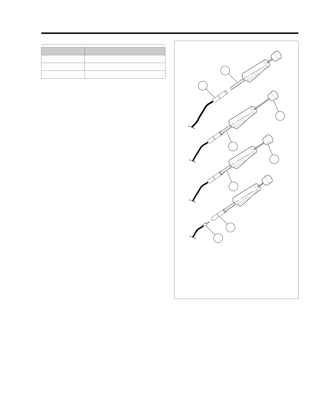
1. See Figure A-1. Grasp the lead on the wire end of the
socket housing (1) and push the terminal forward toward
the mating end of the connector until it stops. This will
disengage the locking tang from the groove in the con-
5
nector.
2. Fit the barrel (2) of the SOCKET TERMINAL TOOL (Part
No. HD-39621-27) over the socket.
3. While rotating the tool slightly, push until it bottoms (3) in
the socket housing.
8
4. Allow the plunger (4) to "back out" of the handle.
5. Holding the socket housing while keeping the tool firmly
7
bottomed (5), depress the plunger (6). The terminal (7)
pops out the wire end of the connector.
1.
Socket housing
NOTE
2.
Barrel
If the terminal is not released from the socket housing, then
3.
Barrel bottomed in connector
the terminal was not pushed forward far enough before place-
4.
Plunger "backed out"
ment of the tool or the tool was not bottomed in the connector
5.
Hold barrel bottomed
housing.
6.
Plunger pressed
7.
Socket terminal
Installing Socket Terminal
8.
Connector lip
1. Note the lip at the middle of the socket housing. One side
Figure A-1. Socket Terminal Tool (HD-39621-27)
of the lip is flat while the other side is tapered. Insert the
wire terminal into the socket housing on the flat (lip) side.
2. Push the lead into the socket housing until it stops. A click
Removing Pin Terminal
is heard when the terminal is properly seated.
1. Grasp the lead on the wire end of the pin housing and
3. Gently tug on the lead to verify that the terminal is locked
push the terminal forward toward the mating end of the
in place.
connector until it stops. This will disengage the locking
tang from the groove in the connector.
2008 Touring Diagnostics: Appendix A Connector Repair A-1
HOME
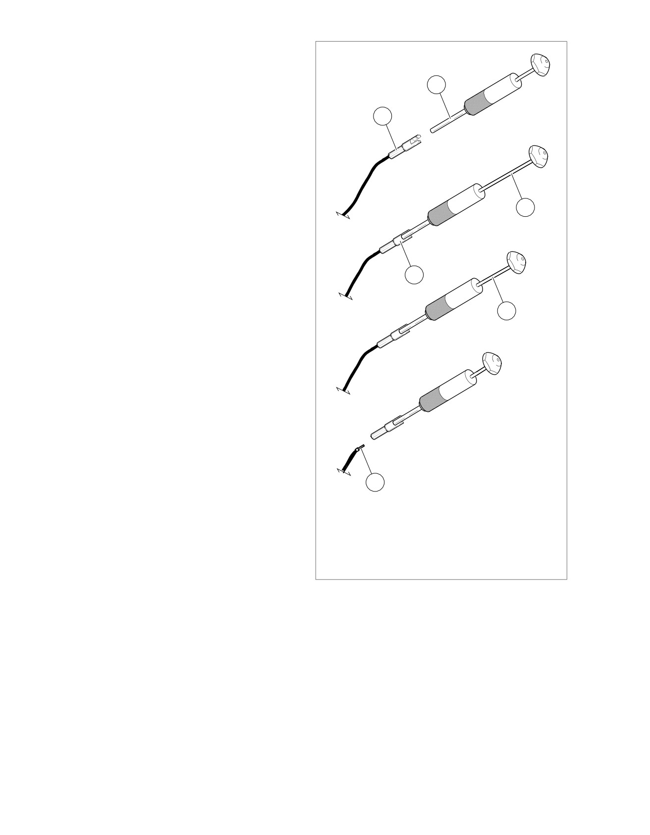
2. See Figure A-2.
sm00012
a. Fit the barrel of the PIN TERMINAL REMOVER (Part
No. HD-39621-28) over the pin, and while rotating
the tool slightly, push until it bottoms in the housing.
2
Allow the plunger to "back out" of the handle.
b. Holding the pin housing while keeping the tool firmly
1
bottomed, depress the plunger. The terminal pops
out the wire end of the connector.
NOTE
If the terminal is not released from the pin housing, then the
terminal was not pushed forward far enough before placement
of the tool or the tool was not bottomed in the connector
housing.
4
Installing Pin Terminal
1. Push the lead into the pin housing until it stops. A click is
heard when the terminal is properly seated.
2. Gently tug on the lead to verify that the terminal is locked
3
in place.
5
6
1. Pin housing
2. Barrel
3. Barrel bottomed in connector
4. Plunger backed out of the handle
5. Depressed plunger
6. Pin terminal
Figure A-2. AMP Pin Terminal Remover (HD-39621-28)
A-2 2008 Touring Diagnostics: Appendix A Connector Repair
HOME
AMP MULTILOCK CONNECTORS
A.2
AMP MULTILOCK CONNECTOR REPAIR
sm00002
PART NUMBER
TOOL NAME
2
HD-41609
AMP MULTILOCK CRIMPER
3
General
4
AMP Multilock connectors are found between wire harnesses
and component wiring and may be either floating or anchored
to the frame with attachment clips.
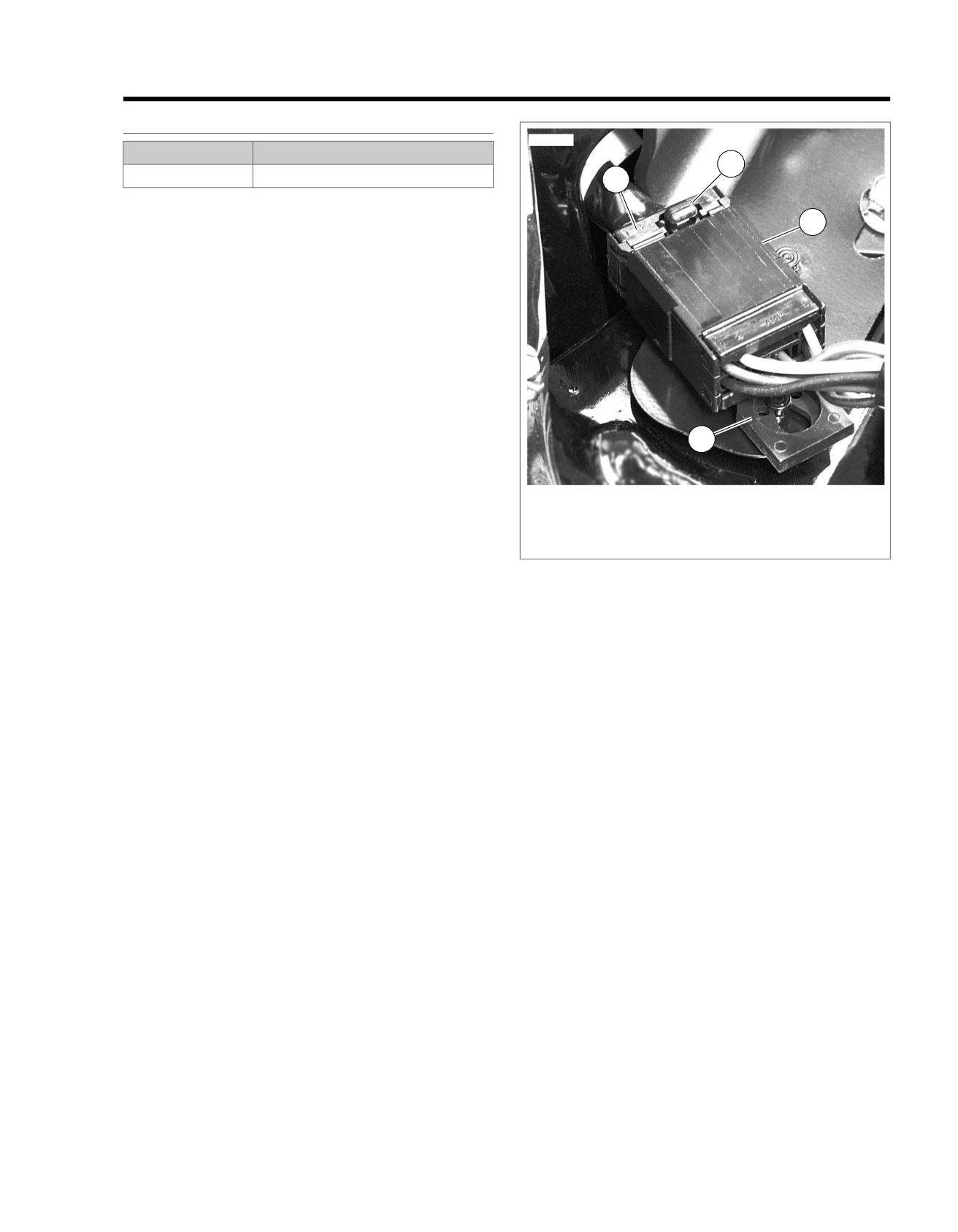
See Figure A-3. Attachment clips (1) on the pin housings are
fitted to T-studs on the motorcycle frame. The T-studs identify
OE connector locations. To maintain serviceability, always
return connectors to OE locations after service.
Obtain the necessary tools to repair the connector and ter-
minals.
NOTE
For terminal crimping use the AMP MULTILOCK
CRIMPER (Part No. HD-41609).
1
Separating Pin and Socket Housings
1. If necessary, slide connector attachment clip T-stud to the
1. Attachment clip
large end of the opening.
2. Release button
3. Socket housing
2. See Figure A-3. Depress the release button (2) on the
4. Pin housing
socket terminal side of the connector and pull the socket
housing (3) out of the pin housing (4).
Figure A-3. AMP Multilock Connector
Mating Pin and Socket Housings
1. Hold the housings to match wire color to wire color.
Removing Terminals from Housing
2. Insert the socket housing into the pin housing until it snaps
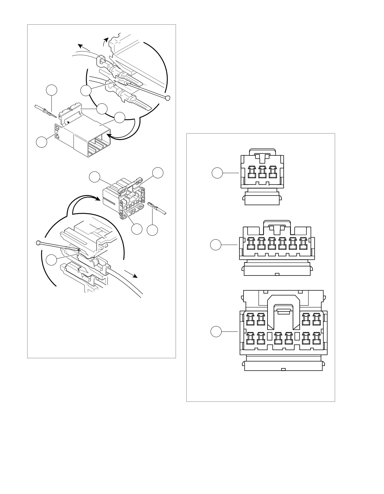
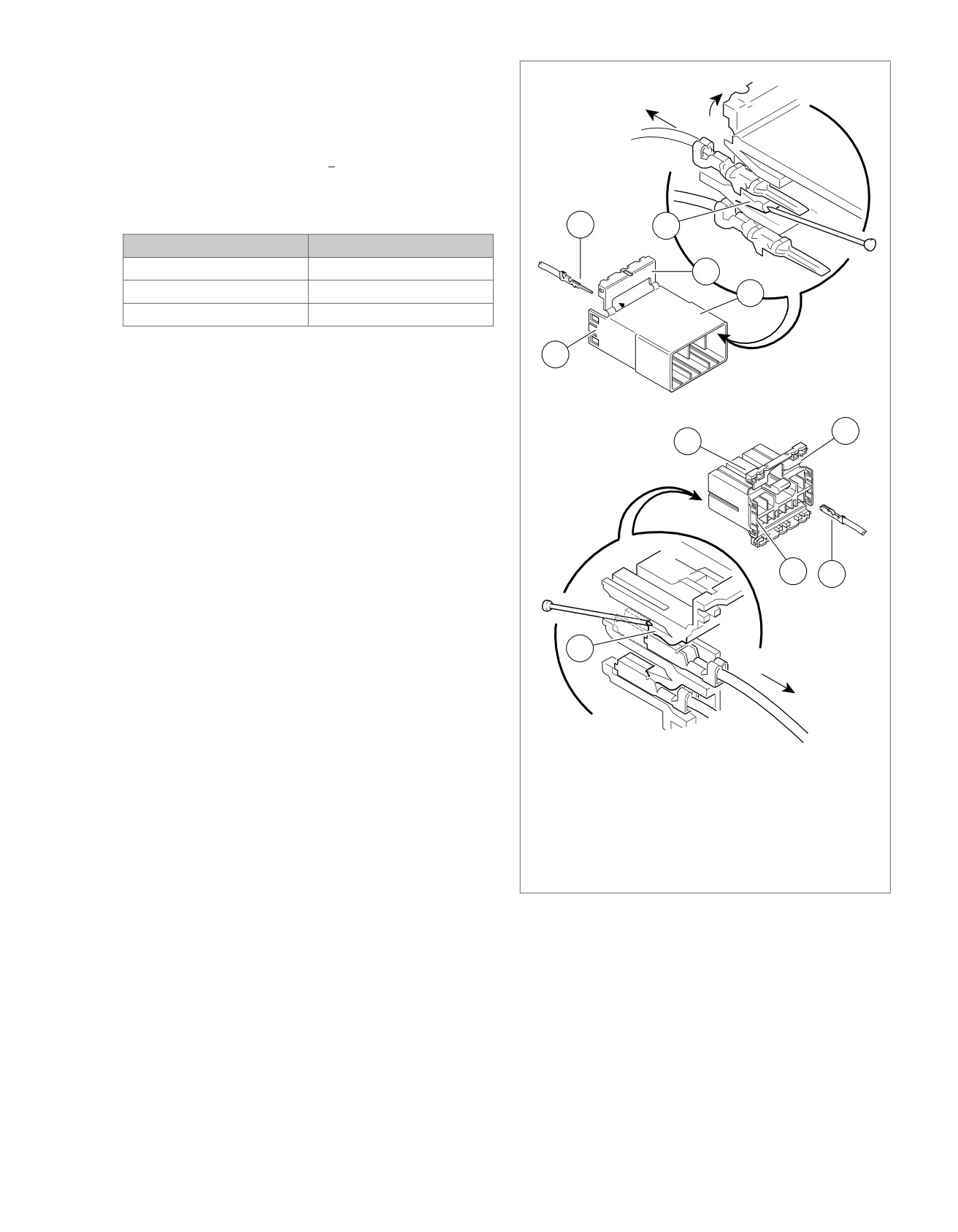
1. See Figure A-4. Bend back the latch (1) to free one end
in place.
of secondary lock (2) then repeat on the opposite end.
Hinge the secondary lock outward.
3. If OE location is a T-stud, fit large opening end of attach-
ment clip over T-stud and slide connector to engage T-
2. Look in the terminal side of the connector (opposite the
stud to small end of opening.
secondary lock) and note the cavity next to each terminal.
3. Insert a pick or pin into the terminal cavity until it stops.
NOTE
If socket/pin terminal tool is not available, a push pin/safety pin
or a Snap-on pick (Part No. TT600-3) may be used.
4. Press the tang in the housing to release the terminal.
a. Socket: Lift the socket tang (8) up.
b. Pin: Press the pin tang (7) down.
NOTE
A "click" is heard if the tang is released.
5. Gently tug on wire to pull wire and terminal from cavity.
2008 Touring Diagnostics: Appendix A Connector Repair A-3
HOME
NOTES
sm00013
•
Up and down can be determined by the position of the
release button, the button is the top of the connector.
•
On the pin side of the connector, tangs are positioned at
the bottom of each cavity, so the slot in the pin terminal
(on the side opposite the crimp tails) must face downward.
•
On the socket side, tangs are at the top of each cavity, so
the socket terminal slot (on the same side as the crimp
tails) must face upward.
5
7
2. Gently tug on wire end to verify that the terminal is locked
in place.
2
3. Rotate the hinged secondary lock inward until tabs fully
3
engage latches on both sides of connector.
sm00005
1
2
1
4
- AMP
1
2
3
1
6
2
8
- AMP
1
2
3
4
5
6
1
2
3
4
1. Latch
2. Secondary lock open
3. Pin housing
4. Socket housing
3
5. Pin terminal
6. Socket terminal
7. Tang (pin)
8. Tang (socket)
Figure A-4. AMP Multilock Connector: Socket and Pin
5
6
7
8
9
10
Housings
1.
3-place housing
Inserting Terminals into Housing
2.
6-place housing
3.
10-place housing
NOTE
Figure A-5. AMP Multilock Connector: Cavity Numbers on
See Figure A-5. Cavity numbers are stamped into the sec-
Secondary Locks (Socket Housings Shown)
ondary locks of both the socket and pin housings. Match the
wire color to the cavity number found on the wiring diagram.
1. Hold the terminal so the catch faces the tang in the
Preparing Wire Leads for Crimping
chamber. Insert the terminal into its numbered cavity until
1. Strip
5/32 in. (4.0 mm) of insulation from the wire lead.
it snaps in place.
A-4 2008 Touring Diagnostics: Appendix A Connector Repair
HOME
2. See Figure A-4 and Figure A-7. Select the pin/socket ter-
sm00013
minals from the parts catalog and identify the insulation
crimp tails (1) and the wire crimp tails (2) and the groove
for the crimp tool locking bar (3).
3. Identify the wire lead gauge and the corresponding crimper
tool and nesting die. Refer to Table A-1.
Table A-1. AMP Multilock Connector: Crimp Tool Wire
Gauge/Nest
5
7
WIRE GAUGE
NEST
20
Front
2
16
Middle
3
18
Rear
1
2
4
1
6
8
1. Latch
2. Secondary lock open
3. Pin housing
4. Socket housing
5. Pin terminal
6. Socket terminal
7. Tang (pin)
8. Tang (socket)
Figure A-6. AMP Multilock Connector: Socket and Pin
Housings
2008 Touring Diagnostics: Appendix A Connector Repair A-5
HOME
sm00001
sm00007
1
1
3
3
2
2
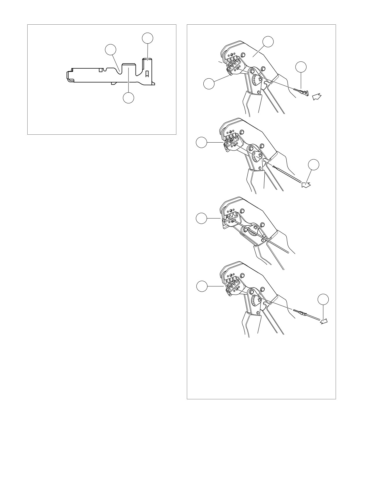
1. Insulation crimp tail
2. Wire crimp tail
3. Locking bar groove
Figure A-7. AMP Multilock Connector: Socket Terminal
4
Crimping Terminals to Leads
5
NOTE
Crimping with an Amp Multilock tool is a one step operation.
One squeeze crimps both the wire core and the insulation tails.
1. See Figure A-8. Squeeze the handles to cycle the AMP
MULTILOCK CRIMPER (Part No. HD-41609) to the fully
open position (1).
6
2. Raise locking bar by pushing up on bottom flange (2).
NOTE
See Figure A-4 and Figure A-7. Hold the terminal with the
insulation crimp tail (1) facing up. The tool will hold the terminal
by the locking bar groove (3) and crimp the wire crimp tail (2)
around the bare wire of the stripped lead and the insulation
crimp tail around the insulation.
3. See Figure A-8. With the insulation crimp tail facing
upward, insert terminal (pin or socket) (3) through the
7
locking bar, so that the closed side of the terminal rests
on the nest of the crimp tool.
8
4. Release locking bar to lock position of contact (4). When
correctly positioned, the locking bar fits snugly in the space
at the front of the core crimp tails.
5. Insert stripped end of lead (5) until ends make contact with
locking bar.
6. Verify that wire is positioned so that wire crimp tails
1.
Open position
squeeze bare wire strands, while insulation crimp tails fold
2.
Locking bar flange
over the wire lead insulation.
3.
Insert contact
4.
Release locking bar
7. Squeeze handle of crimp tool until tightly closed. Tool
5.
Insert lead
automatically opens when the crimping sequence is com-
6.
Squeeze
plete.
7.
Raise locking bar
8. Raise up locking bar (8) and remove crimped terminal.
8.
Remove crimped terminal
Figure A-8. AMP Multilock Connector: Terminal Crimping
Procedure
Inspecting Crimped Terminals
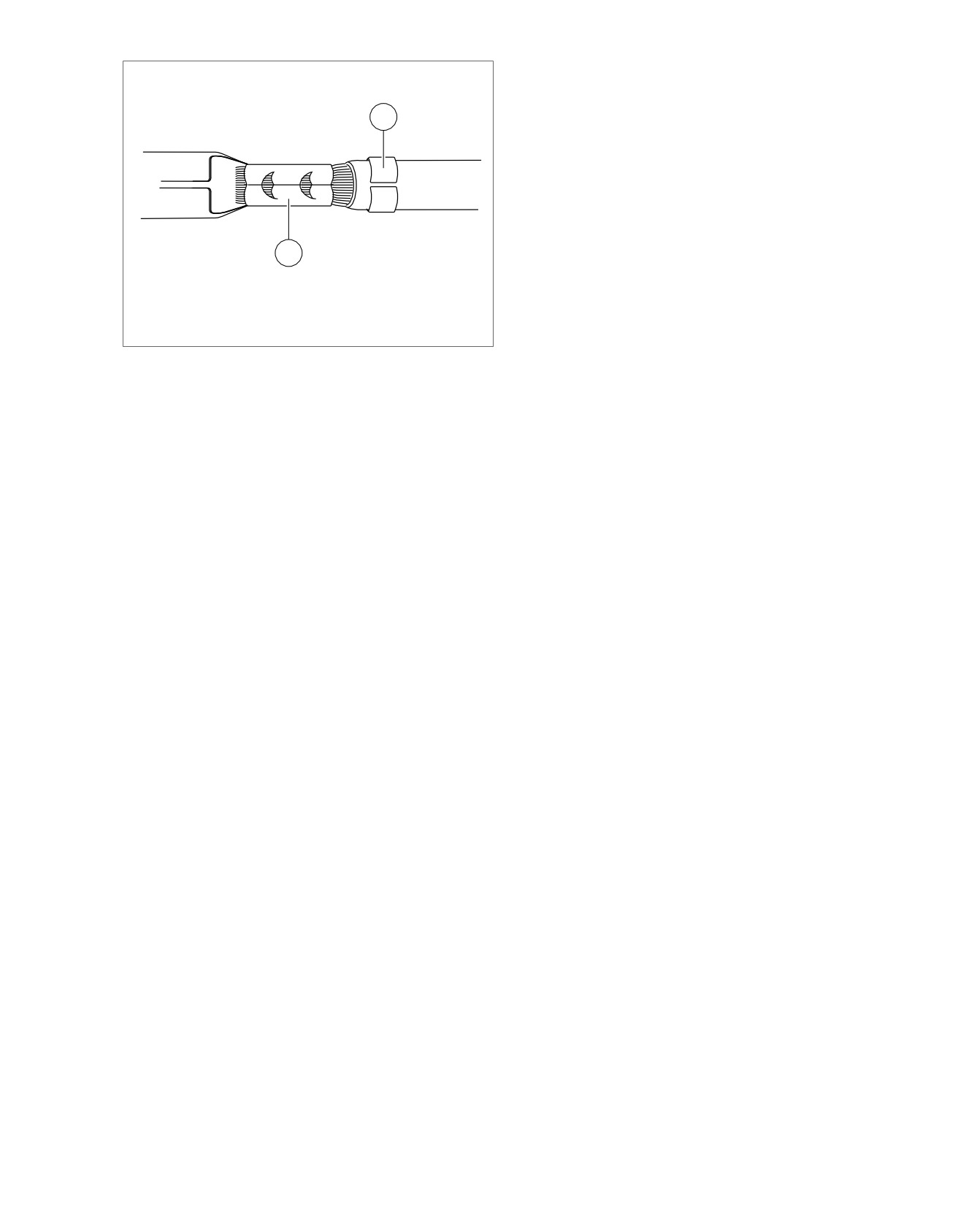
See Figure A-9. Inspect the wire core crimp (2) and insulation
crimp (1). Distortion should be minimal.
A-6 2008 Touring Diagnostics: Appendix A Connector Repair
HOME
sm00008
1
2
1. Insulation crimp
2. Wire core crimp
Figure A-9. AMP Multilock Connector: Terminal Crimp
2008 Touring Diagnostics: Appendix A Connector Repair A-7
HOME
DELPHI CONNECTORS
A.3
DELPHI CONNECTOR REPAIR
sm00014
General
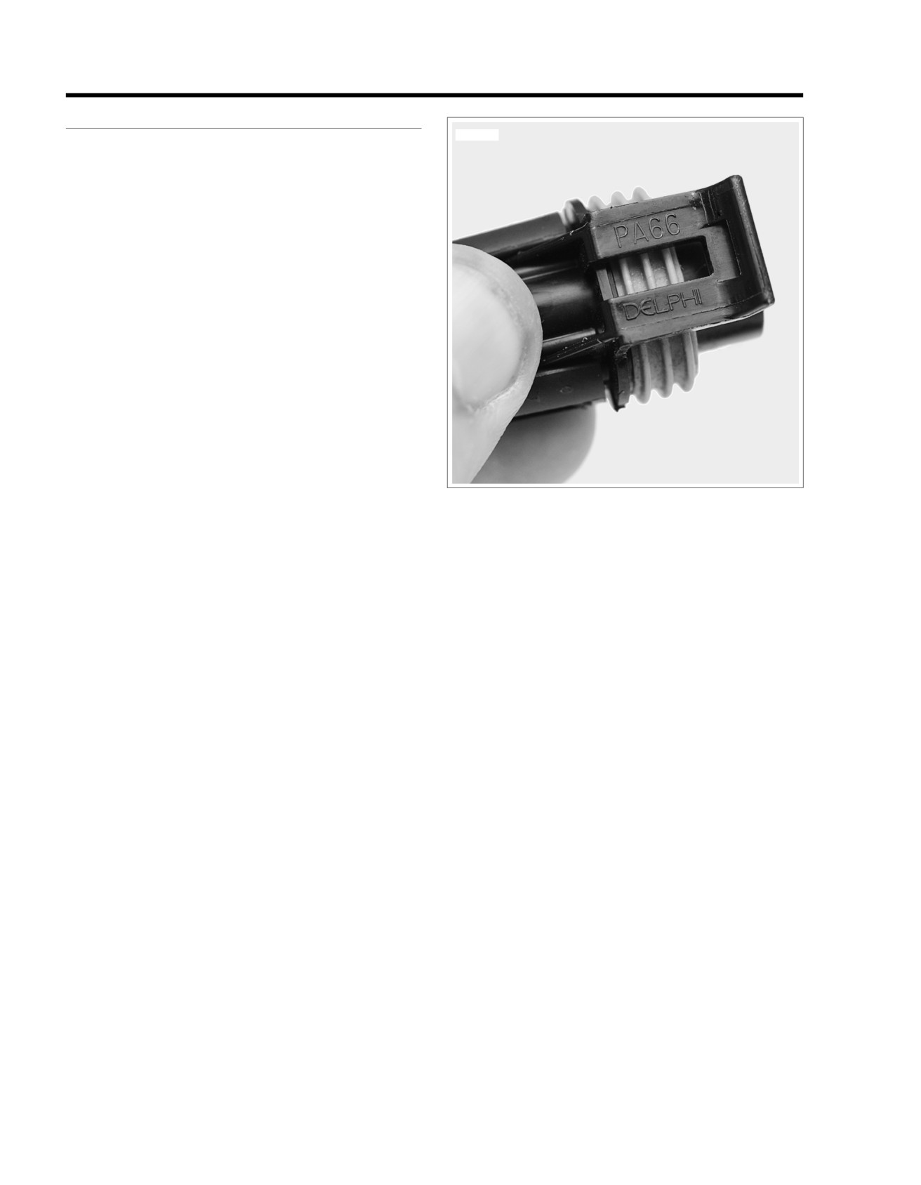
Delphi connectors are embossed with the brand name, Delphi,
on the housing latch.
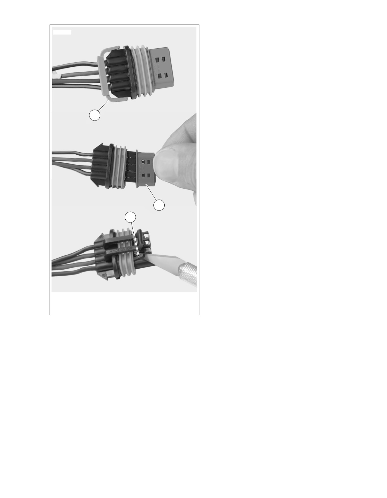
Separating Pin and Socket Housings
See Figure A-10. Bend back the external latch(es) slightly and
separate pin and socket halves of connector.
Mating Pin and Socket Housings
Push pin and socket halves of connector together until external
latch(es) engage.
Removing Socket Terminals
NOTE
Although the parts of the different Delphi connectors vary in
appearance, the instructions which follow will work for all. The
only exception is the oil pressure sender connector [139B], the
terminals of which are removed like the Packard push-to-seat
connectors. Therefore, see A.10 150 METRI-PACK CON-
NECTORS to remove/install terminals in this connector.
1. See Figure A-11. If present, free one side of wire lock (1)
Figure A-10. Delphi Connector: Socket Housing Latch
from ear on wire end of socket housing, then release the
other side. Release wires from channels in wire lock and
remove from socket housing.
2. Use a fingernail to pry colored terminal lock (2) loose and
then remove from mating end of socket housing.
3. Using a thin flat blade, like the unsharpened edge of a
hobby knife, gently pry tang (3) outward away from ter-
minal, and then tug on wire to back terminal out wire end
of chamber. Do not pull on wire until tang is released or
terminal will be difficult to remove.
Installing Socket Terminals
NOTE
For wire location purposes, alpha or numeric characters are
stamped into the wire end of each socket housing.
1. Gently push tang on socket housing inward toward
chamber. With the open side of the terminal facing the
tang, push terminal into chamber at wire end of socket
housing.
2. Gently tug on wire to verify that terminal is locked and will
not back out of chamber. If necessary, use fingernail to
push tang into engagement with terminal.
3. Install colored terminal lock onto mating end of socket
housing.
4. If present, seat wires in separate channels of wire lock
and then push channels inside chambers at wire end of
socket housing. Fully installed, slot on each side of wire
lock engages ear on socket housing.
A-8 2008 Touring Diagnostics: Appendix A Connector Repair
HOME
sm00015
1
2
3
1. Remove wire lock
2. Remove terminal lock
3. Pry tang outward
Figure A-11. Delphi Connector: Removing Socket
Terminals
2008 Touring Diagnostics: Appendix A Connector Repair A-9
HOME
DEUTSCH1-PLACE ELECTRICAL CONNECTORS
A.4
DEUTSCH 1-PLACE CONNECTOR REPAIR
sm00016
Separating Pin and Socket Housings
Depress external latch and separate the pin and socket hous-
ings of the Deutsch one place connector found on voltage
1
regulators.
Mating Pin and Socket Housings
Orient the housings so the latch faces the catch and push the
housings together until it clicks.
Removing Socket Terminals
NOTE
Rough handling or careless storage can result in tool damage.
Exercise care to avoid cracking or breaking the thin plastic
construction.
1. Pull rear wire seal from back of housing and slide down
voltage regulator cable to move out of the way.
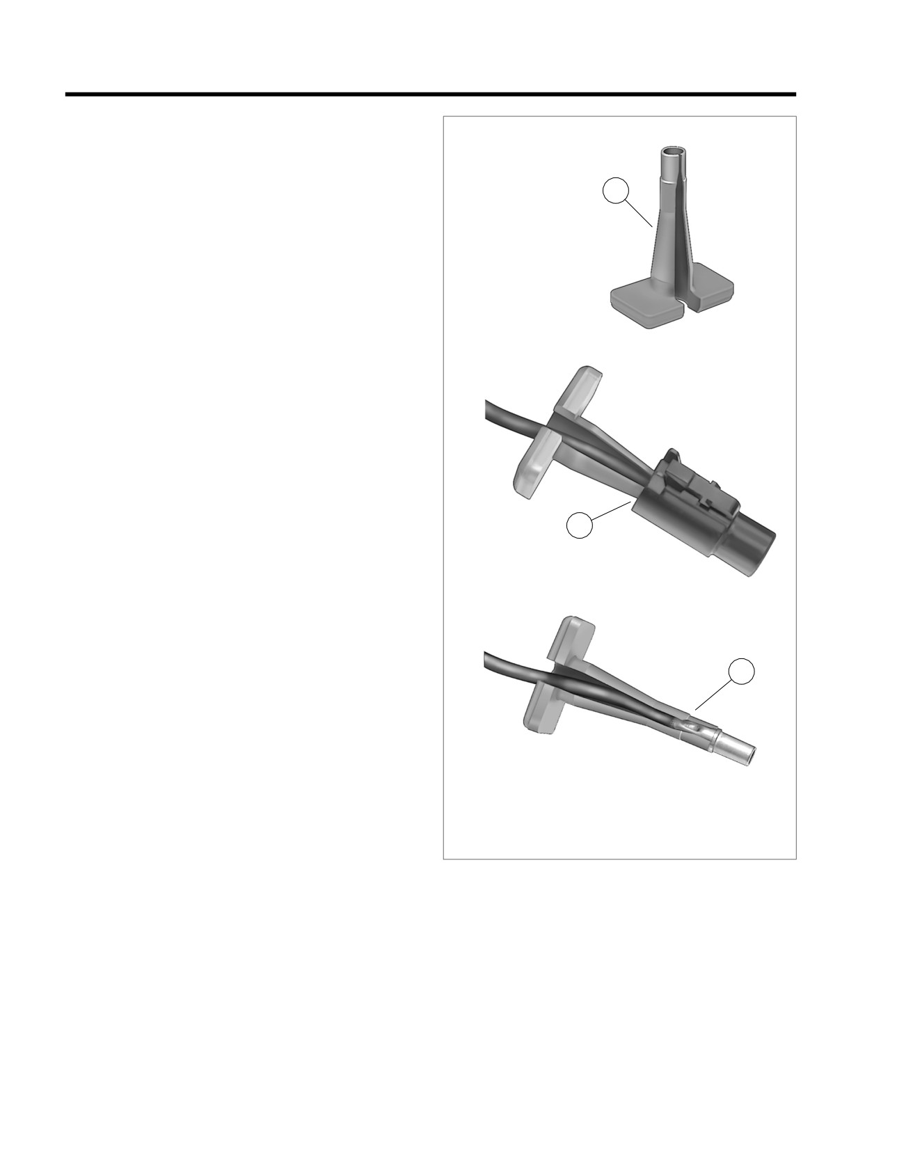
2. See Figure A-12. Using terminal pick tool (Deutsch®
114008) (1), install tool onto voltage regulator cable so
that the tapered end is in the wire end of the housing (2).
3. Push tool into wire end of housing until it bottoms. Gently
tug on housing to pull from terminal (3).
2
4. Remove tool from voltage regulator cable.
Installing Socket Terminals
1. Insert terminal into wire end of housing until it "clicks" in
place. Verify that terminal will not back out of housing. A
slight tug on the voltage regulator cable will confirm that
it is properly locked in place.
2. Fit rear wire seal into back of housing.
3
1. Deutsch terminal pick tool (114008)
2. Tool installed in housing
3. Terminal removed from housing
Figure A-12. Deutsch 1-Place Connector: Remove
Socket/Pin Housing
A-10 2008 Touring Diagnostics: Appendix A Connector Repair
HOME
DEUSCH ELECTRICAL CONNECTORS
A.5
4. Place large end of slot on attachment clip over T-stud on
DEUTSCH CONNECTOR REPAIR
frame. Push assembly forward to engage small end of
PART NUMBER
TOOL NAME
slot.
HD-41475
DEUTSCH CONNECTOR SERVICE
KIT
sm00017
HD-41475-100
FLAT BLADE L-HOOK
General
3
Deutsch connectors are colored coded for location purposes.
Those connectors associated with left side accessories, such
as the front and rear left turn signals, are gray. All other con-
nectors, including those associated with right side accessories,
are black.
1
NOTE
A DEUTSCH CONNECTOR SERVICE KIT (Part No. HD-
41475) contains a selection of wire seals, internal seals, seal
plugs, secondary locking wedges, attachment clips and
socket/pin terminals. Also included is a compartmented storage
box, carrying case and a FLAT BLADE L-HOOK (Part No. HD-
2
41475-100) is used for the removal of all types of locking
1
wedges.
Separating Pin and Socket Housings
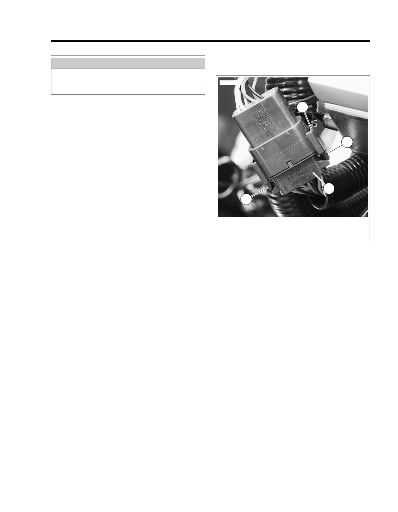
See Figure A-12. To separate the connector halves, depress
1. External latch
the external latch(es) (1) on the socket housing (2) while
2. Socket housing
rocking the pin (3) and socket housings.
3. Pin housing
NOTES
Figure A-13. Deutsch Connector
•
Generally, the socket housing is found on the accessory
side, while the pin housing is plumbed to the wiring har-
Removing Socket Terminals
ness.
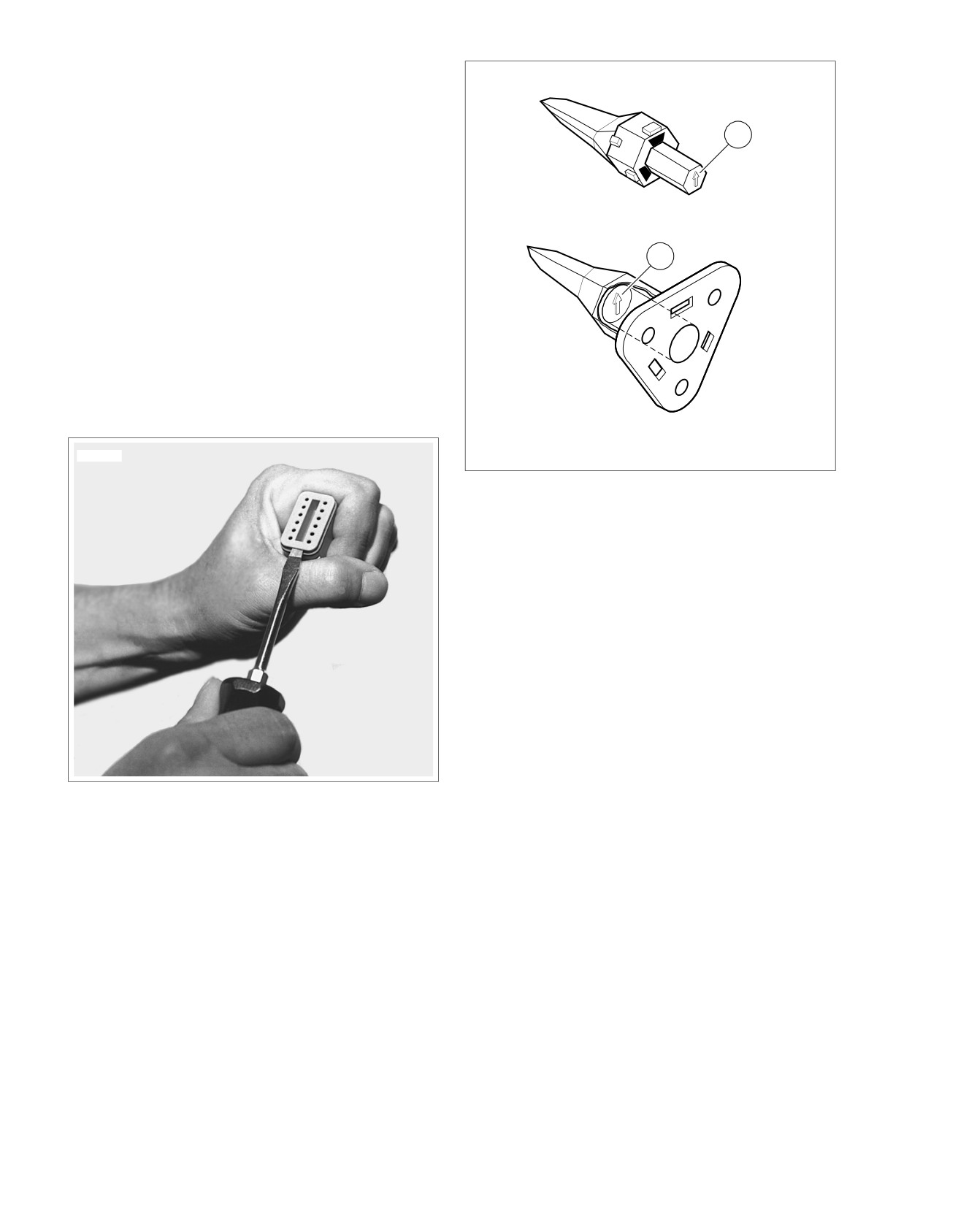
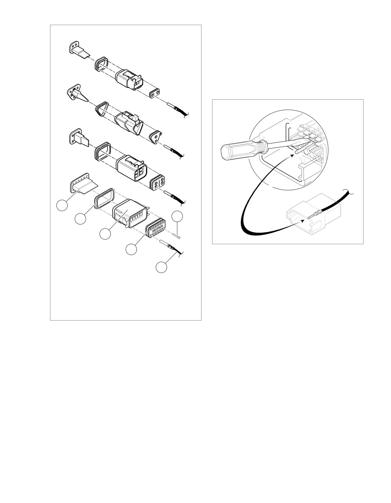
1. See Figure A-14. Insert a small screwdriver between the
•
Two-, three-, four- and six-place Deutsch connectors have
socket housing and locking wedge in-line with the groove
one latch on the connector.
(in-line with the pin holes if the groove is absent). Turn the
•
Eight- and twelve-place connectors have a latch on each
screwdriver 90 degrees to pop the wedge up and remove
side. Simultaneously press both latches to separate the
the secondary locking wedge.
connector.
2. See Figure A-17. Use a pick or small screwdriver to
Mating Pin and Socket Housings
depress terminal latches inside socket housing and back
out sockets through holes in rear wire seal.
1. Align the connectors to match the wire lead colors.
a. For One External Latch: Two-, three-, four- and six-
NOTE
place Deutsch connectors have one external latch on
If wire leads require new terminals, see the instructions for
the socket half of the connector. To fit the halves of
crimping terminals.
the connector together, the latch on the socket side
must be aligned with the latch cover on the pin side.
Installing Socket Terminals
b. For Two External Latches: (8-place and 12-place)
1. Match wire lead color to connector cavity.
Align the tabs on the socket housing with the grooves
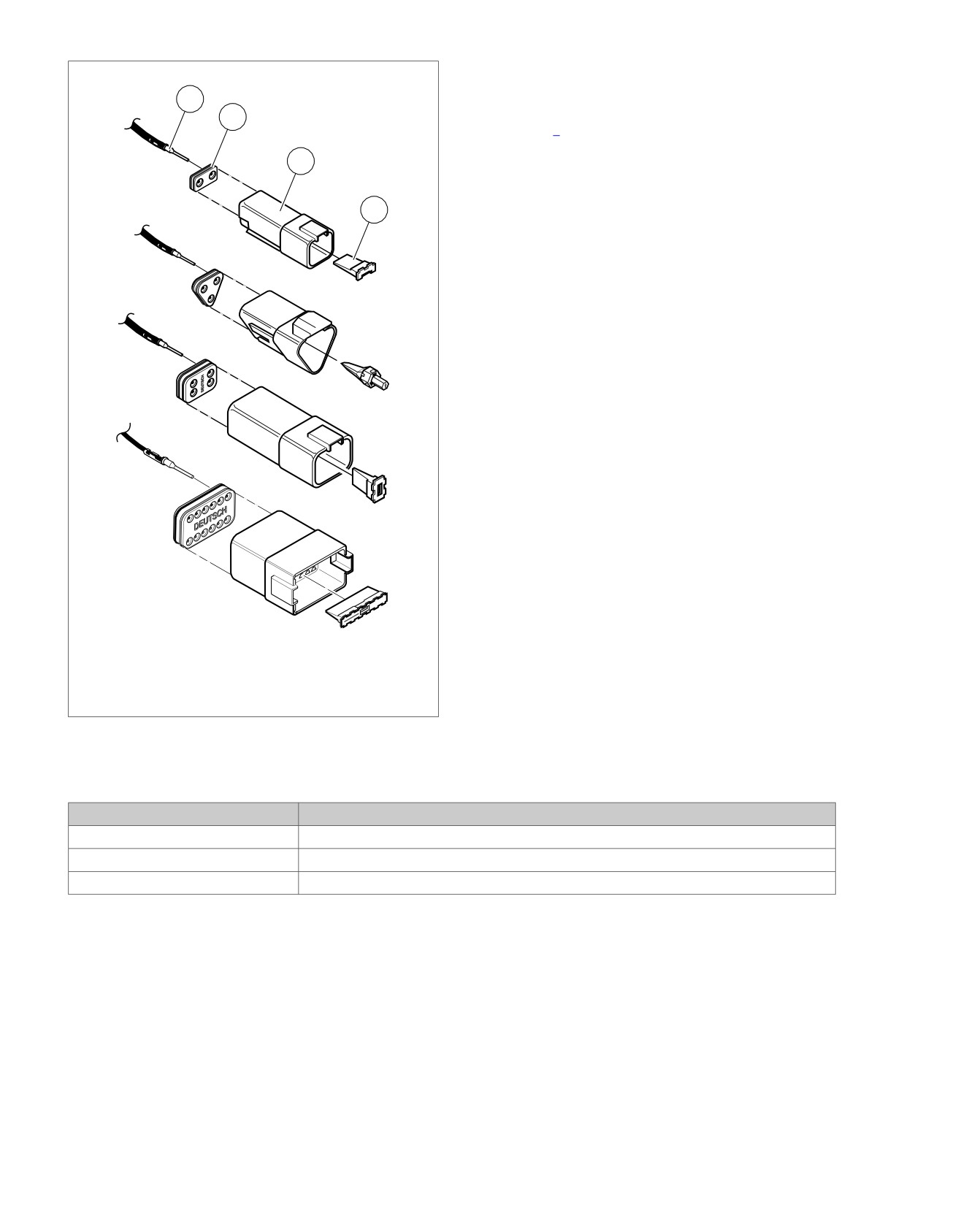
2. See Figure A-16. Fit rear wire seal (1) into back of socket
on the pin housing.
housing (2), if removed.
2. Insert socket housing into pin housing until it snaps or
3. Grasp wire lead (3) approximately
1.0 in. (25.4 mm)
clicks into place.
behind the socket terminal. Gently push socket through
For Two External Latches: (8-place and 12-place) If
hole in wire seal into its chambers until it "clicks" in place.
latches do not click (latch), press on one side of the con-
4. A tug on the wire will confirm that it is properly locked in
nector until that latch engages, then press on the opposite
place.
side to engage the other latch.
3. If necessary, fit the attachment clip to the pin housing.
2008 Touring Diagnostics: Appendix A Connector Repair A-11
HOME
NOTE
sm00018
Seal plugs (6) are installed through the wire seals of unused
chambers. If removed, seal plugs must be replaced to seal the
connector.
2
5. Install internal seal (4) on lip of socket housing, if removed.
6. Insert tapered end of secondary locking wedge (5) into
socket housing and press down until it snaps in place. The
wedge fits into the center groove within the socket housing
and holds the terminal latches tightly closed.
NOTES
1
•
See Figure A-15. While rectangular wedges do not require
a special orientation, the conical secondary locking wedge
of the 3-place connector must be installed with the arrow
(1) pointing toward the external latch.
•
If the secondary locking wedge does not slide into the
installed position easily, verify that all terminals are fully
installed in the socket housing. The lock indicates when
terminals are not properly installed by not entering its fully
installed position.
1. Arrow on socket locking wedge
sm00009
2. Arrow on pin locking wedge
Figure A-15. Deutsch Connector: 3-Place Locking Wedges
Figure A-14. Deutsch Connector: Remove Secondary
Locking Wedge
A-12 2008 Touring Diagnostics: Appendix A Connector Repair
HOME
ation of the alignment tabs differ between the black and
sm00010
gray connectors, plugs or receptacles must be replaced
by those of the same color.
•
When replacing both socket and pin housings, then the
black may be substituted for the gray, and vice versa. The
socket and pin housings of all other connectors are inter-
changeable, that is, the black may be mated with the gray,
since the alignment tabs are absent and the orientation
of the external latch is the same.
sm00019
5
6
4
2
1
Figure A-17. Deutsch Connector: Depress Terminal Latch
and Back Out Pin
3
Installing Pin Terminals
1. Wire seal
2. Socket housing
1. See Figure A-18. Fit wire seal (1) into back of pin housing
3. Wire lead
(2).
4. Internal seal
2. Grasp wire lead approximately 1.0 in. (25.4 mm) behind
5. Secondary locking wedge
the pin terminal (3). Gently push pin through holes in wire
6. Seal plug
seal into its respective numbered chamber until it "clicks"
Figure A-16. Deutsch Connector: 2, 3, 4 and 12-Place
in place.
Socket Housings
NOTE
A tug on the wire lead will confirm that a pin is locked in place.
Removing Pin Terminals
3. Insert tapered end of secondary locking wedge (4) into
pin housing and press down until it snaps in place.
1. Use the hooked end of a stiff piece of mechanics wire, a
needle nose pliers or the FLAT BLADE L-HOOK (Part
NOTES
No. HD-41475-100) to remove the secondary locking
•
The wedge fits in the center groove of the pin housing and
wedge.
holds the terminal latches tightly closed.
2. Gently depress terminal latches inside pin housing and
•
See Figure A-15. While rectangular wedges do not require
back out pins through holes in wire seal.
a special orientation, the conical secondary locking wedge
of the 3-place connector must be installed with the arrow
NOTES
(2) pointing toward the external latch.
•
If wire leads require new terminals, see the instructions
for crimping terminals.
•
If the secondary locking wedge does not slide into the
installed position easily, verify that all terminals are fully
•
If it should become necessary to replace a pin or socket
installed in the pin housing. The lock indicates when ter-
housing, please note that the 8-place and 12-place gray
minals are not properly installed by not entering its fully
and black connectors are not interchangeable. Since loc-
installed position.
2008 Touring Diagnostics: Appendix A Connector Repair A-13
HOME
Crimping Terminals
sm00020
3
Identify which of the types of Deutsch terminals are used with
the connector and follow the corresponding crimping instruc-
1
tions. Refer to Table A-2.
2
4
1. Wire seal
2. Pin housing
3. Pin terminal
4. Locking wedge
Figure A-18. Deutsch Connector: 2, 3, 4 and 12-Place Pin
Housings
Table A-2. Deutsch Connector: Terminal Crimping Instructions
TYPE
CRIMPING INSTRUCTIONS
Standard (with crimp tails)
A.6 DEUTSCH STANDARD TERMINALS
Mini
Terminal (solid barrel)
A.8 DEUTSCH SOLID BARREL TERMINALS
Mini
Terminal (with crimp tails)
A.7 DEUTSCH MINI-TERMINAL CRIMPS
A-14 2008 Touring Diagnostics: Appendix A Connector Repair
HOME
DEUTSCH STANDARD TERMINALS
A.6
straight upward. When positioned, the locking bar fits snugly
DEUTSCH STANDARD TERMINAL CRIMPS
in the space between the contact band and the core crimp tails.
PART NUMBER
TOOL NAME
4. Insert stripped wire core between crimp tails until ends
HD-39965-A
DEUTSCH TERMINAL CRIMP TOOL
make contact with locking bar. Verify that wire is positioned
so that short pair of crimp tails squeeze bare wire strands,
Preparing Wire Leads for Crimping
while long pair folds over the insulation.
1. Use a shop gauge to determine gauge of wire lead.
5. Squeeze handle of crimp tool until tightly closed. Tool
2. Strip lead removing 5/32 in. (4.0 mm) of insulation.
automatically opens after the terminal is crimped.
6. Raise locking bar up and remove wire lead and terminal.
Crimping Terminal to Lead
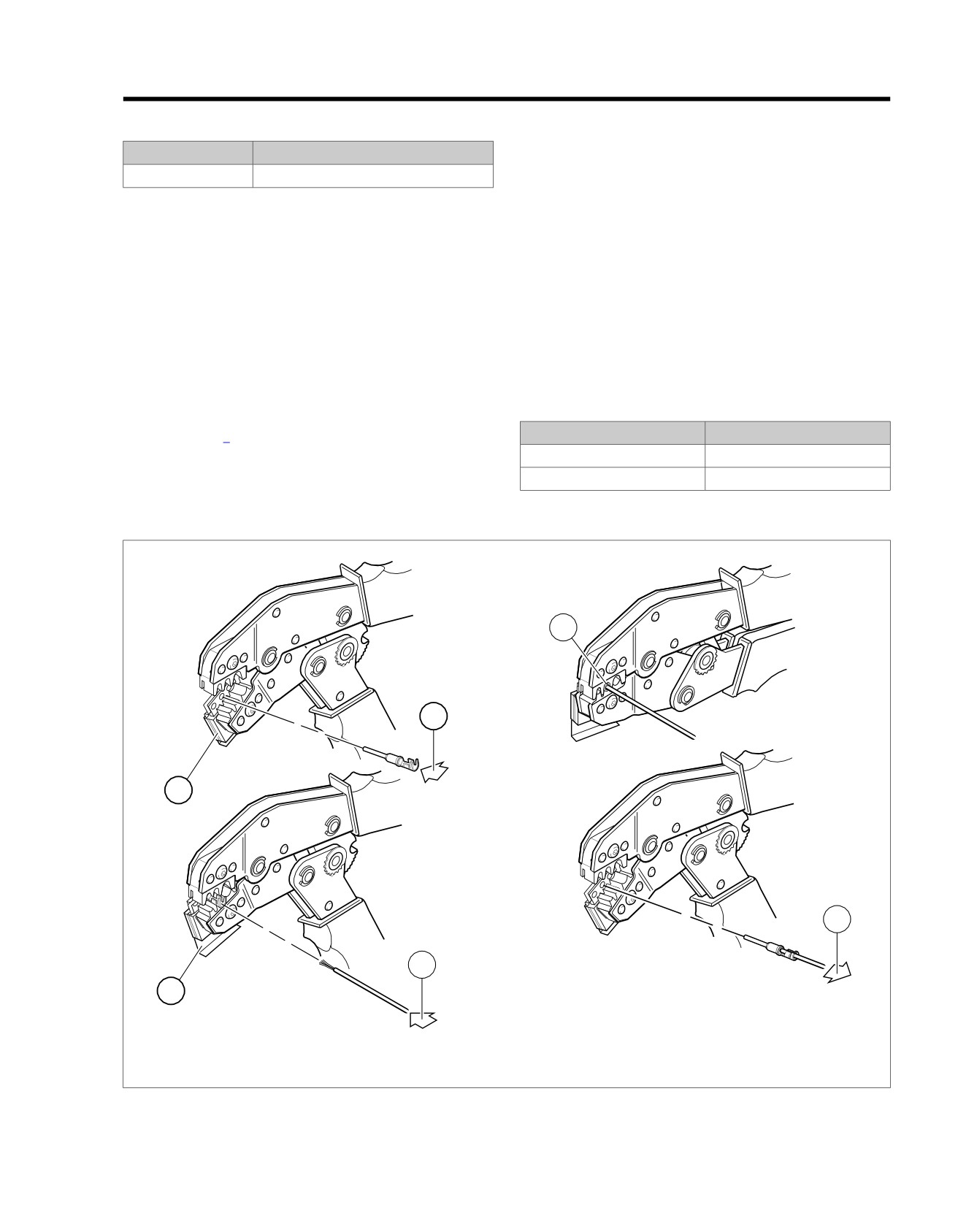
1. See Figure A-19. Squeeze the handles of the DEUTSCH
Inspecting Crimps
TERMINAL CRIMP TOOL (Part No. HD-39965-A) to open
Inspect the wire core and insulation crimps. Distortion should
the jaws. Push the locking bar (1) up.
be minimal.
2. Insert (2) terminal (socket/pin) through hole of the locking
bar, so that the rounded side of the contact barrel rests in
Table A-3. Deutsch Standard Terminal Crimp: Wire Gauge
the nest (concave split level area) with the crimp tails
To Die
facing upward. To match the wire gauge to the crimp tool
WIRE GAUGE (AWG)
CRIMP TOOL DIE
die, refer to Table A-3.
20
Front
3. Release locking bar to lock terminal in die.
16-18
Middle
NOTE
If the crimp tails are slightly out of vertical alignment, the crimp
tool automatically rotates the terminal so that the tails face
sm00021
5
2
1
6
4
3
1. Open jaws and raise locking bar
4. Insert stripped lead
2. Insert terminal in locking bar
5. Squeeze crimper
3. Release locking bar to lock terminal in die
6. Raise locking bar and remove terminal
Figure A-19. Crimping a Deutsch Standard Terminal
2008 Touring Diagnostics: Appendix A Connector Repair A-15
HOME
DEUTSCH MINI-TERMINAL CRIMPS
A.7
DEUTSCH MINI TERMINAL CRIMPS
Inspecting Crimps
Inspect the core and insulation crimps. Distortion should be
PART NUMBER
TOOL NAME
minimal.
HD-38125-7
PACKARD TERMINAL CRIMPER
Preparing Wire Leads for Crimping
sm00022
Strip wire lead removing 5/32 in. (4.0 mm) of insulation.
Crimping a Mini Terminal to Wire Lead
1
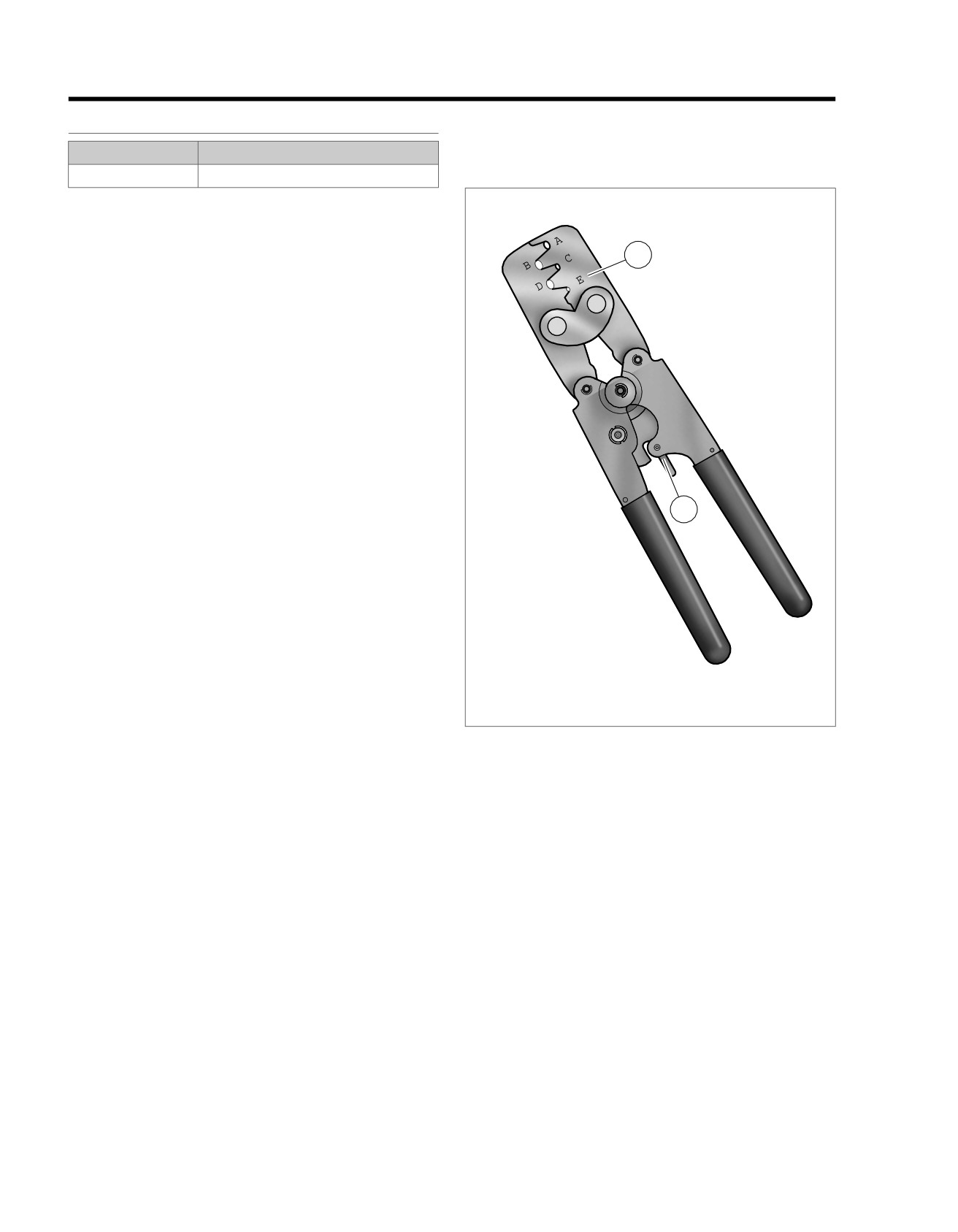
1. See Figure A-20. Compress the handles of PACKARD
TERMINAL CRIMPER (Part No. HD-38125-7) until the
ratchet (2) automatically opens.
NOTE
Always perform core crimp before insulation crimp.
2. Position the core crimp on die E (1) of the crimper. Be
sure the core crimp tails are facing the forming jaws.
3. Gently apply pressure to handles of tool until crimpers just
secure the core crimp tails.
4. Insert stripped wire core stands between crimp tails. Pos-
ition wire so that short pair of crimp tails squeeze bare
wire strands, while long pair squeeze over the insulation.
2
5. Squeeze handle of crimper until tightly closed. Tool auto-
matically opens when the crimping sequence is complete.
NOTE
If the crimper does not open, it can be opened by squeezing
the ratchet trigger (2).
6. Position the insulation crimp on nest C of the crimper. Be
sure the insulation crimp tails are facing the forming jaws.
7. Squeeze handle of crimp tool until tightly closed. Tool
automatically opens when the crimping sequence is com-
1.
E die
plete.
2.
Crimper ratchet trigger
Figure A-20. Packard Terminal Crimper (HD-38125-7)
A-16 2008 Touring Diagnostics: Appendix A Connector Repair
HOME
DEUTSCH SOLID BARREL
TERMINALS
A.8
DEUTSCH SOLID BARREL TERMINAL
sm00023
CRIMPS
5
PART NUMBER
TOOL NAME
HD-42879
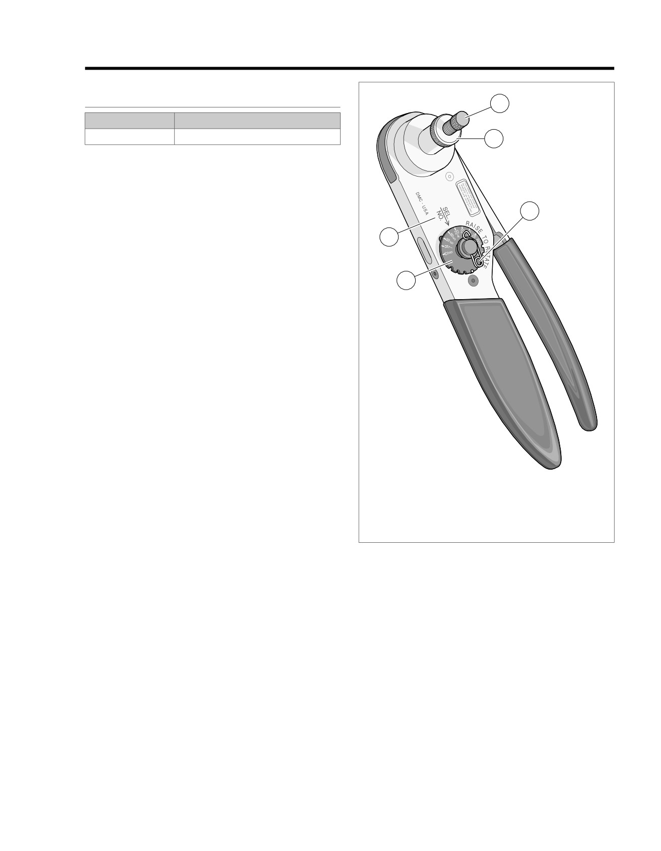
ELECTRICAL CRIMPER TOOL
4
Preparing Wire Leads For Crimping
For size 20, 16 and 12 contacts, wire ranges 26-12 AWG.
Strip wire lead removing 1/4 in. (6.4 mm) of insulation.
Adjusting Crimper Tool
1
1. See Figure A-21. Squeeze the ELECTRICAL CRIMPER
TOOL (Part No. HD-42879) handles to cycle the crimp
3
tool to open.
2. Remove locking pin (1) from selector knob (2).
2
3. Raise selector knob and rotate until selected wire size
stamped on wheel is aligned with "SEL. NO." arrow (3).
4. Loosen knurled locknut (4) and turn adjusting screw (5)
clockwise (in) until it stops.
Crimping a Barrel Contact To Wire Lead
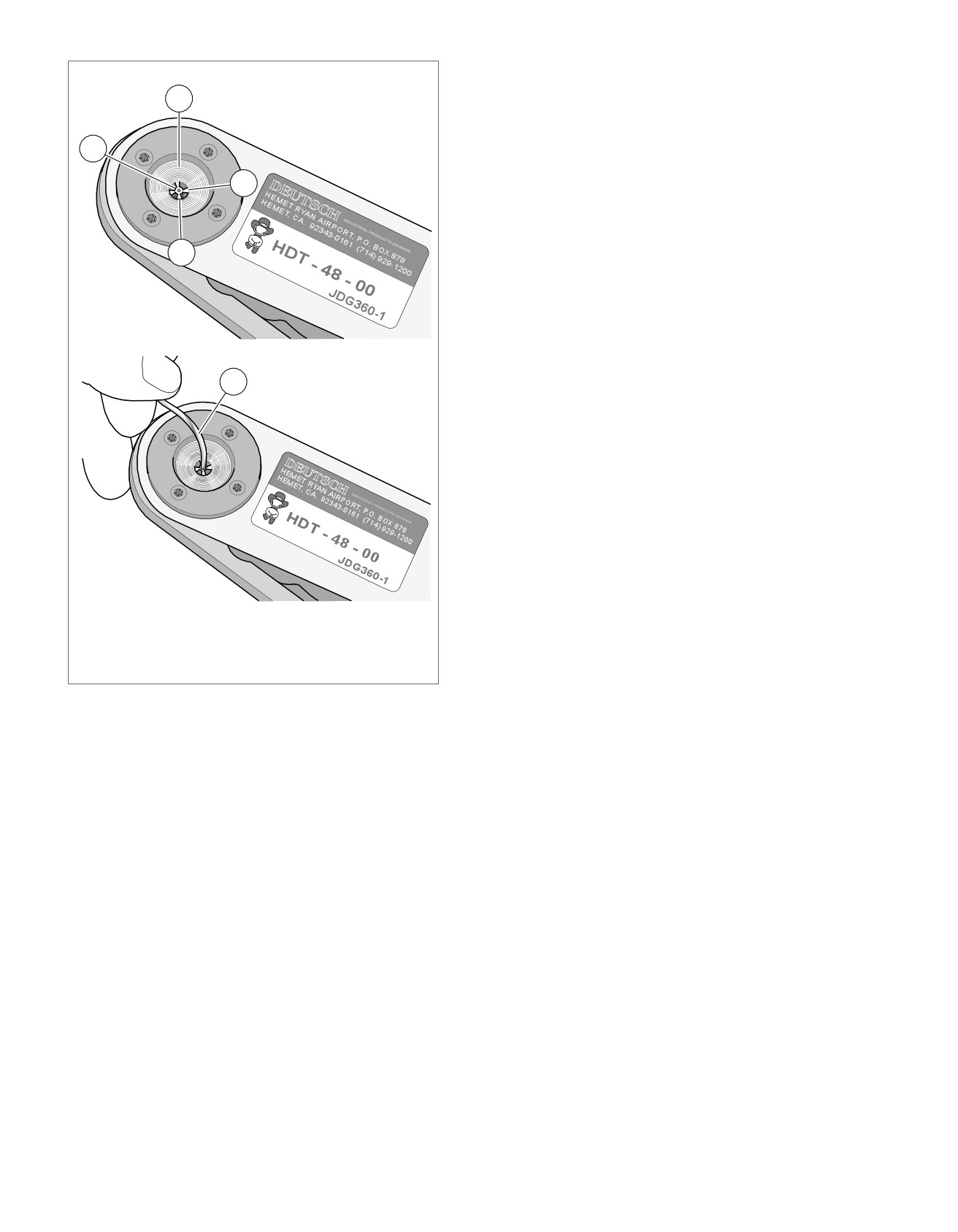
1. See Figure A-22. Turn tool over and drop contact barrel
(1) into indentor cover (2) hole with the wire end out.
2. Turn adjusting screw counterclockwise (out) until contact
is flush with bottom of depression in indentor cover.
Tighten knurled locknut.
3. Slowly squeeze handles of crimp tool until contact is
centered between the four indentor points (3).
4. Insert bare wire core strands of stripped wire lead (4) into
contact barrel. Squeeze handle of crimp tool until tightly
closed. Tool automatically opens when the crimping
1.
Locking pin
sequence is complete.
2.
Selector knob
3.
SEL. NO. arrow
5. Remove wire lead with crimped contact from indentor.
4.
Knurled locknut
NOTE
5.
Adjusting screw
Tool must be readjusted when changing contact size/type.
Figure A-21. Electrical Crimper Tool (HD-42879)
6. Install pin to lock selector knob.
Inspecting Crimps
Inspect the crimp. All core wire strands are to be crimped in
the barrel.
2008 Touring Diagnostics: Appendix A Connector Repair A-17
HOME
sm00024
2
1
3
3
4
1. Contact barrel
2. Indentor cover
3. Indentor point
4. Stripped wire lead
Figure A-22. Deutsch Solid Barrel
A-18 2008 Touring Diagnostics: Appendix A Connector Repair