Harley Davidson 2008 Touring Models. Electrical Diagnostics Manual - page 31

HOME
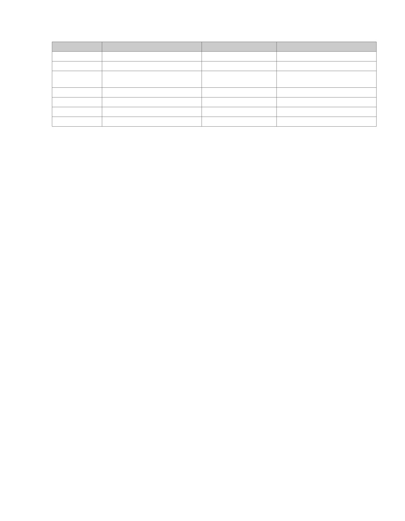
Table 6-15. FLHX, FLHT/C/U Connector Locations
NO.
DESCRIPTION
MODEL
TYPE
LOCATION
[1]
Main to interconnect har-
ALL
16-place Molex (black)
Inner fairing - right radio support bracket
ness
[5]
MAXIFUSE
ALL
2-place Packard
Under left side cover
[7]
Rear fender lights harness
ALL
8-place Multilock
Top of rear fender (under seat)
[20]
Console harness
ALL
16-place Molex
Under seat
[22]
Interconnect
to
right
ALL
12-place Molex (black)
Inner fairing - right fairing support brace
handlebar switches
[33]
Ignition switch
ALL
3-place Packard
Inner fairing - under radio (front of Ignition
Switch housing)
[39]
Speedometer
FLHT/C/U
12-place Packard
Inner fairing (back of speedometer)
FL
TR
12-place Packard
Under bezel (back of speedometer)
[64-1]
Fuse block
ALL
Packard
Under left side cover
[64-2]
Fuse block
ALL
Packard
Under left side cover
[77]
Voltage regulator
ALL
2-place Lyall
Bottom of voltage regulator (right side)
[93]
T
ail lamp
ALL
4-place Multilock
Circuit board under tail lamp assembly
[94]
Rear
fender light harness to
ALL
6-place Multilock
Circuit board under tail lamp assembly
circuit board
[108]
T
achometer
ALL
12-place Packard
Inner fairing (back of tachometer)
[121-1]
Rear brake light switch
ALL
Spade terminals
Bottom of rear frame downtube (right side)
[121-2]
Rear brake light switch
ALL
Spade terminals
Bottom of rear frame downtube (right side)
[166]
ABS module
ALL
20-place Molex
Under right side cover
[167]
Front wheel speed sensor
ALL
2-place Packard
Below fuel tank (left side)
[168]
Rear wheel speed sensor
FLHX/FLHT/
2-place Packard
Fairing
FLTR
FLHR
Inside headlamp nacelle
[201]
ABS diode pack
ALL
4-place Deutsch
Under left side cover
[222]
Main to ignition harness
ALL
4-place Packard
Rear of fuel tank
2008 Touring Diagnostics: ABS 6-61
HOME
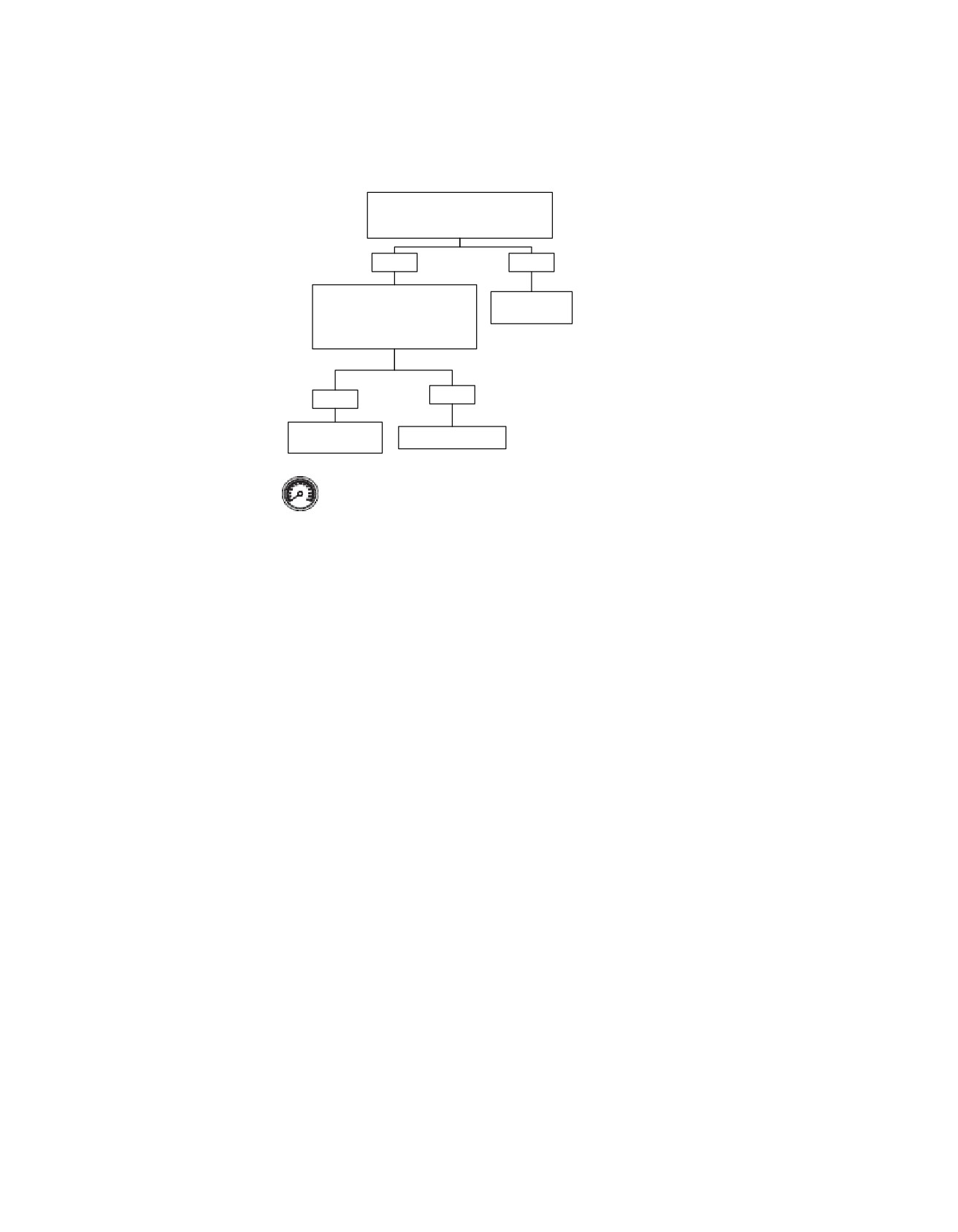
Calibration Programming Required: DTC C1158
Clear the DTC. Operate the ABS under
the conditions for running the DTC.
Does the DTC reset?
YES
NO
Using Digital Technician (See your
Refer to
dealer) attempt to calibrate the
Diagnostic Tips.
ECU. Clear the DTC.
Does the DTC reset?
NO
YES
Replace ABS
Calibration complete.
Module.
Clear DTCs using speedometer self diagnostics.
See 2.3 SPEEDOMETER SELF DIAGNOSTICS.
Confirm proper operation with no check engine lamp.
fc01574_en
6-62 2008 Touring Diagnostics: ABS
HOME
DTC C1212
6.20
DTC C1212: FRONT OR REAR BRAKE NOT
Action Taken When the DTC Sets
APPLIED WITH DECEL
No action is taken when this code is set. The ABS indicator
DOES NOT illuminate and the ABS is still active.
PART NUMBER
TOOL NAME
Conditions for Clearing the DTC
HD-41404-B
HARNESS CONNECTOR TEST KIT
The condition for the DTC is no longer present and the DTC
Circuit Description
has been cleared with either a "WOW" test or Digital Techni-
The ABS module monitors the front and rear brake switch
cian.
inputs through terminal "13" and terminal "3". This allows the
The ECU automatically clears the historic DTC when a current
ABS to determine if the brake is being applied or not when a
DTC is not detected in 50 consecutive drive cycles.
wheel is decelerating.
Diagnostic Tips
Conditions for Running the DTC
The following conditions are possible causes for this fault:
•
Ignition voltage is greater than 6.5V.
•
A short or open on the brake switch input circuits to the
Conditions for Setting the DTC
ABS module.
The DTC will set if the following conditions exist. The first four
•
Downshifting up a steep hill without using the brakes
conditions have to occur twice.
consecutive times could cause this code.
•
The front or rear brake is not applied.
Diagnostic Notes
•
There is no current ABS event in progress.
Each reference number below correlates to a circled number
on the flow chart(s).
•
Vehicle speed exceeds 15 MPH (24 km/h).
1. Use HARNESS CONNECTOR TEST KIT (Part No. HD-
•
Vehicle decelerates at a rate greater than 5 MPH (8 km/h)
41404-B) with gray male probes and patch cords.
per second for more than two seconds.
•
Vehicle speed drops below 15 MPH (24 km/h).
2008 Touring Diagnostics: ABS 6-63
HOME
1C
Front Stop
em00157
[64-1]
ACCY
Lamp
Fuse
Switch
15 Amp
1D
[166B]
[166A]
ABS Module
1
2
[22A]
See appendix B
1
2
[22B]
main harness
page 1 of 3
PK/BN
[121-2B]
1
1
[121-1B]
O/W
5
5
O/W
[121-2A]
1
1
[121-1A]
Rear
[1B]
[1A]
Stop
R/BN
13
13
Front brake input
Pressure
Lamp
(Except FLHR)
Switch
Switch
Electronic
PK/BN
3
3
Rear brake input
Control
Module (ECM)
[78A] [78B]
Brake switch input
25
25
R/BE
4
3
2
1
[201B]
ABS
4
3
2
1
[201A]
Diode
Pack
Circuit Board
R/Y
6
6
R/Y
R/Y
4
4
3
3
R/Y
BK
5
5
BK
BK
6
6
4
4
BK
Brake Relay
O/V
3A
87
5
Tail/Stop
[7A] [7B]
[94B] [94A]
[93A] [93B]
R/Y
2B
30
3
See appendix B
Lamp
R/BE
2A
85
2
main harness
BK
3B
86
1
page 1 of 3
[64-2]
[GND 1A]
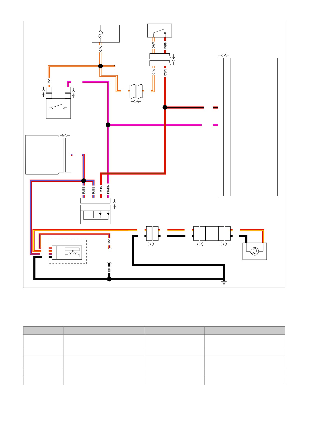
Figure 6-30. Brake Switches Schematic
Table 6-16. FLHX, FLHT/C/U Connector Locations
NO.
DESCRIPTION
TYPE
LOCATION
[1]
Main to interconnect harness
16-place Molex (black)
Inner fairing
- right radio support
bracket
[7]
Rear fender lights harness
8-place Multilock
Top of rear fender (under seat)
[22]
Interconnect to right handlebar
12-place Molex (black)
Inner fairing - right fairing support brace
switches
[64-1]
Fuse block
Packard
Under left side cover
[64-2]
Fuse block
Packard
Under left side cover
6-64 2008 Touring Diagnostics: ABS
HOME
Table 6-16. FLHX, FLHT/C/U Connector Locations
NO.
DESCRIPTION
TYPE
LOCATION
[78]
Electronic Control Module (ECM)
73-place Delphi
Under seat
[93]
T
ail lamp
4-place Multilock
Circuit board under tail lamp assembly
[94]
Rear fender light harness to circuit
6-place Multilock
Circuit board under tail lamp assembly
board
[121-1]
Rear brake switch
Spade terminals
Lower right side behind exhaust
[121-2]
Rear brake switch
Spade terminals
Lower right side behind exhaust
[166]
ABS module
20-place
Behind right side cover
[201]
ABS diode pack
4-place
Behind left side cover
2008 Touring Diagnostics: ABS 6-65
HOME
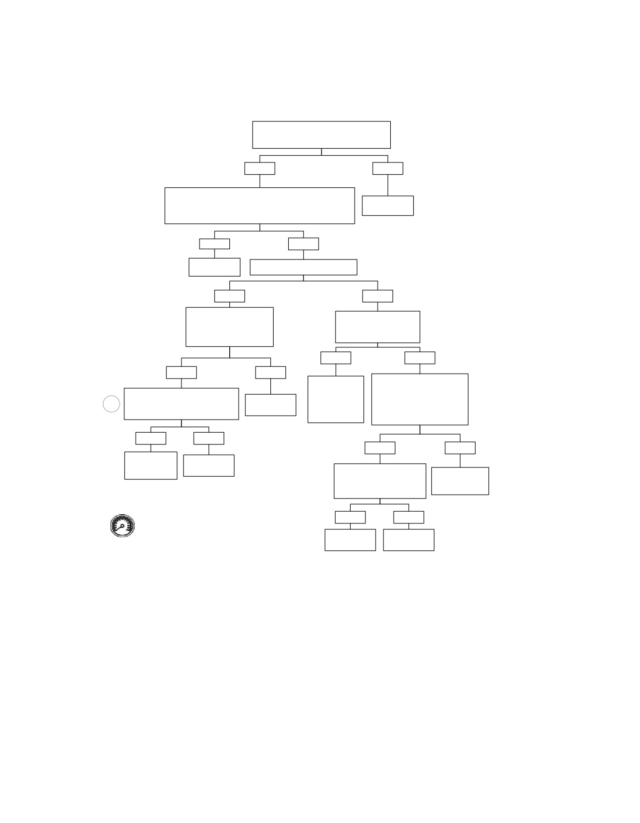
Front or Rear Brake Not Applied with Decel: DTC C1212
Clear the DTC. Operate the system under
the conditions for running the DTC.
Did the DTC reset?
YES
NO
Disconnect connector [166]. Apply Front and Rear Stop Lamp
Switch. Test for voltage on terminal “13” to ground and
Refer to
terminal “3” of connector [166B].
Diagnostic Tips.
Voltage present at both terminals?
YES
NO
Replace ABS
Is voltage present on terminal “3”?
Module.
YES
NO
Disconnect connector [22].
Apply the rear brake pedal.
Test terminal “1” connector
Does the stop lamp
[22B] for voltage.
illuminate?
Voltage present?
YES
NO
YES
NO
Disconnect Rear Stop Lamp
Repair open in
Switch. Apply rear brake pedal
Rear Brake input
Connect jumper wire from terminal
and test for continuity between
Repair open in
circuit terminal
1
“1” to terminal “2” of connector [22B].
terminals “1” and “2” of
(O/W) wire.
“3” of connector
Does the stop lamp illuminate?
connector [121A].
[166B].
Continuity present?
YES
NO
YES
NO
Replace Front
Repair open in
Stop Lamp
(R/BN) wire.
Turn the Ignition Switch ON.
Switch.
Replace Rear
Test terminal “1” of connector
Stop Lamp
[121B] for voltage.
Switch.
Voltage present?
Clear DTCs using speedometer self diagnostics.
YES
NO
See 2.3 SPEEDOMETER SELF DIAGNOSTICS.
Confirm proper operation with no check engine
lamp.
Repair open in
Repair open in
(PK/BN) wire.
(O/W) wire.
fc01576_en
6-66 2008 Touring Diagnostics: ABS
HOME
DTC C1214
6.21
DTC C1214: REAR BRAKE SWITCH
Action Taken When the DTC Sets
ALWAYS ON
No action is taken when this code is set. The ABS indicator
does not illuminate and the ABS is still active.
Circuit Description
Conditions for Clearing the DTC
The ABS module monitors the rear brake switch input. When
the brake pedal is applied the ABS module receives voltage
The condition for the DTC is no longer present and the DTC
on the rear brake switch circuit. The ABS module uses this
has been cleared with either a "WOW" test or Digital Techni-
signal to enhance ABS operation.
cian.
Conditions for Running the DTC
The ABS module automatically clears the historic DTC when
a current DTC is not detected in 50 consecutive drive cycles.
•
Ignition voltage is greater than 6.5V.
Diagnostic Tips
Conditions for Setting the DTC
The following conditions are possible causes for this fault:
The DTC will set if all of the following conditions exist for 2
seconds:
•
Short to voltage between the rear brake switch and the
ABS module.
•
The ABS module sees a rear brake input.
•
Rear brake switch stuck closed or applied during acceler-
•
The vehicle speed exceeds 25 MPH (40 km/h).
ation.
•
The vehicle acceleration exceeds
5 MPH/second (8
•
Internal rear brake sensing malfunction.
km/h/second).
2008 Touring Diagnostics: ABS 6-67
HOME
1C
Front Stop
em00157
[64-1]
ACCY
Lamp
Fuse
Switch
15 Amp
1D
[166B]
[166A]
ABS Module
1
2
[22A]
See appendix B
1
2
[22B]
main harness
page 1 of 3
PK/BN
[121-2B]
1
1
[121-1B]
O/W
5
5
O/W
[121-2A]
1
1
[121-1A]
Rear
[1B]
[1A]
Stop
R/BN
13
13
Front brake input
Pressure
Lamp
(Except FLHR)
Switch
Switch
Electronic
PK/BN
3
3
Rear brake input
Control
Module (ECM)
[78A] [78B]
Brake switch input
25
25
R/BE
4
3
2
1
[201B]
ABS
4
3
2
1
[201A]
Diode
Pack
Circuit Board
R/Y
6
6
R/Y
R/Y
4
4
3
3
R/Y
BK
5
5
BK
BK
6
6
4
4
BK
Brake Relay
O/V
3A
87
5
Tail/Stop
[7A] [7B]
[94B] [94A]
[93A] [93B]
R/Y
2B
30
3
See appendix B
Lamp
R/BE
2A
85
2
main harness
BK
3B
86
1
page 1 of 3
[64-2]
[GND 1A]
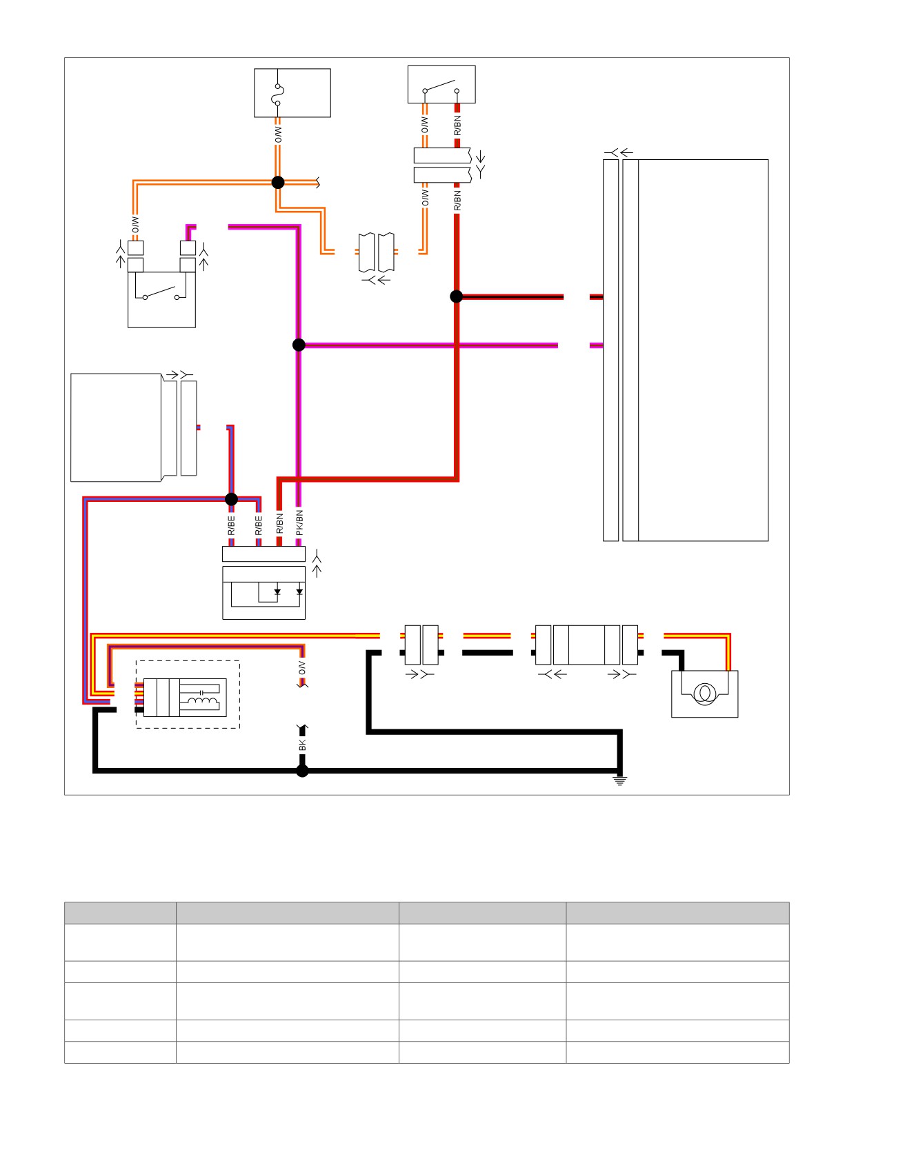
Figure 6-31. Brake Switches Schematic
Table 6-17. FLHX, FLHT/C/U Connector Locations
NO.
DESCRIPTION
TYPE
LOCATION
[1]
Main to interconnect harness
16-place Molex (black)
Inner fairing
- right radio support
bracket
[7]
Rear fender lights harness
8-place Multilock
Top of rear fender (under seat)
[22]
Interconnect to right handlebar
12-place Molex (black)
Inner fairing - right fairing support brace
switches
[64-1]
Fuse block
Packard
Under left side cover
[64-2]
Fuse block
Packard
Under left side cover
6-68 2008 Touring Diagnostics: ABS
HOME
Table 6-17. FLHX, FLHT/C/U Connector Locations
NO.
DESCRIPTION
TYPE
LOCATION
[78]
Electronic Control Module (ECM)
73-place Delphi
Under seat
[93]
T
ail lamp
4-place Multilock
Circuit board under tail lamp assembly
[94]
Rear fender light harness to circuit
6-place Multilock
Circuit board under tail lamp assembly
board
[121-1]
Rear brake switch
Spade terminals
Lower right side behind exhaust
[121-2]
Rear brake switch
Spade terminals
Lower right side behind exhaust
[166]
ABS module
20-place
Behind right side cover
[201]
ABS diode pack
4-place
Behind left side cover
2008 Touring Diagnostics: ABS 6-69
HOME
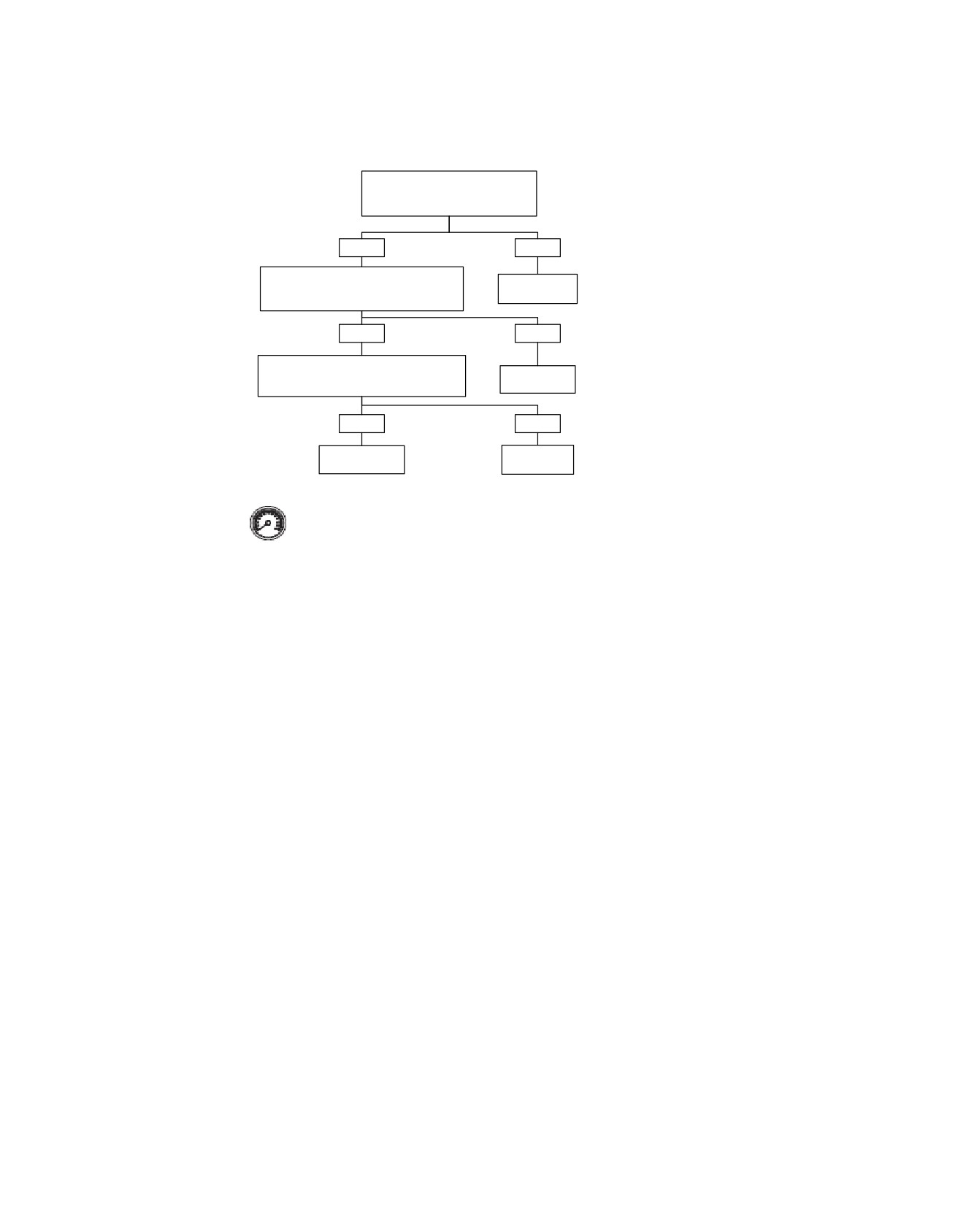
Rear Brake Switch Always On: DTC C1214
Clear the DTC. Operate the system in
the conditions for running the DTC.
Did the DTC reset?
YES
NO
Disconnect connector [166]. Test for voltage
Refer to
on terminal “3” of connector [166B].
Diagnostic Tips.
Voltage present?
YES
NO
Disconnect connector [121-1]. Test for
voltage on terminal “1” of connector [121-1B].
Replace ABS
Voltage present?
Module.
YES
NO
Repair short to
Replace rear
voltage.
brake switch.
fc01577_en
Clear DTCs using speedometer self diagnostics.
See 2.3 SPEEDOMETER SELF DIAGNOSTICS.
Confirm proper operation with no check engine lamp.
6-70 2008 Touring Diagnostics: ABS
HOME
DTC C1216
6.22
DTC C1216: REAR BRAKE SWITCH OPEN
Action Taken When the DTC Sets
No action is taken when this code is set. The ABS indicator
Circuit Description
DOES NOT illuminate and the ABS is still active.
The ABS module monitors the rear brake switch input. When
the brake pedal is applied the ABS module receives voltage
Conditions for Clearing the DTC
on the rear brake switch circuit. The ABS module uses this
The condition for the DTC is no longer present and the DTC
signal to enhance ABS operation.
has been cleared with either a "WOW" test or Digital Techni-
cian.
Conditions for Running the DTC
The ECU automatically clears the historic DTC when a current
•
Ignition voltage is greater than 6.5V.
DTC is not detected in 50 consecutive drive cycles.
•
The front brake switch is not closed (brake applied).
Diagnostic Tips
Conditions for Setting the DTC
The following conditions are possible causes for this fault:
The DTC will set if all of the following conditions exist for 2
•
An open or loose connection in the rear brake input circuit.
seconds:
•
All brake lamps are open or burned out.
•
The ABS module detects an open in the rear brake input
circuit.
•
The ground path to the brake lamps is open.
•
The ABS module detects an open in the ground circuit to
•
Internal ABS module problem in the rear brake input cir-
the rear brake switch.
cuitry.
2008 Touring Diagnostics: ABS 6-71
HOME
1C
Front Stop
em00157
[64-1]
ACCY
Lamp
Fuse
Switch
15 Amp
1D
[166B]
[166A]
ABS Module
1
2
[22A]
See appendix B
1
2
[22B]
main harness
page 1 of 3
PK/BN
[121-2B]
1
1
[121-1B]
O/W
5
5
O/W
[121-2A]
1
1
[121-1A]
Rear
[1B]
[1A]
Stop
R/BN
13
13
Front brake input
Pressure
Lamp
(Except FLHR)
Switch
Switch
Electronic
PK/BN
3
3
Rear brake input
Control
Module (ECM)
[78A] [78B]
Brake switch input
25
25
R/BE
4
3
2
1
[201B]
ABS
4
3
2
1
[201A]
Diode
Pack
Circuit Board
R/Y
6
6
R/Y
R/Y
4
4
3
3
R/Y
BK
5
5
BK
BK
6
6
4
4
BK
Brake Relay
O/V
3A
87
5
Tail/Stop
[7A] [7B]
[94B] [94A]
[93A] [93B]
R/Y
2B
30
3
See appendix B
Lamp
R/BE
2A
85
2
main harness
BK
3B
86
1
page 1 of 3
[64-2]
[GND 1A]
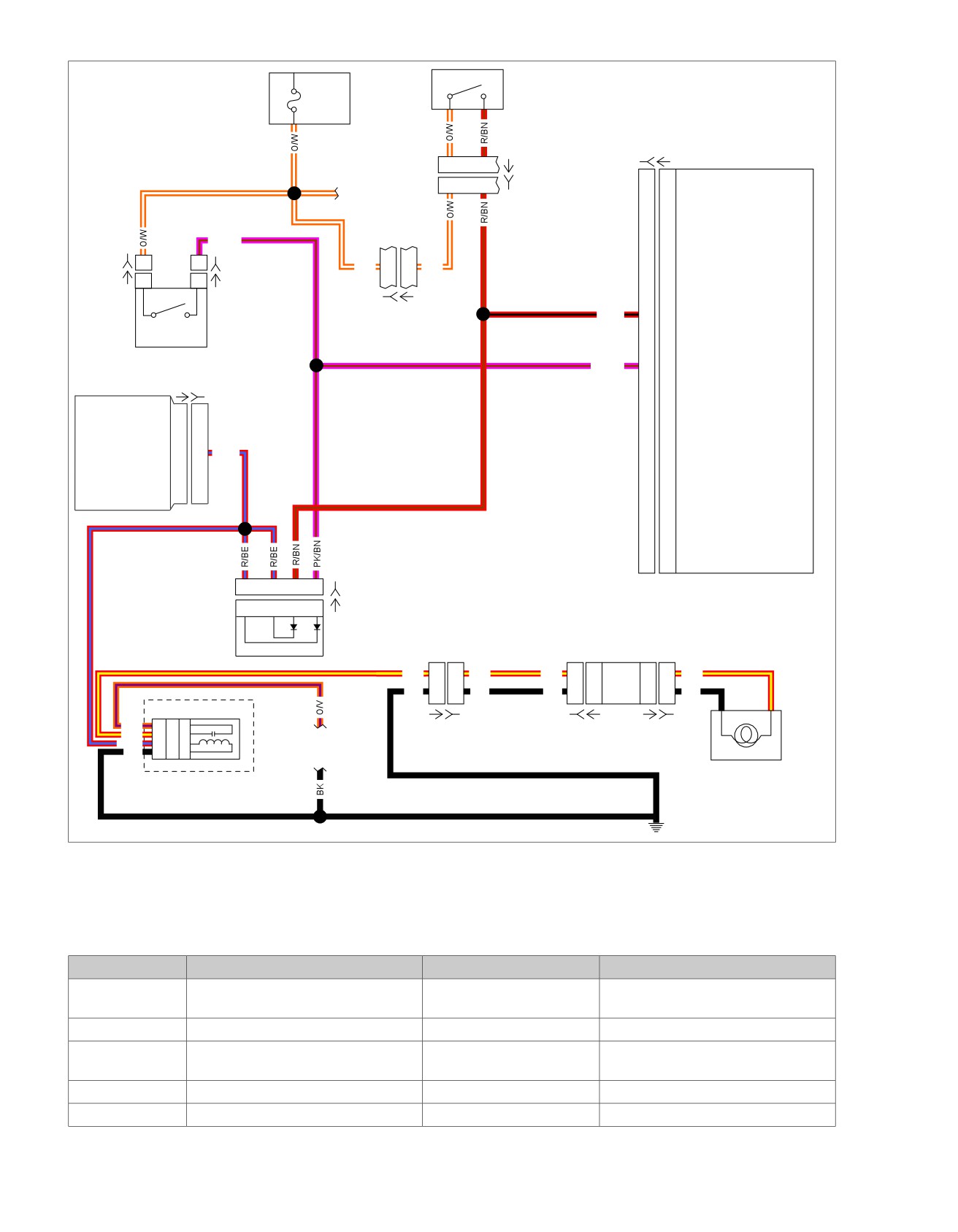
Figure 6-32. Brake Switches Schematic
Table 6-18. FLHX, FLHT/C/U Connector Locations
NO.
DESCRIPTION
TYPE
LOCATION
[1]
Main to interconnect harness
16-place Molex (black)
Inner fairing
- right radio support
bracket
[7]
Rear fender lights harness
8-place Multilock
Top of rear fender (under seat)
[22]
Interconnect to right handlebar
12-place Molex (black)
Inner fairing - right fairing support brace
switches
[64-1]
Fuse block
Packard
Under left side cover
[64-2]
Fuse block
Packard
Under left side cover
6-72 2008 Touring Diagnostics: ABS
HOME
Table 6-18. FLHX, FLHT/C/U Connector Locations
NO.
DESCRIPTION
TYPE
LOCATION
[78]
Electronic Control Module (ECM)
73-place Delphi
Under seat
[93]
T
ail lamp
4-place Multilock
Circuit board under tail lamp assembly
[94]
Rear fender light harness to circuit
6-place Multilock
Circuit board under tail lamp assembly
board
[121-1]
Rear brake switch
Spade terminals
Lower right side behind exhaust
[121-2]
Rear brake switch
Spade terminals
Lower right side behind exhaust
[166]
ABS module
20-place
Behind right side cover
[201]
ABS diode pack
4-place
Behind left side cover
2008 Touring Diagnostics: ABS 6-73
HOME
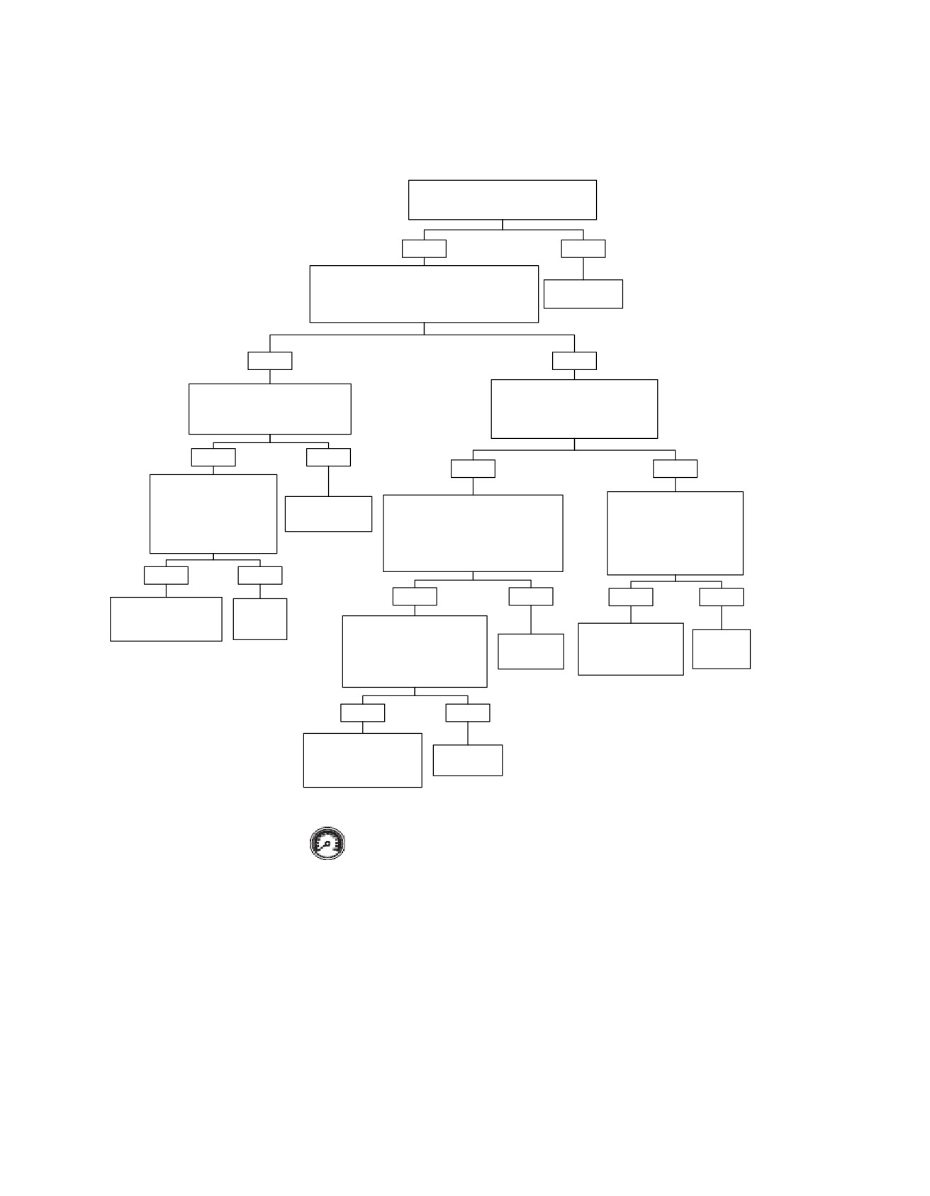
Rear Brake Switch Open: DTC C1216
Clear the DTC. Operate the system under
the conditions for running the DTC.
Did the DTC reset?
YES
NO
Connect ABS Breakout Box (HD-48642). Turn the
Ignition switch to the IGNITION position.
Refer to
Measure voltage at terminal “3” of Breakout Box.
Diagnostic Tips.
Is voltage greater then 2.0V?
YES
NO
Disconnect rear stop lamp switch
Apply rear brake switch. Measure
connector [22]. Measure voltage at
voltage drop from terminal “10” to
terminal “3” of Breakout Box.
terminal “3” of the Breakout Box.
Is voltage greater then 2.0V?
Is voltage drop greater then 2.0V?
YES
NO
YES
NO
Disconnect ABS diode pack
connector [201]. Measure
voltage at terminal “3" of
Replace Rear
Disconnect rear stop lamp switch
While performing wiggle test
Breakout Box.
Stop Lamp Switch.
connector [121-1] and connector [121-
measure voltage drop from
Is voltage greater then
2]. Jumper the two connectors together.
terminal “10” to terminal “3” of
Measure voltage drop from terminal “10”
the breakout box.
2.0V?
to terminal “3” of the Breakout Box.
Is voltage drop greater then
Is voltage drop greater then 2.0V?
2.0V?
YES
NO
YES
NO
YES
NO
Locate and repair short
Replace
to voltage on (PK/BN)
ABS Diode
Disconnect ABS diode pack
rear brake input circuit.
Pack.
Locate and repair high
connector [201]. Measure
Replace
Replace Rear
resistance short to
voltage drop from terminal “10”
Stop Lamp
ABS
to terminal “3” of Breakout Box.
ground on (PK/BN)
Switch.
Module.
Is voltage drop greater then
rear brake input circuit.
1.0V?
YES
NO
Locate and repair high
resistance short to ground
Replace ABS
on (PK/BN) rear brake
Diode Pack.
input circuit.
Clear DTCs using speedometer self diagnostics.
See 2.3 SPEEDOMETER SELF DIAGNOSTICS.
fc01578_en
Confirm proper operation with no check engine
lamp.
6-74 2008 Touring Diagnostics: ABS
HOME
DTC C1014,
C1055-C1066, C1118, C1121
6.23
DTC C1014, C1055-C1066, C1118, C1121:
Conditions for Clearing the DTC
ECU INTERNAL FAULT
Certain conditions that may cause this DTC to set cannot be
cleared. Other conditions that may cause this DTC to set may
Circuit Description
be cleared, at least temporarily, with either a "WOW" test or
The ABS module monitors the voltage level available for system
Digital Technician.
operation. A low voltage condition prevents the system from
Diagnostic Tips
operating properly. The ABS module also performs several
self-tests for internal problems which may affect proper opera-
The following conditions are possible causes for this fault:
tion.
•
Internal system malfunction.
Conditions for Running the DTC
•
A faulty system voltage supply to the module.
•
Ignition voltage is greater than 6.5V.
•
A faulty system ground.
Conditions for Setting the DTC
Diagnostic Notes
The ABS module detects an internal malfunction.
Each reference number below correlates to a circled number
on the flow chart(s).
Action Taken When the DTC Sets
1. The ignition circuit consists of all the circuitry back to and
•
ABS is disabled.
including the ignition switch.
•
The ABS indicator is illuminated.
2008 Touring Diagnostics: ABS 6-75
HOME
em00156
MAXIFUSE
[77B] [77A]
[5B]
40 Amp
Voltage
BK
2
2
BK
Regulator
Electronic
B A
Control Unit (ECU)
BK
Hydraulic
Control Unit
R
R
R
(HCU)
1
1
Pump motor supply
IGN
I
A
R/BK
Pump
OFF
B
B
R
M
Motor
A
C
R/GY
ACC
FLHR
2
2
Pump motor ground
C
[222A]
Battery
only
Ignition
[33A]
[33B]
C
[222B]
Switch
1E
4A
[64-2]
Ignition
ABS Motor
Fuse
Fuse
[64-1]
15 Amp
30 Amp
1C ACCY
Fuse
1F
4B
15 Amp
1D
R/V
R/V
20
20
Battery (Motor)
R/V
10
10
Battery
See appendix B
O/W
main harness
GY
GY
19
19
Ignition
PK/BN
page 1 of 3
[121-2B]
1
1
[121-1B]
Front
O/W
5
5
O/W
O/W
1
1
O/W
Stop
[121-2A]
1
1
[121-1A]
Lamp
Switch
Rear
R/BN
2
2
R/BN
Stop
[1B]
[1A]
Pressure
Lamp
Switch
Switch
(Except FLHR)
[22B]
[22A]
PK/BN
3
3
Rear brake input
R/BN
13
13
Front brake input
See appendix B main
Speedometer
LGN/V
harness page 1 of 3
(FLHR Only)
Serial data
2
2
LGN/V
2
2
LGN/V
LGN/V
9
9
Serial data
4
3
2
1
[201B]
ABS Diode
4
3
2
1
[201A]
[20A]
[20B]
Pack
[39A]
[39B]
BK/V
18
18
Front wheel speed sensor low
BK/BE
17
17
Front wheel speed sensor high
[167B]
B A
BE/BN
8
8
Rear wheel speed sensor high
[167A]
B A
BE/V
7
7
Rear wheel speed sensor low
A
B
[168B]
A
B
[168A]
2
[108B]
2
[108A]
R/Y
Front
Brake Relay
Wheel
Tachometer
Speed
3A
87
5
Rear
2B
30
3
Sensor
Wheel
2A
85
2
BK
1
1
Ground
3B
86
1
Speed
Sensor
See appendix B
[64-2]
main harness
BK
BK
11
11
Ground (Motor)
page 1 of 3
Circuit Board
6
6
R/Y
4
4
3
3
R/Y
[166B] [166A]
5
5
BK
6
6
4
4
BK
See appendix B
main harness
Tail/Stop
page 1 of 3
[7A]
[7B]
[94B] [94A]
[93A] [93B]
Lamp
BK
BK
GND 1A
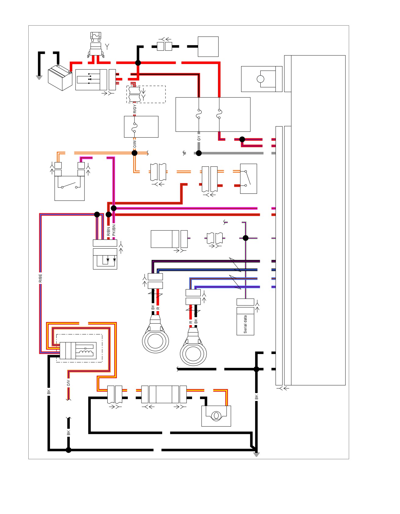
Figure 6-33. ABS Schematic
6-76 2008 Touring Diagnostics: ABS

HOME
Table 6-19. FLHX, FLHT/C/U Connector Locations
NO.
DESCRIPTION
MODEL
TYPE
LOCATION
[1]
Main to interconnect har-
ALL
16-place Molex (black)
Inner fairing - right radio support bracket
ness
[5]
MAXIFUSE
ALL
2-place Packard
Under left side cover
[7]
Rear fender lights harness
ALL
8-place Multilock
Top of rear fender (under seat)
[20]
Console harness
ALL
16-place Molex
Under seat
[22]
Interconnect
to
right
ALL
12-place Molex (black)
Inner fairing - right fairing support brace
handlebar switches
[33]
Ignition switch
ALL
3-place Packard
Inner fairing - under radio (front of Ignition
Switch housing)
[39]
Speedometer
FLHT/C/U
12-place Packard
Inner fairing (back of speedometer)
FL
TR
12-place Packard
Under bezel (back of speedometer)
[64-1]
Fuse block
ALL
Packard
Under left side cover
[64-2]
Fuse block
ALL
Packard
Under left side cover
[77]
Voltage regulator
ALL
2-place Lyall
Bottom of voltage regulator (right side)
[93]
T
ail lamp
ALL
4-place Multilock
Circuit board under tail lamp assembly
[94]
Rear
fender light harness to
ALL
6-place Multilock
Circuit board under tail lamp assembly
circuit board
[108]
T
achometer
ALL
12-place Packard
Inner fairing (back of tachometer)
[121-1]
Rear brake light switch
ALL
Spade terminals
Bottom of rear frame downtube (right side)
[121-2]
Rear brake light switch
ALL
Spade terminals
Bottom of rear frame downtube (right side)
[166]
ABS module
ALL
20-place Molex
Under right side cover
[167]
Front wheel speed sensor
ALL
2-place Packard
Below fuel tank (left side)
[168]
Rear wheel speed sensor
FLHX/FLHT/
2-place Packard
Fairing
FLTR
FLHR
Inside headlamp nacelle
[201]
ABS diode pack
ALL
4-place Deutsch
Under left side cover
[222]
Main to ignition harness
ALL
4-place Packard
Rear of fuel tank
2008 Touring Diagnostics: ABS 6-77
HOME
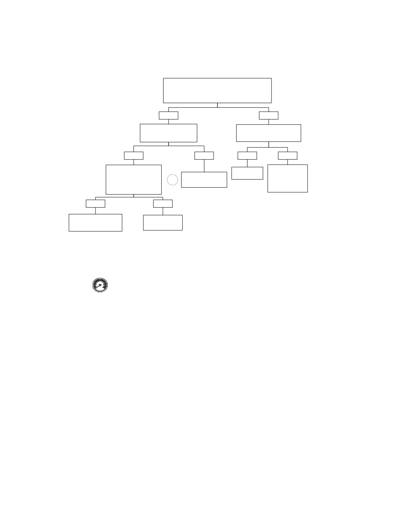
ECU Internal Fault: DTC C1014, C1055-C1066, C1118, C1121
Install Breakout Box (HD-48642). Turn the Ignition
Switch to the IGNITION position. Using a DVOM test for
voltage at the Battery circuits at terminals “20” and “10”
Is the voltage above 10.5V?
YES
NO
Test the ignition circuit
Test battery circuit terminals “10”
terminal “19” for voltage.
and “20” for high resistance.
Is voltage above 10.5V?
High resistance present?
YES
NO
YES
NO
Test the ground circuits at
Repair Battery and
terminals “1” and “11” for
Repair circuit.
charging system.
Repair high resistance
Refer to section 1.7
high resistance or an open.
1
in ignition circuit.
CHARGING
Is high resistance or open
present?
SYSTEM.
YES
NO
Repair high resistance or
Replace ABS
open condition on ground
Module.
circuits.
Clear DTCs using speedometer self diagnostics.
See 2.3 SPEEDOMETER SELF DIAGNOSTICS.
fc01579_en
Confirm proper operation with no check engine lamp.
6-78 2008 Touring Diagnostics: ABS
HOME
DTC U1300,
U1301 OR BUS ER
6.24
DIAGNOSTICS
Diagnostic Tips
The typical serial data voltage range is 0 volts (inactive) to 7
•
If serial data is shorted, these Diagnostic Trouble Codes
volts (active). Due to the short pulse, voltages will be much
(DTCs) will automatically cause the check engine lamp to
lower on a DVOM. In analog mode, a DVOM reading serial
illuminate. The odometer will read "BUS Er" in this condi-
data will show continuous voltage when active, typically 0.6-
tion.
0.8 volts. The range for acceptable operations is 0-7.0 volts.
•
DTCs P1009 and P1010 may accompany DTCs U1300
and U1301.
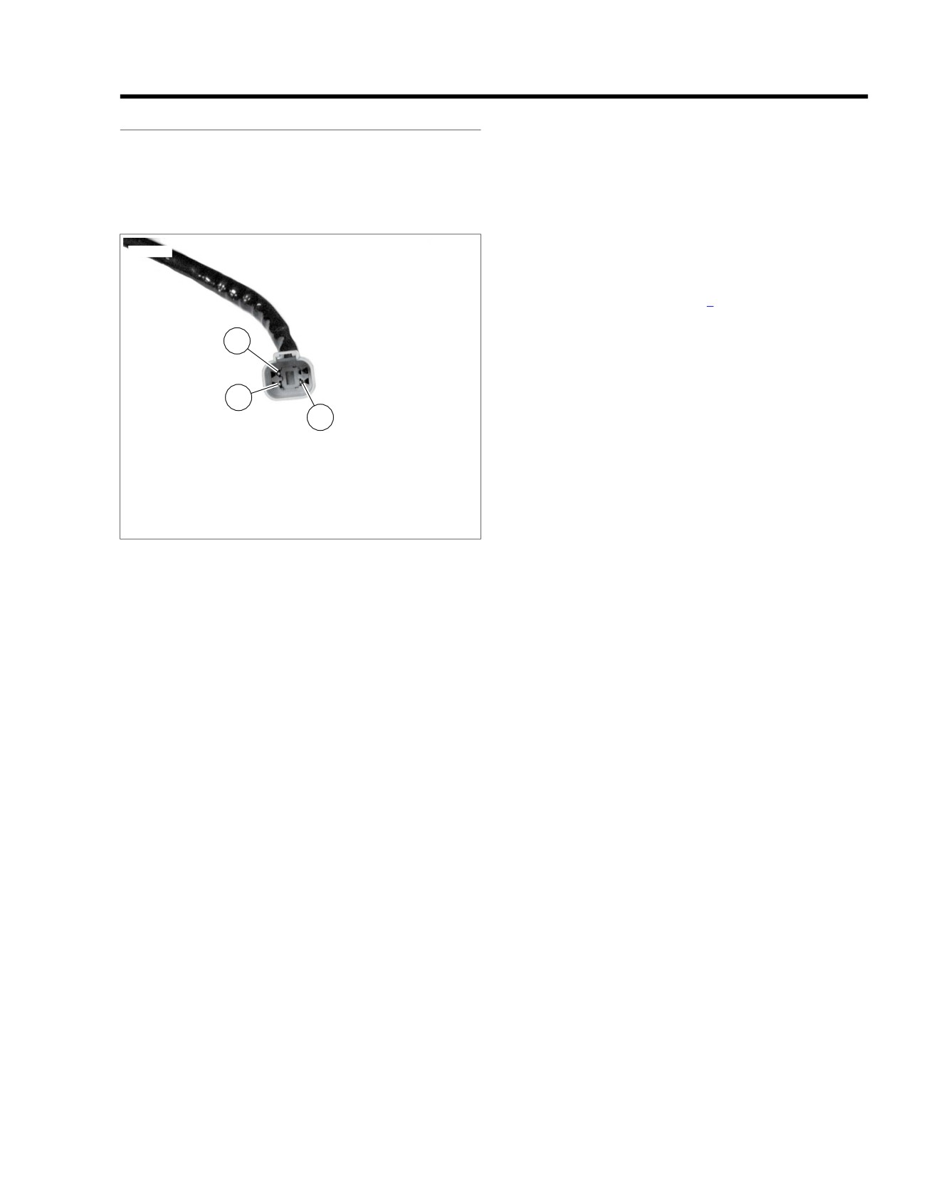
ed02982
Diagnostic Notes
If a U1300, U1301 or "BUS Er" is present, perform diagnostic
procedures listed in 4.12 STARTS, THEN STALLS.
3
2
1
1. Terminal 2: ground (BK/GN)
2. Terminal 3: serial data (LGN/V)
3. Terminal 4: power (GY)
Figure 6-34. Data Link Connector
2008 Touring Diagnostics: ABS 6-79
NOTES
6-80 2008 Touring Diagnostics: ABS