Harley Davidson 2008 Touring Models. Electrical Diagnostics Manual - page 28
HOME
ANTILOCK BRAKE SYSTEM (ABS) GENERAL
INFORMATION
6.1
ANTILOCK BRAKE SYSTEM (ABS)
ed01292
DESCRIPTION
Antilock Brake System (ABS)
3
The Antilock Brake System (ABS) module controls brake
2
application under extreme stopping conditions in order to keep
4
the wheels from slipping. When wheel slip is detected during
a brake application, an ABS event occurs. The hydraulic
pressure to the individual wheel is controlled to prevent slipping
on that wheel. Specific valves and individual hydraulic lines
1
are provided for each wheel. The ABS can decrease, hold, or
increase fluid pressure to each brake. However, the ABS
cannot increase hydraulic pressure above the pressure being
transmitted by the master cylinder.
During an ABS event, a series of rapid pulsations may be felt
in either the front brake lever or rear brake pedal. These
pulsations are caused by the rapid changes in position of the
individual solenoid valves as the ABS responds to wheel speed
sensor inputs and attempts to prevent wheel slip. These
pulsations are present only during initialization and antilock
braking. The pulsations stop when normal braking is resumed
or when the vehicle comes to a stop. A ticking or popping noise
may also be heard as the solenoid valves cycle rapidly. During
1.
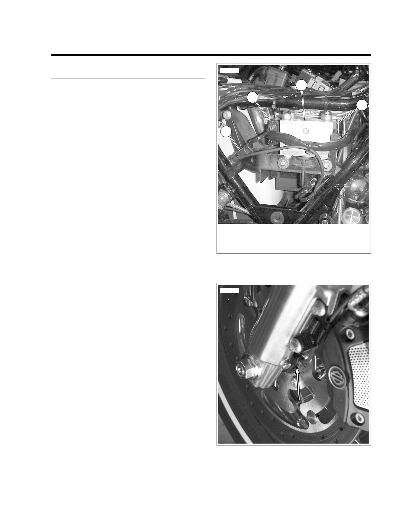
Rear Wheel Speed Sensor Connector
antilock braking on dry pavement intermittent chirping noises
2.
Electronic Contol Unit (ECU) Connector
may be heard as the tires approach slipping. These noises and
3.
Hydraulic Control Unit (HCU)
pulsations are considered normal during antilock operation.
4.
Electronic Control Unit (ECU)
Vehicles equipped with ABS may be stopped by applying
Figure 6-1. ABS Module
normal force to the brake pedal or lever. Brake operation during
normal braking is no different then that of previous non-ABS
systems. Maintaining a constant force on the brake pedal or
lever provides the shortest stopping distance while maintaining
vehicle stability.
ed01293
In addition to the normal brake system, the Antilock Brake
System consists of the following components.
•
See Figure 6-1. Electronic Control Unit (ECU): The ECU
contains the motor relay, valve relay, system enable relay,
and the solenoids.
•
See Figure 6-1. Hydraulic Control Unit (HCU): The HCU
contains the four valves (an apply valve and release valve
for each wheel), two pumps, pump motor, and accumu-
lators.
•
See Figure 6-2. Front Wheel Speed Sensor.
•
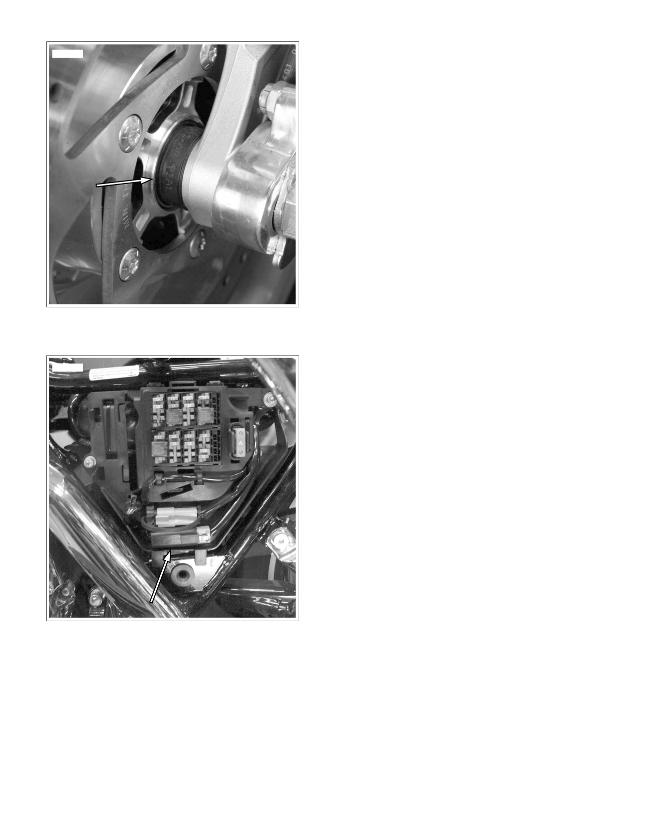
See Figure 6-3. Rear Wheel Speed Sensor.
•
See Figure 6-4. ABS Diode Pack.
When referencing the ECU and the HCU as a unit they are
referred to as the Antilock Brake System (ABS) module.
Figure 6-2. Front Wheel Speed Sensor
2008 Touring Diagnostics: ABS 6-1
HOME
release valve is opened. The excess fluid is stored in the
ed01295
accumulator until the pump can return the fluid to the master
cylinder or fluid reservoir.
Pressure Increase
After the wheel slip is corrected, a pressure increase occurs.
The ECU increases the pressure to individual wheels during
deceleration in order to reduce the speed of the wheel. The
apply valve is opened and the release valve is closed. The
increased pressure is delivered from the master cylinder and
will not exceed the pressure from the master cylinder.
Initialization Self-Test
The ABS module performs one initialization test each ignition
cycle. The ABS module verifies internal circuitry and the wheel
speed sensor circuits.
As part of the initialization self test the ABS module also does
a modular test. This test consists of energizing the actuators,
and commanding the motor and solenoids on and off. The ABS
module will run this test the first time the vehicle speed exceeds
10 MPH (16 km/h) in an ignition cycle or when all the following
conditions are met for the first time in an ignition cycle:
•
Brake switch is not applied.
Figure 6-3. Rear Wheel Speed Sensor
•
Engine is above 500 RPM.
•
No ABS event present.
•
The system ECU is enabled.
ed01342
•
The ABS system is not communicating with Digital Tech-
nician.
ABS Indicator
See Figure 6-5. The Instrument Module (IM) illuminates the
ABS indicator when the following occurs.
•
The ECU detects an ABS disabling malfunction. The ECU
sends a serial data message to the instrument requesting
illumination.
•
The IM performs a bulb check.
•
The IM detects a loss of communication with the ECU.
The ECU sends a message to the instrument when a malfunc-
tion that disables ABS operation is detected. Depending on
the fault the ABS Indicator may stay on even after the malfunc-
tion is corrected. The indicator will not go off until the vehicle
is operated at speeds greater than
10 MPH (16 km/h). It is
important to verify that this is not the cause of an ABS indicator
which is illuminated when no DTCs are set, before attempting
to diagnose other possible causes.
Figure 6-4. ABS Diode Pack
Pressure Hold
The ECU closes the apply valve and keeps the release valve
closed in order to isolate the slipping wheel when wheel slip
occurs. This holds the pressure steady on the brake so that
the hydraulic pressure does not increase or decrease.
Pressure Decrease
If a pressure hold does not correct the wheel slip condition, a
pressure decrease occurs. The apply valve is closed and the
6-2 2008 Touring Diagnostics: ABS
HOME
Self Diagnostics. See 6.2 SPEEDOMETER SELF DIA-
ed01172
GNOSTICS.
•
A historic DTC is also cleared after a total of 50 ignition
cycles (start and run cycle) has elapsed. After the 50
ignition cycle retention period, the DTC is automatically
60
40
erased from memory providing that no subsequent faults
50
70
30
50
40
80
of the same type are detected in that period.
30
90
20
60
MPH
RPM x100
20
100
Current
10
70
10
110
Current DTCs are those which are present during the current
0
120
0
80
ignition cycle. See the appropriate flow charts for solutions.
I
D
D
Historic
If a particular problem happens to resolve itself, the active
status problem is dropped and it becomes a historic DTC rather
than a current DTC.
Historic DTCs are stored for 50 ignition cycles after any DTC
was last set as current to assist in the diagnosis of intermittent
1
2
3
4
5
6
7
8
faults. On the 50th cycle, the DTC will clear itself. The security
lamp will only indicate the existence of historic DTCs for two
ignition cycles.
It is important to note that historic DTCs may also be present
1.
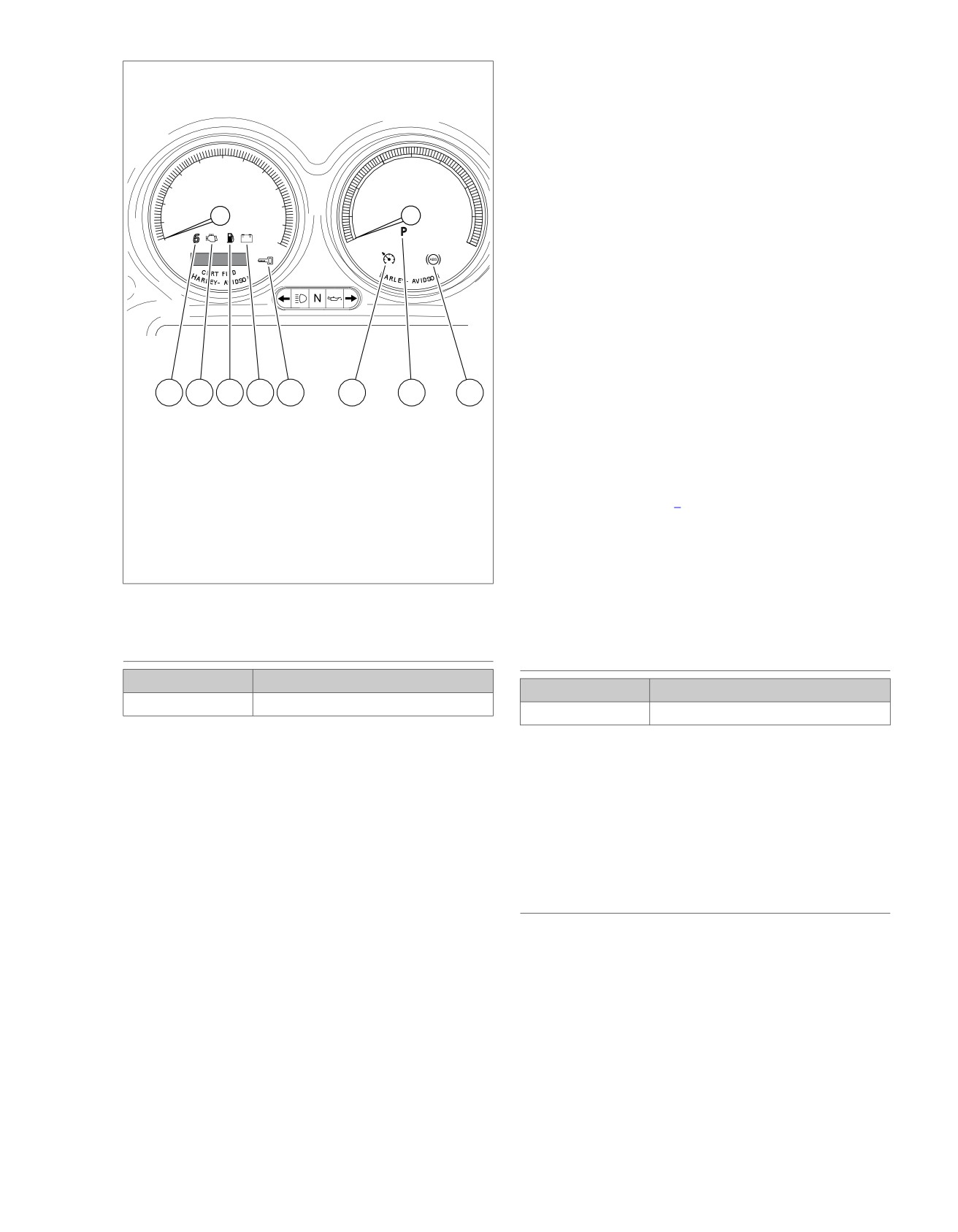
Sixth gear indicator
whenever the system indicates the existence of a current fault.
2.
Check engine lamp
See 6.1 ANTILOCK BRAKE SYSTEM (ABS) GENERAL
3.
Low fuel
INFORMATION, Multiple Trouble Codes if multiple DTCs are
4.
Battery
found.
5.
Security lamp (key icon)
6.
Cruise Enabled (If Applicable)
Diagnostic charts are designed for use with current DTCs and
7.
Pursuit (If Applicable)
as a result they frequently suggest wire repair or part replace-
8.
ABS (If Applicable)
ment. When diagnosing a historic DTC the charts can be helpful
but should not lead to part replacement without verification the
Figure 6-5. Instrument
part is faulty.
RETRIEVING DIAGNOSTIC TROUBLE
CODE TYPES
CODES
PART NUMBER
TOOL NAME
PART NUMBER
TOOL NAME
HD-44750
DIGITAL TECHNICIAN
HD-44750
DIGITAL TECHNICIAN
There are two types of DTCs: current and historic. If a DTC is
There are two levels of diagnostics:
stored, it can be read using either a computer based diagnostic
package called DIGITAL TECHNICIAN (Part No. HD-44750)
•
The most sophisticated mode uses a computer-based
or Speedometer Self Diagnostics. See 6.2 SPEEDOMETER
diagnostic package called the DIGITAL TECHNICIAN (Part
SELF DIAGNOSTICS.
No. HD-44750).
NOTES
•
The second mode requires using speedometer self dia-
gnostics. TSM/TSSM/HFSM, ABS, and ECM codes can
•
Speedometer Self Diagnostics will display both current
be accessed and cleared. See 6.2 SPEEDOMETER SELF
and historic DTCs. To differentiate between current and
DIAGNOSTICS for more information.
historic DTCs a computer based diagnostic package called
DIGITAL TECHNICIAN (Part No. HD-44750) must be
MULTIPLE TROUBLE CODES
employed.
While it is possible for more than one fault to occur and set
•
All
DTCs reside in the memory of ECM,
more than one DTC, there are several conditions which may
TSM/TSSM/HFSM, speedometer, tachometer, or ABS
result in one fault setting multipleDTCs:
module until the DTC is cleared by using Speedometer
Serial data codes (DTC U1300, U1301, U1016, U1097 and
U1098) may be accompanied by other codes. Always correct
the serial data codes before resolving the other codes.
2008 Touring Diagnostics: ABS 6-3
HOME
SPEEDOMETER SELF DIAGNOSTICS
6.2
Odometer Reset Switch, turn Ignition Switch to ON.
GENERAL
Background lighting should illuminate, gauge needles
The speedometer is capable of displaying and clearing
should sweep their full range of motion and indicator lamps
speedometer, tachometer, TSM/HFSM, ABS, and Electronic
controlled by the serial data bus (battery and check engine)
Control Module (ECM) Diagnostic Trouble Codes (DTCs)
should illuminate.
(diagnostic mode).
•
If speedometer fails "WOW" test, check for battery, ground
DIAGNOSTICS
and accessory to speedometer. If any feature in the
speedometer is non-functional, see 6.4
INITIAL DIA-
Diagnostic Tips
GNOSTIC CHECK: ABS.
•
For a quick check of speedometer function, a "WOW" test
can be performed. See Figure 6-6. While pressing the Trip
ed01553
8
3
1
2
11
1
11
60
40
50
70
30
50
40
80
30
90
20
60
MPH
RPM x100
20
100
10
70
10
110
0
120
0
80
9
IF
D
D
7
7
2
6
10
9
8
5
4
10
4
5
6
FLHT, FLTR & FLHX
FLHR
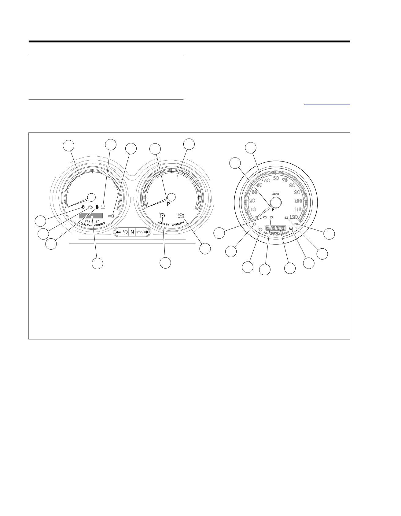
1.
Speedometer
7. Check engine lamp
2.
Security lamp (key icon)
8. Battery discharge lamp
3.
Tachometer
9. Sixth gear lamp
4.
Cruise lamp
10. ABS lamp
5.
Odometer/trip odometer/clock
11. Pursuit lamp
6.
Low fuel warning lamp
Figure 6-6. Instrument
6-4 2008 Touring Diagnostics: ABS
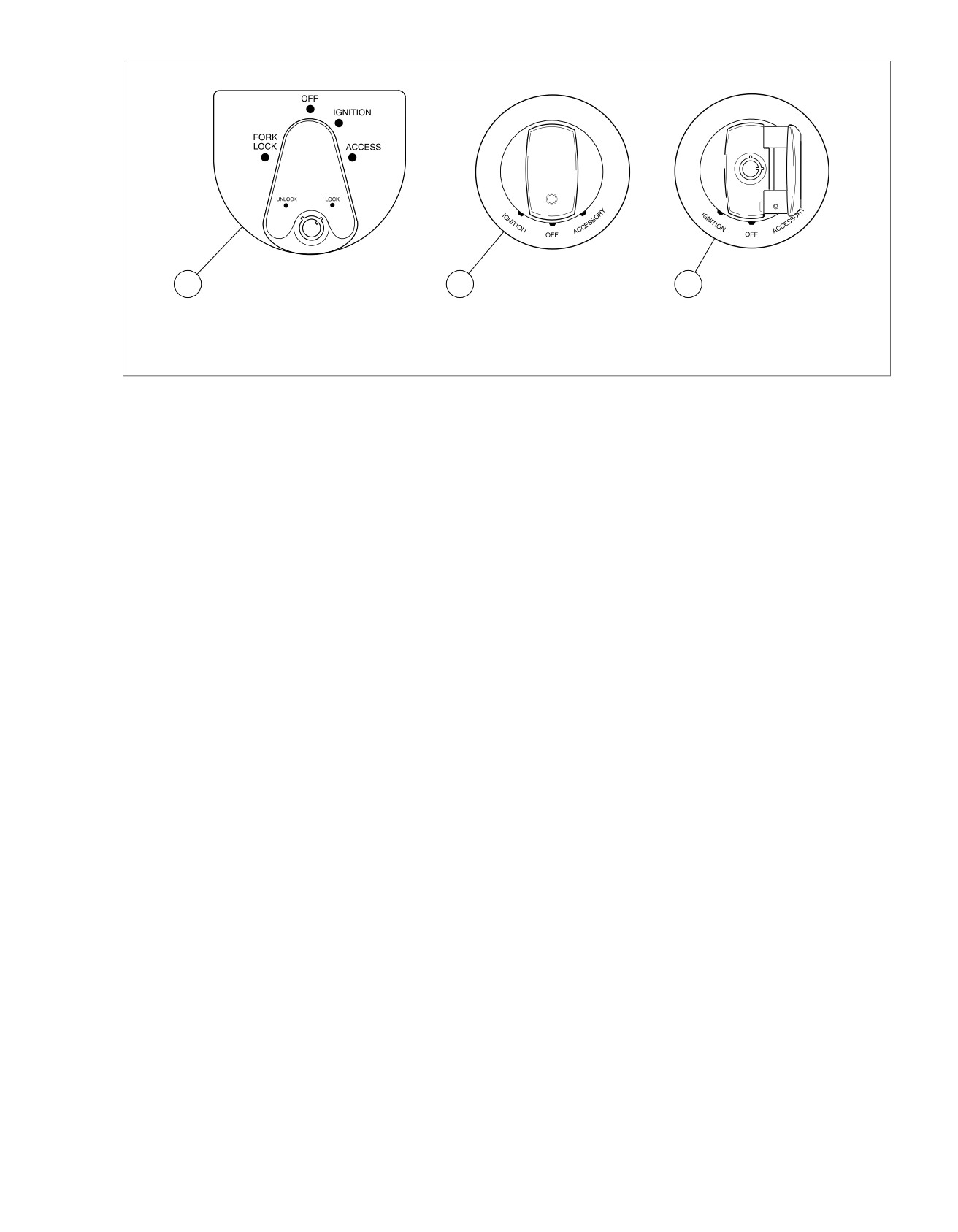
HOME
ed01552
1
2
3
1. All except FLHR models
2. All FLHR models (cover shown closed)
3. All FLHR models (cover shown open)
Figure 6-7. Ignition Switch: Touring Models
Diagnostic Notes
2. To clear DTCs for selected module, press Trip Odometer
Reset Switch for more than 5 seconds when code is dis-
Each reference number below correlates to a circled number
played. This procedure will clear all DTCs for selected
on the flow chart(s).
module.
1. To exit diagnostic mode, turn ignition switch OFF.
2008 Touring Diagnostics: ABS 6-5
HOME
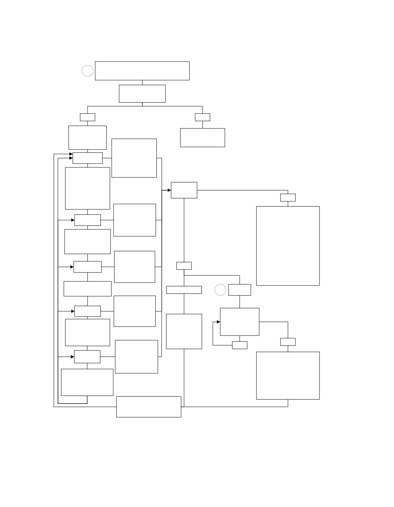
Speedometer Self Diagnostics
While holding Trip Odometer Reset Switch in, turn
1
Ignition Switch to IGNITION.
Make sure Engine Stop Switch is in RUN position.
Release Trip Odometer
Reset Switch.
Does “diag” appear?
YES
NO
Press and release
See 2.2 INITIAL
Trip Odometer
DIAGNOSTIC CHECK:
Reset Switch.
To display DTCs for
SPEEDOMETER.
“PSSPtb” appears?
the Electronic Control
Module (ECM), press
”P” flashing.
and hold Trip
Odometer Reset
Switch for more than 5
To choose Turn Signal
seconds.
Module/Turn Signal
Security Module/
Hands Free Security
Device
Module (TSM/TSSM/
response?
HFSM), press and
NO
release trip odometer
reset switch.
To display DTCs for
TSM/TSSM/HFSM,
“no rsp” displayed.
press and Trip
See applicable code from other
”S” flashing.
modules. Models not equipped
Odometer Reset
with a Tachometer or ABS will
Switch for more than
To choose
display “no rsp” normally.
5 seconds.
Speedometer,
If “no rsp” displayed on
press and release the
Odometer on Tachometer
Trip Odometer Reset
equipped vehicle, see 2.4
Switch.
SPEEDOMETER/
To display DTCs for
TACHOMETER.
Speedometer, press
If “no rsp” displayed on
and hold Trip
YES
Odometer on ABS equipped
”SP” flashing.
Odometer Reset
vehicle, see 6.1 ANTILOCK
Switch for more than
BRAKE SYSTEM (ABS)
5 seconds.
GENERAL INFORMATION.
To choose Tachometer,
DTC
press and release Trip
“none” displayed.
2
Odometer Reset Switch.
displayed.
To display DTCs for
Tachometer, press
and hold Trip
”t” flashing.
Press and release
Odometer Reset
Trip Odometer
Switch for more than
Press and release
To choose Anti-Lock
Reset Switch.
5 seconds.
Trip Odometer
Brake System (ABS),
Are more DTCs
Reset Switch.
press and release Trip
displayed?
Part number of
Odometer Reset
module will be
Switch.
NO
To display DTCs for
displayed.
YES
ABS (if equipped),
press and hold Trip
”b” flashing.
“end” displayed.
Odometer Reset
To clear all DTCs for selected
Switch for more than
module press and hold Trip
5 seconds.
Odometer Reset Switch for more
To choose ECM, press
than 5 seconds.
and release Trip Odometer
If DTCs are not to be cleared,
Reset Switch.
Press and release Trip Odometer
To exit, turn Ignition Switch
Reset Switch. Part number of
to OFF.
module will be displayed.
Press and release Trip Odometer
Reset Switch again to continue to
next module.
fc01087_en
6-6 2008 Touring Diagnostics: ABS
HOME
BREAKOUT BOX:
ABS
6.3
GENERAL
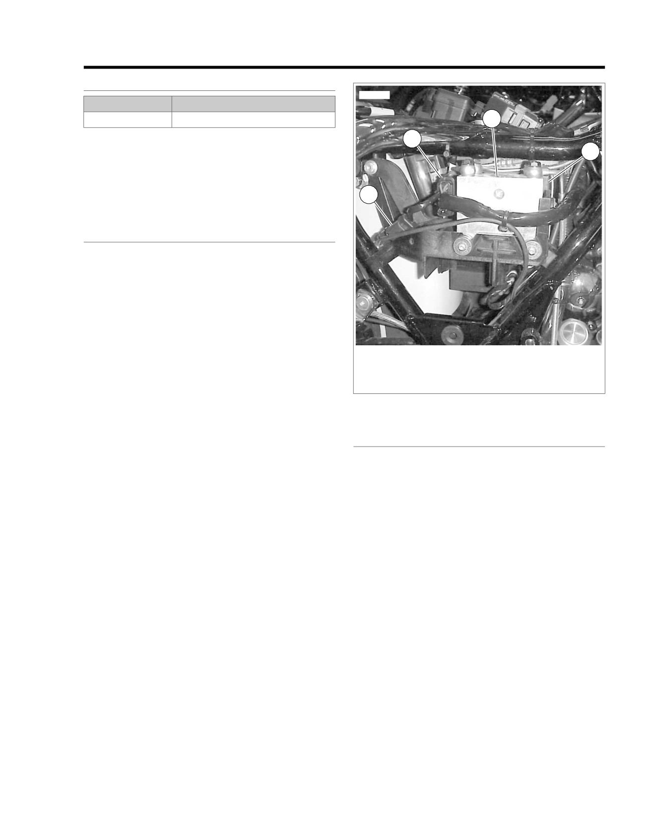
ed01292
PART NUMBER
TOOL NAME
HD-48642
BREAKOUT BOX
3
The BREAKOUT BOX (Part No. HD-48642) connects to the
2
Antilock Brake System (ABS) module connector [166]. Used
4
in conjunction with a DVOM, it allows circuit diagnosis of wiring
harness and connections without having to probe with sharp
objects.
1
NOTE
See wiring diagrams for ABS terminal functions.
INSTALLATION
1. Depress latch on connector [166B].
2. Connect Harness Adapters to connectors [166A] and
[166B].
3. Attach Breakout Box to connector(s).
4. Attach connectors from Breakout Box to Harness Adapters.
1. Rear Wheel Speed Sensor Connector
2. Electronic Control Unit (ECU) Connector [166A]
3. Hydraulic Control Unit (HCU)
4. Electronic Control Unit (ECU)
Figure 6-8. Electronic Control Unit (ECU) Location
REMOVAL
1. Detach connectors from Breakout Box to Harness
Adapters.
2. Detach Harness Adapters from connectors [166A] and
[166B].
3. Install connector [166B] to ABS Module.
2008 Touring Diagnostics: ABS 6-7

HOME
INITIAL DIAGNOSTIC CHECK:
ABS
6.4
GENERAL
INITIAL DIAGNOSTICS
To locate faulty circuits or other system problems, follow the
Diagnostic Tips
diagnostic flow charts and tests in this section. For a systematic
•
If speedometer reads "No Response" with the ignition
approach, always begin with
6.4 INITIAL DIAGNOSTIC
switch turned to IGNITION (engine stop switch at RUN
CHECK: ABS, Initial Diagnostics. Read the general information
with the engine off), check data link for an open or short
and then work your way through the flow chart box by box.
to ground between data link connector [91A] terminal "3"
Diagnostic Notes
and ECM, TSM/TSSM/HFSM, speedometer connector or
tachometer (if equipped) connector. See 3.10 INITIAL
If a numbered circle appears adjacent to a flow chart box, then
DIAGNOSTIC CHECK: TSM/HFSM.
more information is offered in the diagnostic notes. Many dia-
gnostic notes contain supplemental information, descriptions
•
Check for an open data test terminal between data link
of various diagnostic tools or references to other parts of the
connector [91A] terminal "3" and ECM. With Ignition Switch
manual where information on the location and removal of
turned to IGNITION, serial data bus voltage should be
components may be obtained.
typically 0.6-0.8 volts. The range of acceptable operation
is 0-7.0 volts.
Circuit Diagram/Wire Harness Connector
•
If speedometer reads "BUS Er" (serial data bus error),
Table
refer to flow charts in 4.5 INITIAL DIAGNOSTIC CHECK:
When working through a flow chart, refer to the illustrations,
EFI.
the associated circuit diagram and the wire harness connector
table as necessary. The wire harness connector table for each
Diagnostic Notes
circuit diagram identifies the connector number, description,
Each reference number below correlates to a circled number
type and general location.
on the flow chart(s).
In order to perform most diagnostic routines, a Breakout Box
1. Compare engine behavior to symptoms tables in 4.5 INI-
and a DVOM are required. See 6.3 BREAKOUT BOX: ABS.
TIAL DIAGNOSTIC CHECK: EFI.
To perform the circuit checks with any degree of efficiency, a
All ABS Diagnostic Trouble Codes
(DTCs)
are
listed
in
familiarity with the various wire connectors is also necessary.
Table 6-1.
Job/Time Code Values
Dealership technicians filing warranty claims should use the
job/time code values printed in bold text underneath the
appropriate repair.
Table 6-1. ABS Diagnostic Trouble Codes (DTCs) and Fault Conditions
DTC
RANKING
FAULT CONDITION
SOLUTION
C0562
18
Device voltage low
6.6 DTC C0562
C0563
19
System voltage high
6.7 DTC C0563
C1014
10
ECU internal fault
6.23 DTC C1014, C1055-C1066, C1118, C1121
C1017
17
Pump motor power circuit open
6.8 DTC C1017
fault
C1018
16
Pump
motor ground high resist-
6.9 DTC C1018
ance fault
C1021
22
Front wheel speed sensor
6.10 DTC C1021, C1023
equals 0
C1023
23
Rear wheel speed sensor
6.10 DTC C1021, C1023
equals 0
C1025
24
Front wheel speed signal inter-
6.11 DTC C1025, C1027, C1206, C1208
mittent
C1027
25
Rear wheel speed signal inter-
6.11 DTC C1025, C1027, C1206, C1208
mittent
C1032
20
Front
wheel speed sensor circuit
6.12 DTC C1032, C1034
open or shorted
C1034
21
Rear
wheel speed sensor circuit
6.12 DTC C1032, C1034
open or shorted
6-8 2008 Touring Diagnostics: ABS

HOME
Table 6-1. ABS Diagnostic Trouble Codes (DTCs) and Fault Conditions
DTC
RANKING
FAULT CONDITION
SOLUTION
C1042
11
Pump motor open
6.13 DTC C1042
C1043
12
Pump motor stalled
6.14 DTC C1043
C1055
1
ECU internal fault
6.23 DTC C1014, C1055-C1066, C1118, C1121
C1056
2
ECU internal fault
6.23 DTC C1014, C1055-C1066, C1118, C1121
C1057
3
ECU internal fault
6.23 DTC C1014, C1055-C1066, C1118, C1121
C1061
4
ECU internal fault
6.23 DTC C1014, C1055-C1066, C1118, C1121
C1062
4
ECU internal fault
6.23 DTC C1014, C1055-C1066, C1118, C1121
C1065
6
ECU internal fault
6.23 DTC C1014, C1055-C1066, C1118, C1121
C1066
7
ECU internal fault
6.23 DTC C1014, C1055-C1066, C1118, C1121
C1094
28
Front brake switch always on
6.15 DTC C1094
C1095
29
Front brake switch open
6.16 DTC C1095
C1118
8
ECU internal fault
6.23 DTC C1014, C1055-C1066, C1118, C1121
C1121
9
ECU internal fault
6.23 DTC C1014, C1055-C1066, C1118, C1121
C1151
33
Front wheel release too long
6.17 DTC C1151
C1153
34
Rear wheel release too long
6.18 DTC C1153
C1158
15
Calibration
programming
6.19 DTC C1158
required
C1206
26
Wheel speed sensor frequency
6.11 DTC C1025, C1027, C1206, C1208
out of range
C1208
27
Wheel speed sensor frequency
6.11 DTC C1025, C1027, C1206, C1208
out of range
C1212
32
Front or rear brake not applied
6.20 DTC C1212
with decel
C1214
30
Rear brake switch always on
6.21 DTC C1214
C1216
31
Rear brake switch open
6.22 DTC C1216
U1300
13
Serial data low
6.24 DTC U1300, U1301 OR BUS ER
U1301
14
Serial data open/high
6.24 DTC U1300, U1301 OR BUS ER
Security Module (TSSM) or Hands-Free Security Module
Other Diagnostic Trouble Codes (DTCs)
(HFSM).
See 3.10 INITIAL DIAGNOSTIC CHECK: TSM/HFSM for any
See 4.5 INITIAL DIAGNOSTIC CHECK: EFI for any DTCs
DTCs related to the Turn Signal Module (TSM), Turn Signal
related to the Electronic Control Module (ECM).
2008 Touring Diagnostics: ABS 6-9
HOME
em00160
1
2
3
12
[30B]
1
2
3
12
[30A]
TSM/HSFM
1
2
5
7
[39B]
1
2
5
7
[39A]
Speedometer
15A
Instruments
1
To
Fuse
BK/GN
2
BN/GY
ignition
Data Link
relay
LGN/V
3
Connector
15A
Battery
4
GY
Fuse
[91A]
15A
Ignition
Fuse
[166A]
[166B]
Serial data
9
9
LGN/V
ABS Module
[78B]
69
[78A]
69
ECM
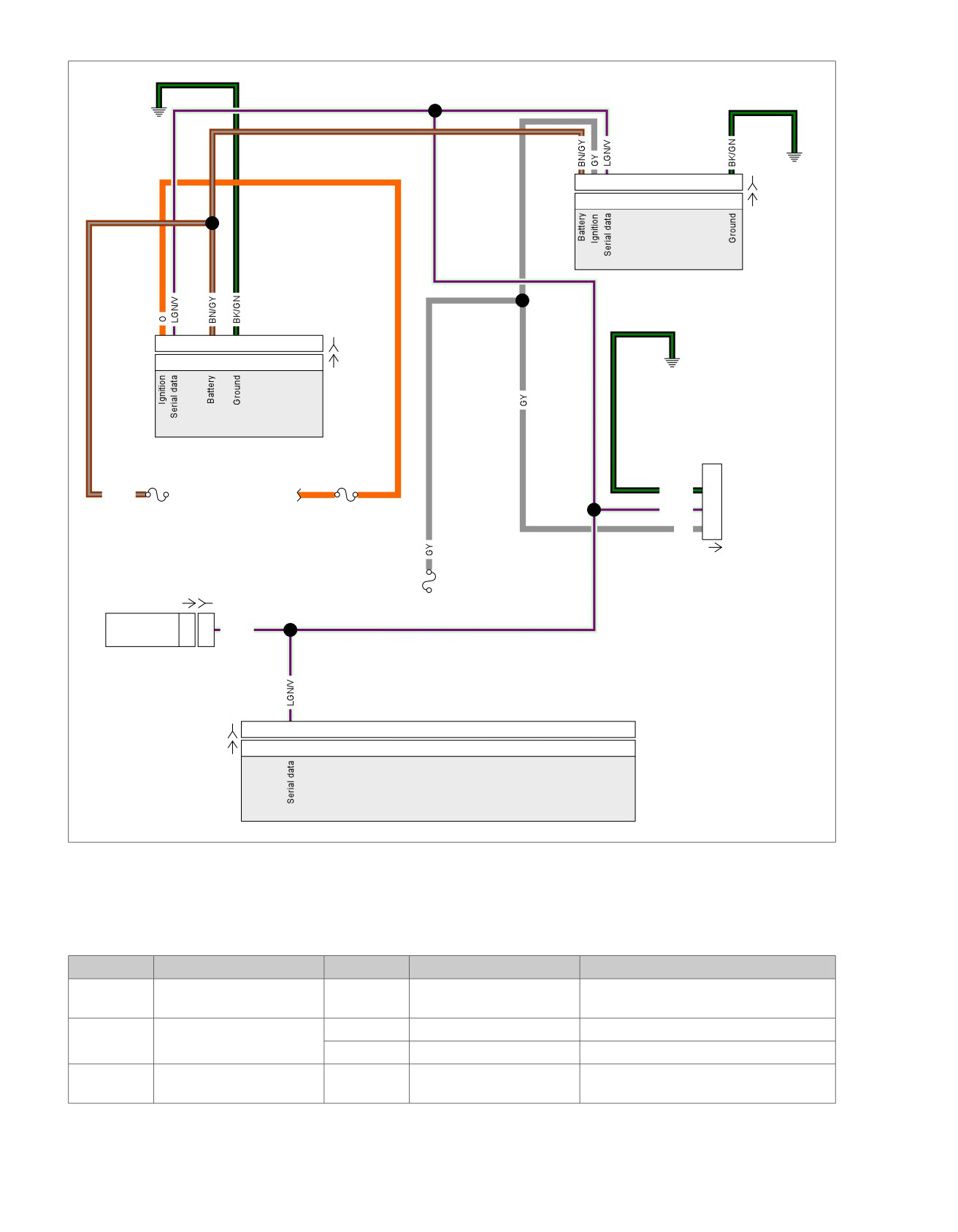
Figure 6-9. Diagnostic Check
Table 6-2. Wire Harness Connectors
NO.
DESCRIPTION
MODEL
TYPE
LOCATION
[30]
TSM/TSSM/HFSM
All
12-place Deutsch
Crossmember at rear of battery box (under
seat)
[39]
Speedometer
FLHT/C/U
12-place Packard
Inner fairing (back of speedometer)
FLTR
12-place Packard
Under bezel (back of speedometer)
[78]
Electronic Control Module
All
73-place Packard
Under seat
(ECM)
6-10 2008 Touring Diagnostics: ABS
HOME
Table 6-2. Wire Harness Connectors
NO.
DESCRIPTION
MODEL
TYPE
LOCATION
[91]
Data link connector
All
4-place Deutsch
Under left side cover
[166]
ABS module
All
20-place Molex
Under right side cover
2008 Touring Diagnostics: ABS 6-11
HOME
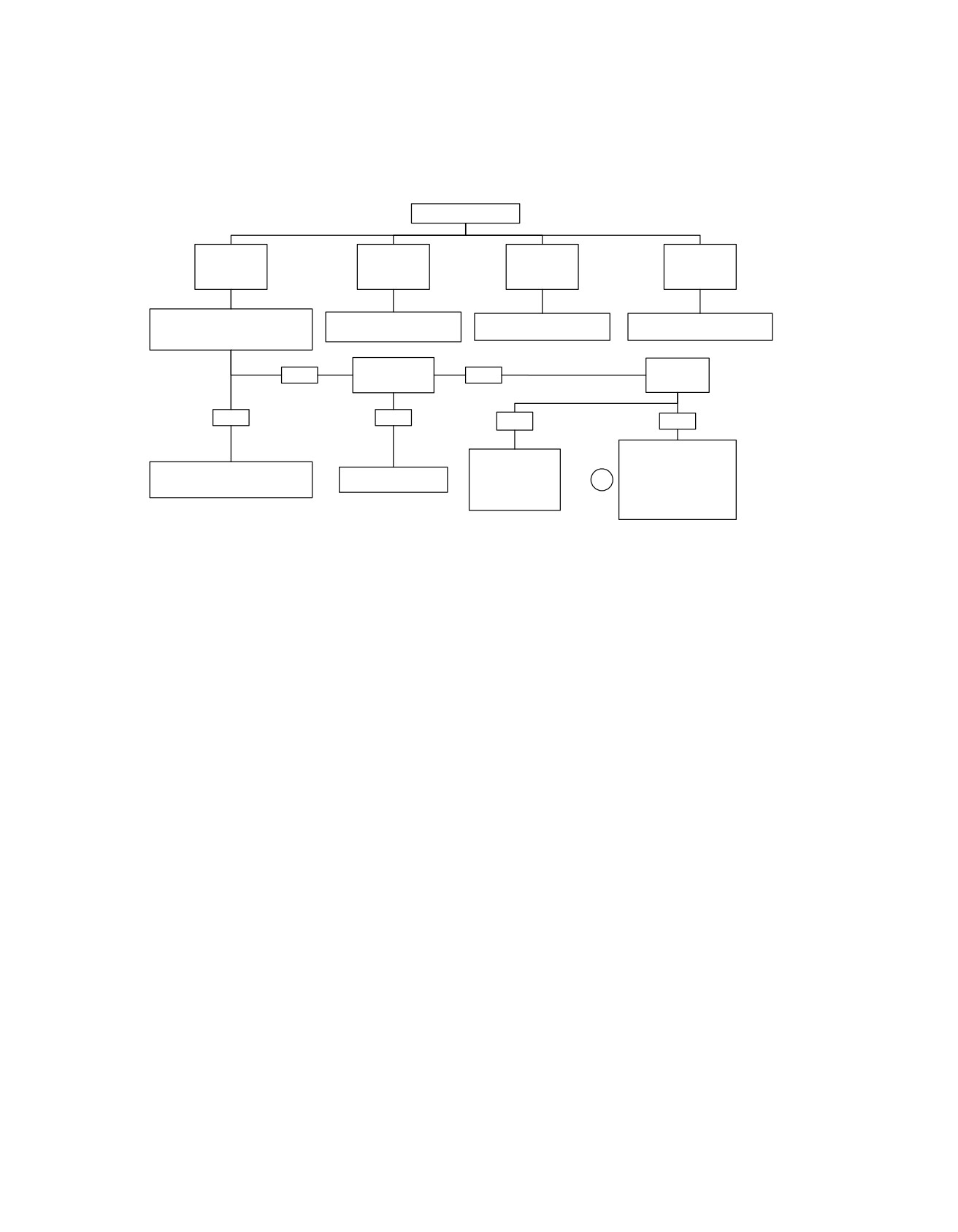
Diagnostic Check
Does Engine start?
YES.
YES.
NO.
NO.
Starts and
Starts, then
Cranks, but
Engine will not
runs.
stalls.
will not start.
crank.
Check for Diagnostic Trouble
See 4.12 STARTS, THEN
See 4.10 ENGINE CRANKS,
See 1.2 STARTING SYSTEM
Codes (DTCs).
STALLS.
BUT WILL NOT START.
DIAGNOSIS.
DTCs found?
Is Speedometer
“None”
NO
YES
functional?
Displayed?
YES
NO
NO
YES
No codes displayed. For
Go to Trip Switch
symptoms that may not
Refer to applicable DTC priority
Inoperable/Trip
set diagnostic trouble
Go to Section 2.
1
chart. DTCs are listed by priority.
Switch Closed
codes, refer to Table 2-1
DTC: B1008.
Speedometer Function
Chart-Loss Of Input.
fc01556_en
6-12 2008 Touring Diagnostics: ABS
HOME
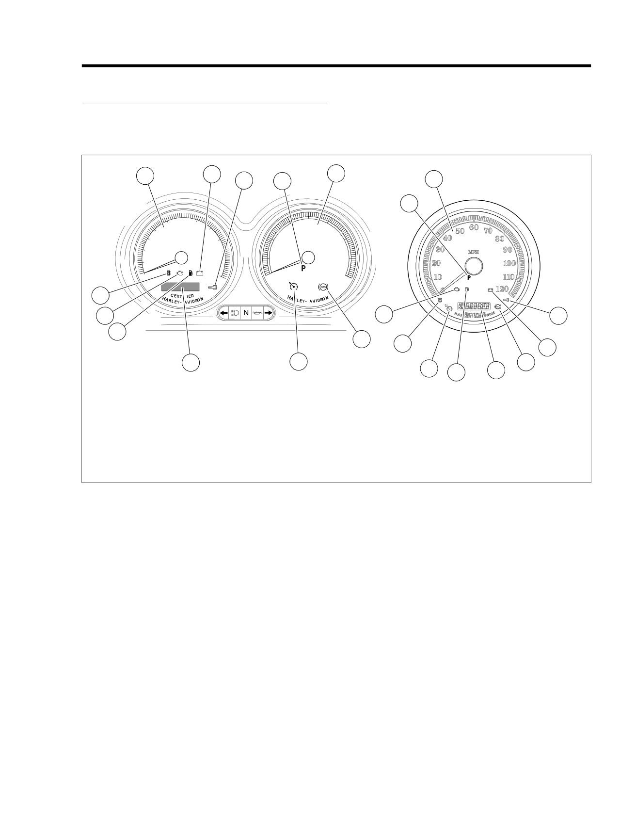
ABS INDICATOR DIAGNOSTICS
6.5
serial data message to the instrument in order to command
ABS INDICATOR ALWAYS ON OR
the indicator ON or OFF.
INOPERATIVE
Circuit Description
See Figure 6-10. The Instrument illuminates the ABS indicator
by supplying ground to the lamp. The ABS module sends a
ed01553
1
8
3
2
11
1
11
60
40
50
70
30
50
40
80
30
90
20
60
MPH
RPM x100
20
100
10
70
10
110
0
120
0
80
9
IF
D
D
7
7
2
6
10
9
8
5
4
10
4
5
6
FLHT, FLTR & FLHX
FLHR
1.
Speedometer
7. Check engine lamp
2.
Security lamp (key icon)
8. Battery discharge lamp
3.
Tachometer
9. Sixth gear lamp
4.
Cruise lamp
10. ABS lamp
5.
Odometer/trip odometer/clock
11. Pursuit lamp
6.
Low fuel warning lamp
Figure 6-10. Instrument
Diagnostic Tips
The malfunction must be present during diagnosis in order to
prevent unnecessary parts replacement.
2008 Touring Diagnostics: ABS 6-13
HOME
em00156
MAXIFUSE
[77B] [77A]
[5B]
40 Amp
Voltage
BK
2
2
BK
Regulator
Electronic
B A
Control Unit (ECU)
BK
Hydraulic
Control Unit
R
R
R
(HCU)
1
1
Pump motor supply
IGN
I
A
R/BK
Pump
OFF
B
B
R
M
Motor
A
C
R/GY
ACC
FLHR
2
2
Pump motor ground
C
[222A]
Battery
only
Ignition
[33A]
[33B]
C
[222B]
Switch
1E
4A
[64-2]
Ignition
ABS Motor
Fuse
Fuse
[64-1]
15 Amp
30 Amp
1C ACCY
Fuse
1F
4B
15 Amp
1D
R/V
R/V
20
20
Battery (Motor)
R/V
10
10
Battery
See appendix B
O/W
main harness
GY
GY
19
19
Ignition
PK/BN
page 1 of 3
[121-2B]
1
1
[121-1B]
Front
O/W
5
5
O/W
O/W
1
1
O/W
Stop
[121-2A]
1
1
[121-1A]
Lamp
Switch
Rear
R/BN
2
2
R/BN
Stop
[1B]
[1A]
Pressure
Lamp
Switch
Switch
(Except FLHR)
[22B]
[22A]
PK/BN
3
3
Rear brake input
R/BN
13
13
Front brake input
See appendix B main
Speedometer
LGN/V
harness page 1 of 3
(FLHR Only)
Serial data
2
2
LGN/V
2
2
LGN/V
LGN/V
9
9
Serial data
4
3
2
1
[201B]
ABS Diode
4
3
2
1
[201A]
[20A]
[20B]
Pack
[39A]
[39B]
BK/V
18
18
Front wheel speed sensor low
BK/BE
17
17
Front wheel speed sensor high
[167B]
B A
BE/BN
8
8
Rear wheel speed sensor high
[167A]
B A
BE/V
7
7
Rear wheel speed sensor low
A
B
[168B]
A
B
[168A]
2
[108B]
2
[108A]
R/Y
Front
Brake Relay
Wheel
Tachometer
Speed
3A
87
5
Rear
2B
30
3
Sensor
Wheel
2A
85
2
BK
1
1
Ground
3B
86
1
Speed
Sensor
See appendix B
[64-2]
main harness
BK
BK
11
11
Ground (Motor)
page 1 of 3
Circuit Board
6
6
R/Y
4
4
3
3
R/Y
[166B] [166A]
5
5
BK
6
6
4
4
BK
See appendix B
main harness
Tail/Stop
page 1 of 3
[7A]
[7B]
[94B] [94A]
[93A] [93B]
Lamp
BK
BK
GND 1A
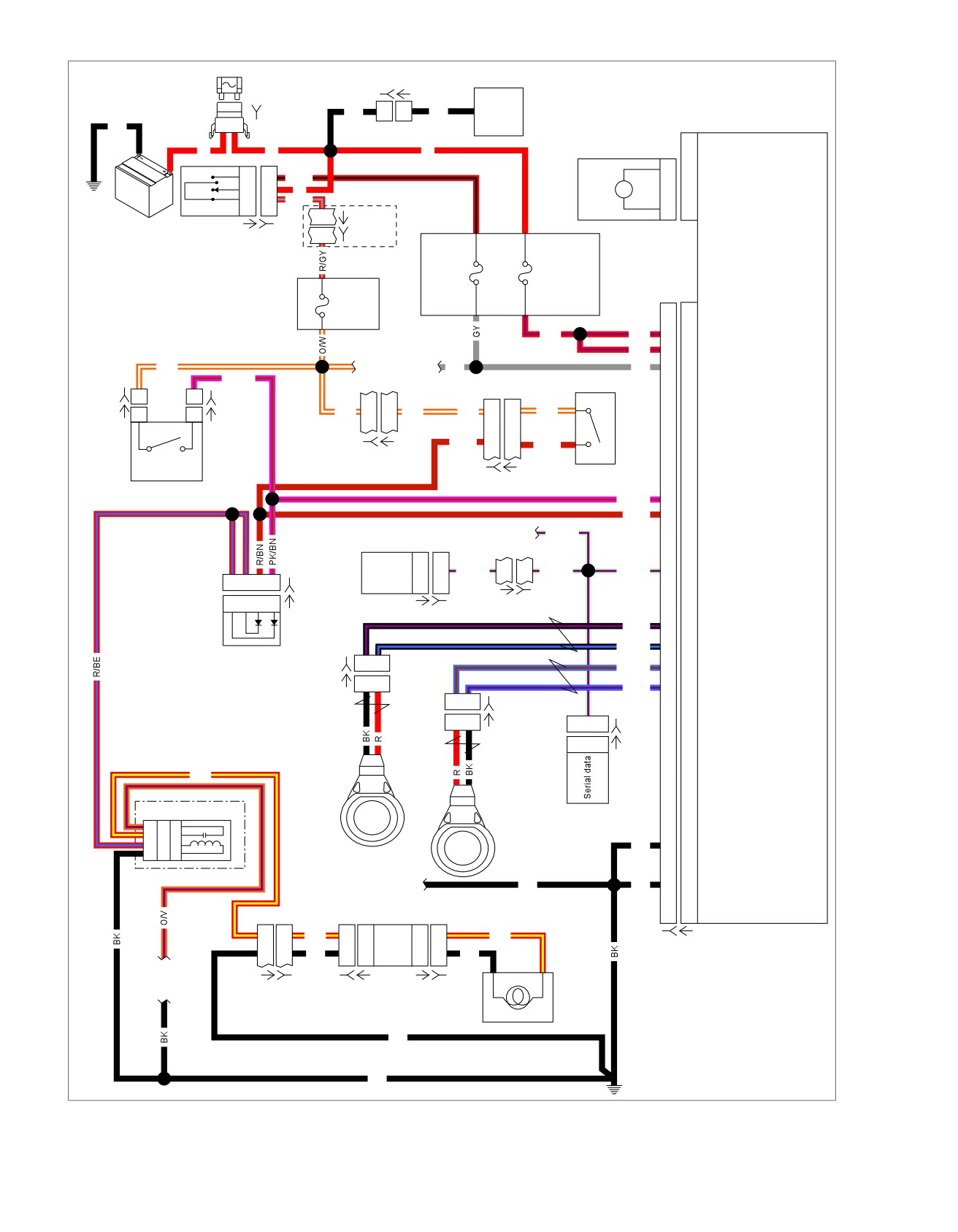
Figure 6-11. ABS Schematic
6-14 2008 Touring Diagnostics: ABS

HOME
Table 6-3. FLHX, FLHT/C/U Connector Locations
NO.
DESCRIPTION
MODEL
TYPE
LOCATION
[1]
Main to interconnect har-
ALL
16-place Molex (black)
Inner fairing - right radio support bracket
ness
[5]
MAXIFUSE
ALL
2-place Packard
Under left side cover
[7]
Rear fender lights harness
ALL
8-place Multilock
Top of rear fender (under seat)
[20]
Console harness
ALL
16-place Molex
Under seat
[22]
Interconnect
to
right
ALL
12-place Molex (black)
Inner fairing - right fairing support brace
handlebar switches
[33]
Ignition switch
ALL
3-place Packard
Inner fairing - under radio (front of Ignition
Switch housing)
[39]
Speedometer
FLHT/C/U
12-place Packard
Inner fairing (back of speedometer)
FL
TR
12-place Packard
Under bezel (back of speedometer)
[64-1]
Fuse block
ALL
Packard
Under left side cover
[64-2]
Fuse block
ALL
Packard
Under left side cover
[77]
Voltage regulator
ALL
2-place Lyall
Bottom of voltage regulator (right side)
[93]
T
ail lamp
ALL
4-place Multilock
Circuit board under tail lamp assembly
[94]
Rear
fender light harness to
ALL
6-place Multilock
Circuit board under tail lamp assembly
circuit board
[108]
T
achometer
ALL
12-place Packard
Inner fairing (back of tachometer)
[121-1]
Rear brake light switch
ALL
Spade terminals
Bottom of rear frame downtube (right side)
[121-2]
Rear brake light switch
ALL
Spade terminals
Bottom of rear frame downtube (right side)
[166]
ABS module
ALL
20-place Molex
Under right side cover
[167]
Front wheel speed sensor
ALL
2-place Packard
Below fuel tank (left side)
[168]
Rear wheel speed sensor
FLHX/FLHT/
2-place Packard
Fairing
FLTR
FLHR
Inside headlamp nacelle
[201]
ABS diode pack
ALL
4-place Deutsch
Under left side cover
[222]
Main to ignition harness
ALL
4-place Packard
Rear of fuel tank
2008 Touring Diagnostics: ABS 6-15
HOME
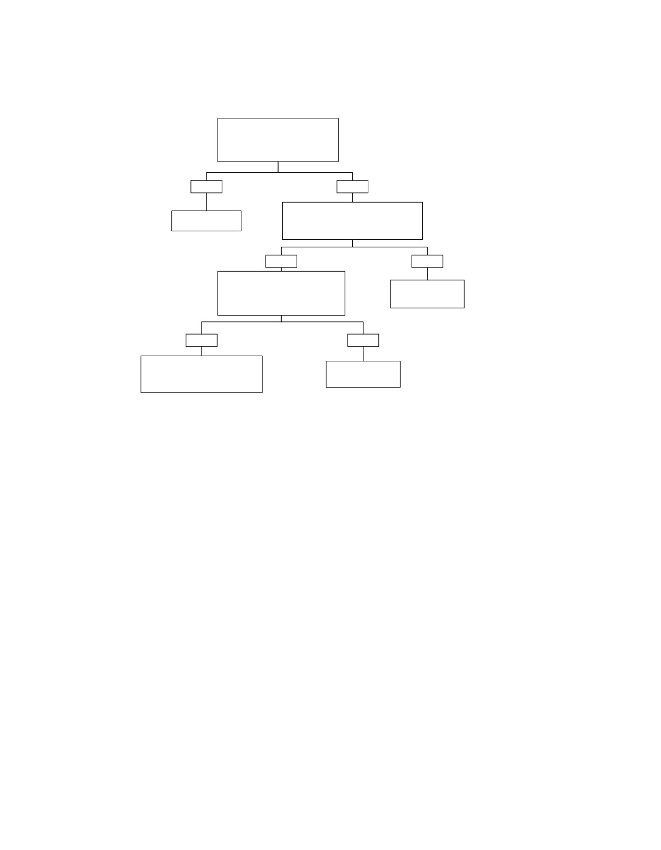
ABS Indicator Always On or Inoperative
Verify that the vehicle is equipped
with ABS and has the appropriate
Speedometer. Check for DTCs.
Any ABS DTCs present?
YES
NO
Perform a WOW test. Refer to 2.3
Refer to appropriate
Speedometer Self Diagnostics.
Diagnostic table.
Does the ABS lamp function properly during
the WOW test?
YES
NO
Inspect (LGN/V) between terminal “9” of
connector [166B] and terminal “2” of
Refer to 2.3
connector [108B] (connector [39B] on
Speedometer Self
FLHR) for an open.
Diagnostics.
Open condition present?
YES
NO
Repair open in (LGN/V) between
terminal “9” of connector [166B] and
Replace ABS Module.
terminal “2” of connector [108B]
(connector [39B] on FLHR).
fc01557_en
6-16 2008 Touring Diagnostics: ABS
HOME
DTC C0562
6.6
DTC C0562: DEVICE VOLTAGE LOW
Conditions for Clearing the DTC
The condition for the DTC is no longer present and the DTC
Circuit Description
has been cleared with either a "WOW" test or Digital Techni-
The ABS module monitors the voltage level available for system
cian.
operation. A low voltage condition prevents the system from
The ABS module automatically clears the historic DTC when
operating properly.
a current DTC is not detected in 50 consecutive drive cycles.
Conditions for Running the DTC
Diagnostic Tips
Ignition voltage is greater than 6.5V and the vehicle speed is
The following conditions are possible causes for this fault:
above 5 MPH (8 km/h).
•
Charging system malfunction.
Conditions for Setting the DTC
•
Excessive battery draw and/or extended idling in heavy
One of the following conditions exists for at least 0.72 seconds:
traffic.
•
During initialization or when the system is active the
•
A weak battery.
system voltage is below 9.0V.
•
A faulty system ground.
•
The system voltage drops below 10.5V with the system
enabled and the pump not running.
Diagnostic Notes
•
The ignition voltage is below 8.7V.
Each reference number below correlates to a circled number
on the flow chart(s).
•
Battery voltage is below 8.7V with vehicle speed above
5 MPH (8 km/h) and engine speed above 500 RPM.
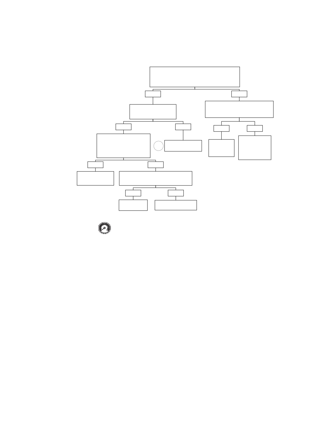
1. The ignition circuit between wire harness connector [166B]
and ABS connector [166A] consists of all the circuitry back
Action Taken When the DTC Sets
to and including the Ignition Switch.
•
ABS is disabled.
•
The ABS indicator is illuminated.
2008 Touring Diagnostics: ABS 6-17
HOME
em00159
MAXIFUSE
Voltage
40 Amp
Regulator
BK
1
1
BK
[5B]
[77B] [77A]
Electronic
B A
Hydraulic
Control Unit (ECU)
BK
Control Unit
R
R
(HCU)
1
1
Pump motor supply
Pump
M
Motor
2
2
Pump motor ground
Battery
IGN
I
A
R/BK
OFF
B
B
R
A
C
1E
4A
[64-2]
ACC
Ignition
ABS Motor
Ignition
Fuse
Fuse
Switch
[33A]
[33B]
15 Amp
30 Amp
1F
4B
R/V
R/V
20
20
Battery (Motor)
See appendix B
main harness
GY
R/V
10
10
Battery
page 1 of 3
GY
19
19
Ignition
See appendix B
main harness
LGN/V
page 1 of 3
Tachometer
Serial data
2
2
LGN/V
2
2
LGN/V
LGN/V
9
9
Serial data
[108A]
[108B]
[20A] [20B]
BK
1
1
Ground
See appendix B
main harness
BK
11
11
Ground (Motor)
page 1 of 3
[GND 1A]
[166B] [166A]
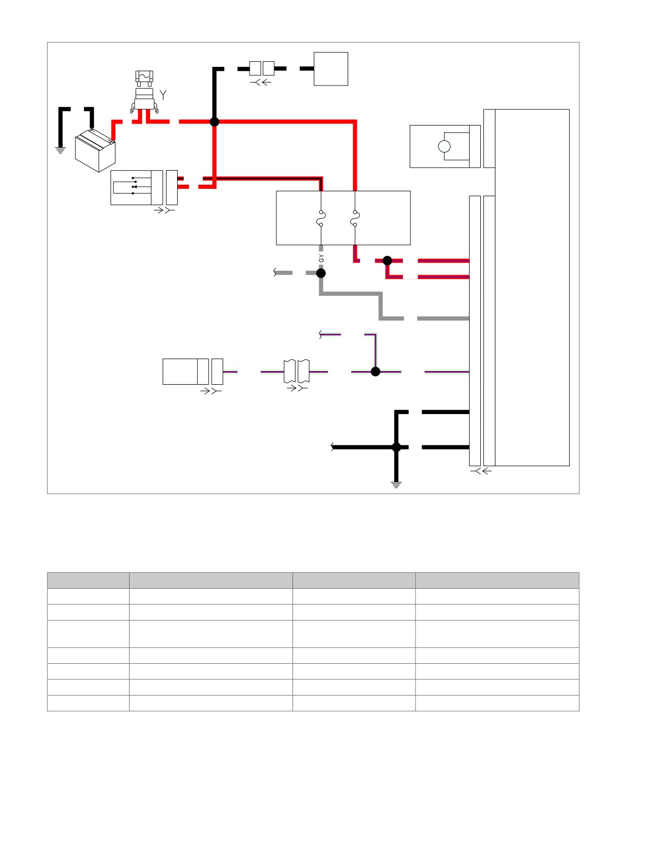
Figure 6-12. ABS Power and Ground Schematic
Table 6-4. FLHX, FLHT/C/U Connector Locations
NO.
DESCRIPTION
TYPE
LOCATION
[5]
MAXIFUSE
2-place Packard
Under left side cover
[20]
Console harness
16-place Molex
Under seat
[33]
Ignition Switch
3-place Packard
Inner fairing
- under radio
(front of
Ignition Switch housing)
[64-2]
Fuse block
Packard
Under left side cover
[77]
Voltage regulator
2-place Lyall
Bottom of voltage regulator (right side)
[108]
T
achometer
12-place Packard
Inner fairing (back of tachometer)
[166]
ABS module
20-place Molex
Under right side cover
6-18 2008 Touring Diagnostics: ABS
HOME
Device Voltage Low: DTC C0562
Install Breakout Box (HD-48642). Turn the Ignition Switch
to the IGNITION position. Using a DVOM test for voltage
from terminal “20” to ground and terminal “10” to ground
Is the voltage above 10.5V on both terminals?
YES
NO
Test battery circuit terminals “10” and “20”
Test the ignition circuit
of breakout box for high resistance.
terminal “19” for voltage.
High resistance present?
Is voltage above 10.5V?
YES
NO
YES
NO
Test the ground circuits at
Repair Battery and
terminals “1” and “11” for high
Repair high
Repair high resistance
charging system.
resistance or an open.
1
resistance in
in ignition circuit.
Refer to Section 1.7
Is high resistance or open
appropriate
CHARGING
present?
circuit.
SYSTEM.
YES
NO
Repair high resistance
Clear the DTC. Operate the system within
or open condition on
Conditions for Running the DTC.
ground circuits.
Does the DTC reset?
YES
NO
Replace ABS
Refer to Diagnostic Tips.
Module.
Clear DTCs using speedometer self diagnostics.
See 2.3 SPEEDOMETER SELF DIAGNOSTICS.
Confirm proper operation with no check engine
fc01558_en
lamp.
2008 Touring Diagnostics: ABS 6-19
HOME
DTC C0563
6.7
DTC C0563: DEVICE VOLTAGE HIGH
Action Taken When the DTC Sets
•
ABS is disabled.
Circuit Description
•
The ABS indicator is illuminated.
The ABS module monitors the system voltage level. If the
voltage level is too high, damage may result to the system.
Conditions for Clearing the DTC
When the ABS module detects a high voltage condition, it dis-
ables the ABS.
The condition for the DTC is no longer present and the DTC
has been cleared with either a "WOW" test or Digital Techni-
Conditions for Running the DTC
cian.
Ignition voltage is greater than 6.5V.
The ABS module automatically clears the historic DTC when
a current DTC is not detected in 50 consecutive drive cycles.
Conditions for Setting the DTC
One of the following conditions exists for at least 0.72 seconds:
Diagnostic Tips
•
When the system is active the system voltage is above
This fault could be caused by an overcharging condition with
18.0V.
either the vehicle's charging system or an external charging
system.
•
The ignition voltage is above 18.0V.
em00159
MAXIFUSE
Voltage
40 Amp
Regulator
BK
1
1
BK
[5B]
[77B] [77A]
Electronic
B A
Hydraulic
Control Unit (ECU)
BK
Control Unit
R
R
(HCU)
1
1
Pump motor supply
Pump
M
Motor
2
2
Pump motor ground
Battery
IGN
I
A
R/BK
OFF
B
B
R
A
C
1E
4A
[64-2]
ACC
Ignition
ABS Motor
Ignition
Fuse
Fuse
Switch
[33A]
[33B]
15 Amp
30 Amp
1F
4B
R/V
R/V
20
20
Battery (Motor)
See appendix B
main harness
GY
R/V
10
10
Battery
page 1 of 3
GY
19
19
Ignition
See appendix B
main harness
LGN/V
page 1 of 3
Tachometer
Serial data
2
2
LGN/V
2
2
LGN/V
LGN/V
9
9
Serial data
[108A]
[108B]
[20A] [20B]
BK
1
1
Ground
See appendix B
main harness
BK
11
11
Ground (Motor)
page 1 of 3
[GND 1A]
[166B] [166A]
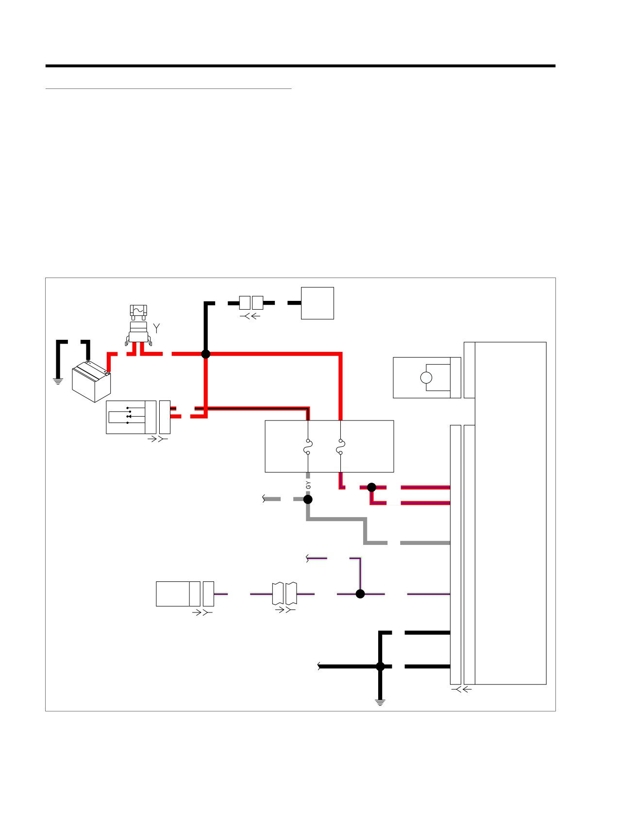
Figure 6-13. ABS Power and Ground Schematic
6-20 2008 Touring Diagnostics: ABS