Harley Davidson 2018 softail models. Service manual - page 42
See Figure 1. A dual TPS is integrated into the TCA, mounted to the induction module.
Within the TCA, a set of potentiometers are designated as TPS (TPS1 and TPS2). The ECM drives the motor in the TCA to
open and close the throttle plate based on the signals from the twist grip sensor. The TPS (TPS1 and TPS2) send signals
back to the ECM based on throttle plate position to verify the throttle plate movement.
The ECM supplies a 5.0V signal from terminal [78-2] terminal 9 to TPS1 and [78-3] terminal 18 to TPS2. The signals from
TPS1 and TPS2 are sent back to the ECM [78-3] terminals 13 and 14 and vary in voltage according to actual throttle plate
position.
The two TP sensors work opposite each other. When one sensor reads high, the other reads low. The sum of TPS1 and
TPS2 signals should measure around 5.0V.
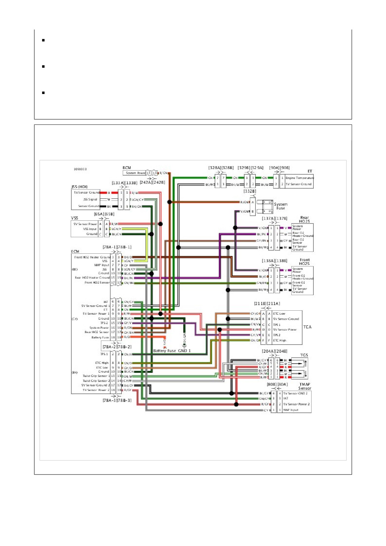
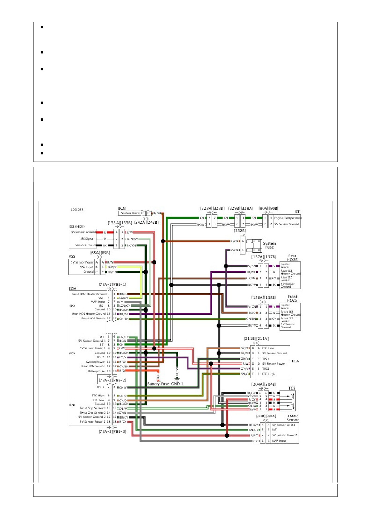
See Figure 2 for TCA (TPS1 and TPS2) circuitry diagram. Refer to Table 1 for DTCs associated with TPS1 and TPS2 of
the TCA.
Table 1. Code Description
DTC
DESCRIPTION
P0120
TPS1 range error
P0122
TPS1 low/open
P0123
TPS1 high
P0220
TPS2 range error
P0222
TPS2 low/open
P0223
TPS2 high
1
Front knock sensor [315]
2
Front ACR [203F]
3
Rear knock sensor [316]
4
Rear ACR [203R]
5
Rear injector [85]
6
TMAP [80]
7
Ignition coil [83]
8
Throttle control [211]
9
Front injector [84]
Figure 1. Engine
NOTE
The TGS, JSS, TCA and VSS sensors are connected to the same reference line (5V reference). If the reference line
goes to ground or open, multiple codes will be set (DTC P0122, P0123, P0502, P0503, P1501, P1502, P2101, P2102,
P2103, 2122, 2123, P2127, P2128). Start with the trouble code having the highest priority DTC. Refer to Diagnostics.
Check for the following conditions:
Poor connection: Inspect ECM harness connector [78B-1], [78B-2] and [78-B-3] for backed out terminals, improper
mating, inoperative locks, improperly formed or damaged terminals, poor terminal-to-wire connection and damaged
harness.
Perform Wiggle Test to locate intermittents: If connections and harness check out OK, monitor TPS voltage using a
multimeter while moving related connectors and wiring harness. If the failure is induced, the TPS voltage will change.
An intermittent may be caused by poor connection, rubbed through wire insulation or an inoperative wire within the wire
insulation.
Diagnostic Tips
A faulty sensor can negatively affect the signal voltage of the other sensors sharing the same 5V reference. If the
wiring passes the following tests, disconnect one sensor at a time on the 5V reference and verify the DTC is still
present. Additional DTCs will be set as each sensor is disconnected, clear DTCs after this test. Be sure to perform this
test before replacing a component.
Connector Information
For additional information about the connectors in the following diagram(s) and diagnostic procedure(s), see General.
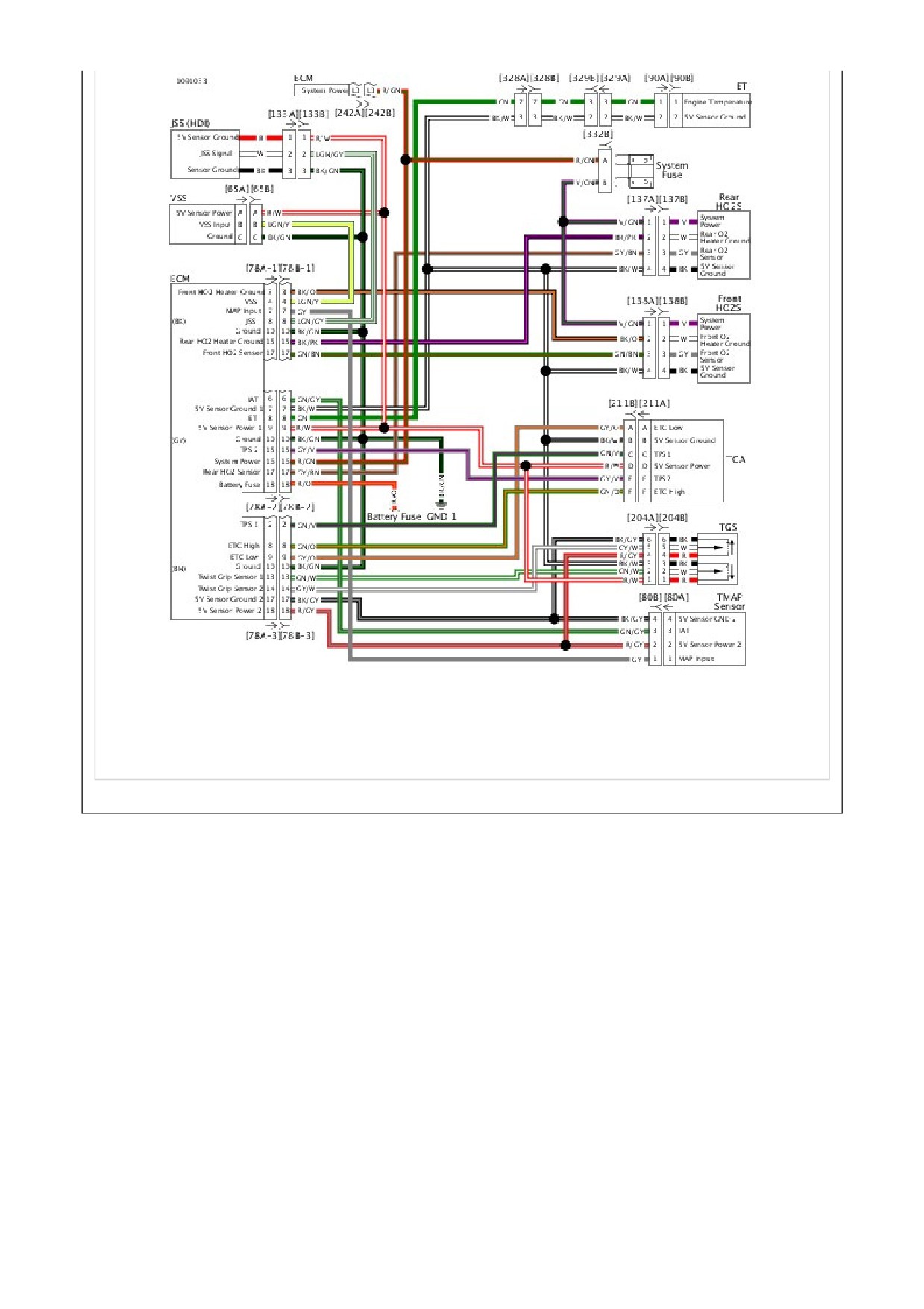
Figure 2. Sensor Circuit
Special Tools
Description
Part Number
Qty.
TEST CONNECTOR KIT
HD-41404
1
BREAKOUT BOX
HD-50390-1
1
ECM CABLE
HD-50390-4
1
ECM OVERLAY
HD-50390-4-P
1
Table 1. DTC P0120 Diagnostic Faults
POSSIBLE CAUSES
Open in sensor power circuit
Short to voltage in TPS-1 circuit
Open in TPS-1 circuit
Short to ground in TPS-1 circuit
Open sensor ground circuit
1. Sensor Power-1 Circuit Test
1. Turn IGN OFF.
2. Connect BREAKOUT BOX (Part Number:HD-50390-1) and ECM CABLE (Part Number:HD-50390-4) to
wiring harness [78B-1], [78B-2] and [78B-3], leaving ECM [78A-1], [78A-2] and [78A-3] disconnected. See
How To Use Diagnostic Tools.
3. Verify ECM OVERLAY (Part Number:HD-50390-4-P) is in position on BOB.
4. Disconnect TCA [211].
5. Using TEST CONNECTOR KIT (Part Number:HD-41404), test resistance between BOB [78-2] terminal 9 and
[211B] terminal D.
6. Is resistance less than 0.5 ohms?
a. Yes. Go to Test 2.
b. No. Repair open in (R/W) wire.
2. TPS-1 Circuit Shorted Test
1. Test continuity between BOB [78-2] terminal 9 and [78-3] terminal 2.
2. Is continuity present?
a. Yes. Repair short between (GN/V) and (R/W) wires.
b. No. Go to Test 3.
3. TPS-1 Circuit Continuity Test
1. Test resistance between BOB [78-3] terminal 2 and [211B] terminal C.
2. Is resistance less than 0.5 ohms?
a. Yes. Go to Test 4.
b. No. Repair open in (GN/V) wire.
4. TPS-1 Circuit Short to Ground Test
1. Test continuity between BOB [78-3] terminal 2 and ground.
2. Is continuity present?
a. Yes. Repair short to ground on (GN/V) wire.
b. No. Go to Test 5.
5. TPS-1 Circuit Short to Voltage Test
1. Turn IGN ON.
2. Test voltage between BOB [78-3] terminal 2 and ground.
3. Is voltage present?
a. Yes. Repair short to voltage on (GN/V) wire.
b. No. Go to Test 6.
6. Sensor Ground Continuity Test
1. Test resistance between BOB [78-2] terminal 7 and [211B] terminal B.
2. Is resistance less than 0.5 ohms?
a. Yes. Go to Test 7.
b. No. Repair open in (BK/W) wire.
7. TCA Test
1. Turn IGN OFF.
2. Connect [78A-1], [78A-2] and [78A-3] to BOB.
3. Connect [211].
4. Turn IGN ON.
5. Test voltage between BOB [78-2] terminal 7 and [78-3] terminal 2.
6. Is voltage between 0.4-4.8V?
a. Yes. Replace ECM.
b. No. Replace TCA.
Special Tools
Description
Part Number
Qty.
TEST CONNECTOR KIT
HD-41404
1
BREAKOUT BOX
HD-50390-1
1
ECM CABLE
HD-50390-4
1
ECM OVERLAY
HD-50390-4-P
1
Table 1. DTC P0122 Diagnostic Faults
POSSIBLE CAUSES
Short to ground in TPS-1 Circuit
Open in sensor power circuit
1. TCA Sensor-1 Circuit Test
1. Turn IGN OFF.
2. Connect BREAKOUT BOX (Part Number:HD-50390-1) and ECM CABLE (Part Number:HD-50390-4)
between wiring harness [78B-1], [78B-2] and [78B-3] and ECM [78A-1], [78A-2] and [78A-3]. See How To Use
Diagnostic Tools.
3. Verify ECM OVERLAY (Part Number:HD-50390-4-P) is in position on BOB.
4. Turn IGN ON.
5. Using TEST CONNECTOR KIT (Part Number:HD-41404), test voltage between BOB [78-3] terminal 2 and
[78-2] terminal 7.
6. Is voltage greater than 0.2V?
a. Yes. Go to Test 2.
b. No. Go to Test 4.
2. TCA Sensor-1 Circuit Short to Ground Test
1. Turn IGN OFF.
2. Disconnect ECM [78A-1], [78A-2] and [78A-3] from BOB.
3. Disconnect TCA [211].
4. Test continuity between BOB [78-3] terminal 2 and ground.
5. Is continuity present?
a. Yes. Repair short to ground in (GN/V) wire.
b. No. Go to Test 3.
3. TCA Power-1 Circuit Open Test
1. Test resistance between BOB [78-2] terminal 9 and [211] terminal 5.

2. Is resistance less than 0.5 ohms?
a. Yes. Replace TCA.
b. No. Repair open in (R/W) wire.
4. TCA Sensor Test
1. Turn IGN OFF.
2. Disconnect TCA [211].
3. Test voltage between BOB [78-2] terminal 9 and ground.
4. Is voltage greater than 4V?
a. Yes. Replace TCA.
b. No. Go to Test 5.
5. ECM Test
1. Disconnect ECM [78A-1], [78A-2] and [78A-3] from BOB.
2. Test continuity between BOB [78-3] terminal 2 and ground.
3. Is continuity present?
a. Yes. Repair short to ground in (GN/V) wire.
b. No. Replace ECM.
Special Tools
Description
Part Number
Qty.
TEST CONNECTOR KIT
HD-41404
1
BREAKOUT BOX
HD-50390-1
1
ECM CABLE
HD-50390-4
1
ECM OVERLAY
HD-50390-4-P
1
Table 1. DTC P0123 Diagnostic Faults
POSSIBLE CAUSES
Open in TPS-1 circuit
Short to voltage in TPS-1 circuit
Short to voltage in sensor power circuit
Open in sensor ground circuit
1. TPS-1 Voltage Test
1. Turn IGN OFF.
2. Connect BREAKOUT BOX (Part Number:HD-50390-1) and ECM CABLE (Part Number:HD-50390-4)
between wiring harness [78B-1], [78B-2] and [78B-3], and ECM [78A-1], [78A-2] and [78A-3]. See How To
Use Diagnostic Tools.
3. Verify ECM OVERLAY (Part Number:HD-50390-4-P) is in position on BOB.
4. Turn IGN ON.
5. Using TEST CONNECTOR KIT (Part Number:HD-41404), test voltage between BOB [78-3] terminal 2 and
[78-2] terminal 7.
6. Is voltage less than 4.8V?
a. Yes. Go to Test 8.
b. No. Go to Test 2.
2. TPS-1 Circuit Test
1. Turn IGN OFF.
2. Disconnect TCA [211].
3. Turn IGN ON.
4. Test voltage between [211B] terminal C and ground.
5. Is voltage between 4-5.25V?
a. Yes. Go to Test 3.
b. No, less than 4V. Repair open in (GN/V) wire.
c. No, greater than 5.25V. Repair short to voltage in (GN/V) wire.

3. Sensor Power Circuit Test
1. Test voltage between [211B] terminal D and ground.
2. Is voltage less than 5.25V?
a. Yes. Go to Test 4.
b. No. Repair short to voltage in (R/W) wire.
4. TCA Test
1. Jumper [211B] terminals C and B.
2. Test voltage between BOB [78-3] terminal 2 and [78-2] terminal 7.
3. Is voltage greater than 1.0V?
a. Yes. Go to Test 5.
b. No. Replace TCA.
5. Sensor Ground Test
1. Turn IGN OFF.
2. Test resistance between [211B] terminal B and ground.
3. Is resistance less than 2 ohms?
a. Yes. Go to Test 6.
b. No. Go to Test 7.
6. Sensor Ground Circuit Shorted Test
1. Test continuity between [211B] terminals D and C.
2. Is continuity present?
a. Yes. Repair short between (GN/V) and (R/W) wires.
b. No. Replace ECM.
7. Sensor Ground Circuit Test
1. Disconnect ECM [78A-1], [78A-2] and [78A-3].
2. Test resistance between [211B] terminal B and BOB [78-2] terminal 7.
3. Is resistance less than 0.5 ohms?
a. Yes. Replace ECM.
b. No. Repair open in (BK/W) wire.
8. TPS-1 Circuit Function Test
1. Disconnect TCA [211].
2. Test voltage between [211B] terminal C and ground.
3. Is voltage between 2-5.25V?
a. Yes. Go to Test 9.

b. No. Less than 2V. Repair open in (GN/V) wire.
c. No. Greater than 5.25V. Repair short to voltage on (GN/V) wire.
9. Sensor Power Short to Voltage Test
1. Test voltage between [211B] terminal D and ground.
2. Is voltage less than 5.25V?
a. Yes. Go to Test 10.
b. No. Repair short to voltage on (R/W) wire.
10. Ground Circuit Open Test
1. Turn IGN OFF.
2. Disconnect ECM [78A-1], [78A-2] and [78A-3].
3. Test resistance between [211B] terminal B and BOB [78-2] terminal 7.
4. Is resistance less than 0.5 ohms?
a. Yes. Go to Test 11.
b. No. Repair open in (BK/W) wire.
11. TPS-1 Continuity Test
1. Test resistance between [211B] terminal C and BOB [78-3] terminal 2.
2. Is resistance less than 0.5 ohms?
a. Yes. Replace TCA.
b. No. Repair open in (GN/V) wire.
Special Tools
Description
Part Number
Qty.
TEST CONNECTOR KIT
HD-41404
1
BREAKOUT BOX
HD-50390-1
1
ECM CABLE
HD-50390-4
1
ECM OVERLAY
HD-50390-4-P
1
Table 1. DTC P0220 Diagnostic Faults
POSSIBLE CAUSES
Open in sensor power circuit
Short to voltage in sensor power circuit
Open in TPS-2 circuit
Short to voltage in TPS-2 circuit
Short to ground in TPS-2 circuit
Open in sensor ground circuit
1. Sensor Power-1 Circuit Test
1. Turn IGN OFF.
2. Connect BREAKOUT BOX (Part Number:HD-50390-1) and ECM CABLE (Part Number:HD-50390-4) to
wiring harness [78B-1], [78B-2] and [78B-3], leaving ECM [78A-1], [78A-2] and [78A-3] disconnected. See
How To Use Diagnostic Tools.
3. Verify ECM OVERLAY (Part Number:HD-50390-4-P) is in position on BOB.
4. Disconnect TCA [211].
5. Using TEST CONNECTOR KIT (Part Number:HD-41404), test resistance between BOB [78-2] terminal 9 and
[211] terminal 5.
6. Is resistance less than 0.5 ohms?
a. Yes. Go to Test 2.
b. No. Repair open in (R/W) wire.
2. Sensor Power-1 Short to Voltage Test
1. Turn IGN ON.
2. Test voltage between BOB [78-2] terminal 9 and ground.
3. Is battery voltage present?
a. Yes. Repair short to voltage (R/W) wire.
b. No. Go to Test 3.
3. TPS-2 Circuit Shorted Test
1. Turn IGN OFF.
2. Test continuity between BOB [78-2] terminals 9 and 15.
3. Is continuity present?
a. Yes. Repair short between (R/W) and (GY/V) wires.
b. No. Go to Test 4.
4. TPS-2 Circuit Resistance Test
1. Test resistance between BOB [78-2] terminal 15 and [211B] terminal E.
2. Is resistance less than 0.5 ohms?
a. Yes. Go to Test 5.
b. No. Repair open in (GY/V) wire.
5. TPS-1 Circuit Short to Ground Test
1. Test continuity between BOB [78-2] terminal 15 and ground.
2. Is continuity present?
a. Yes. Repair short to ground on (GY/V) wire.
b. No. Go to Test 6.
6. TPS-1 Circuit Short to Voltage Test
1. Turn IGN ON.
2. Test voltage between BOB [78-2] terminal 15 and ground.
3. Is voltage present?
a. Yes. Repair short to voltage on (GY/V) wire.
b. No. Go to Test 7.
7. Sensor Ground Resistance Test
1. Turn IGN OFF.
2. Test resistance between BOB [78-2] terminal 7 and [211B] terminal B.
3. Is resistance less than 0.5 ohms?
a. Yes. Go to Test 8.
b. No. Repair open in (BK/W) wire.
8. TCA Test
1. Connect [78A-1], [78A-2] and [78A-3] to BOB.
2. Connect [211].
3. Turn IGN ON.
4. Test voltage between BOB [78-2] terminals 15 and 7.
5. Is voltage between 0.4-4.8V?
a. Yes. Replace ECM.
b. No. Replace TCA.
Special Tools
Description
Part Number
Qty.
TEST CONNECTOR KIT
HD-41404
1
BREAKOUT BOX
HD-50390-1
1
ECM CABLE
HD-50390-4
1
ECM OVERLAY
HD-50390-4-P
1
Table 1. DTC P0222 Diagnostic Faults
POSSIBLE CAUSES
Open in sensor power circuit
Short to ground in TPS-2 circuit
1. TCA Sensor-2 Circuit Test
1. Turn IGN OFF.
2. Connect BREAKOUT BOX (Part Number:HD-50390-1) and ECM CABLE (Part Number:HD-50390-4)
between wiring harness [78B-1], [78B-2] and [78B-3], and ECM [78A-1], [78A-2] and [78A-3]. See How To
Use Diagnostic Tools.
3. Verify ECM OVERLAY (Part Number:HD-50390-4-P) is in position on BOB.
4. Turn IGN ON.
5. Using TEST CONNECTOR KIT (Part Number:HD-41404), test voltage between BOB [78-2] terminals 15 and
7.
6. Is voltage greater than 0.2V?
a. Yes. Go to Test 2.
b. No. Go to Test 4.
2. TCA Sensor-2 Circuit Short to Ground Test
1. Turn IGN OFF.
2. Disconnect [78A-1], [78A-2] and [78A-3] from BOB.
3. Disconnect TCA [211].
4. Test continuity between BOB [78-2] terminal 15 and ground.
5. Is continuity present?
a. Yes. Repair short to ground in (GY/V) wire.
b. No. Go to Test 3.
3. TCA Power-1 Circuit Open Test
1. Test resistance between BOB [78-2] terminal 9 and [211] terminal 5.
2. Is resistance less than 0.5 ohms?
a. Yes. Replace TCA.
b. No. Repair open in (R/W) wire.
4. TCA 5V Reference Circuit Short to Ground Test
1. Turn IGN OFF.
2. Disconnect [211].
3. Turn IGN ON.
4. Test voltage between BOB [78-2] terminal 9 and ground.
5. Is voltage greater than 4V?
a. Yes. Replace TCA.
b. No. Go to Test 5.
5. ECM Test
1. Turn IGN OFF.
2. Disconnect [78A] from BOB.
3. Test resistance between BOB [78-2] terminal 15 and ground.
4. Is resistance greater than 0.5 ohms?
a. Yes. Repair short to ground in (GY/V) wire.
b. No. Replace ECM.
Special Tools
Description
Part Number
Qty.
TEST CONNECTOR KIT
HD-41404
1
BREAKOUT BOX
HD-50390-1
1
ECM CABLE
HD-50390-4
1
ECM OVERLAY
HD-50390-4-P
1
Table 1. DTC P0223 Diagnostic Faults
POSSIBLE CAUSES
Open in sensor power circuit
Short to voltage in sensor power circuit
Open in TPS-2 circuit
Short to voltage in TPS-2 circuit
Short to ground in TPS-2 circuit
Open in sensor ground circuit
1. TPS-2 Voltage Test
1. Turn IGN OFF.
2. Connect BREAKOUT BOX (Part Number:HD-50390-1) and ECM CABLE (Part Number:HD-50390-4) to
wiring harness [78B-1], [78B-2] and [78B-3], and ECM [78A-1], [78A-2] and [78A-3]. See How To Use
Diagnostic Tools.
3. Verify ECM OVERLAY (Part Number:HD-50390-4-P) is in position on BOB.
4. Turn IGN ON.
5. Using TEST CONNECTOR KIT (Part Number:HD-41404), test voltage between BOB [78-2] terminals 15 and
7.
6. Is voltage less than 4.8V?
a. Yes. Go to Test 7.
b. No. Go to Test 2.
2. TPS-2 Circuit Test
1. Disconnect TCA [211].
2. Test voltage between [211B] terminal E and ground.
3. Is voltage less than 0.2V?
a. Yes. Go to Test 3.
b. No. Go to Test 5.
3. Sensor Power Circuit Test
1. Test voltage between [211B] terminal D and ground.
2. Is voltage less than 5.25V?
a. Yes. Go to Test 4.
b. No. Repair short to voltage in (R/W) wire.
4. Sensor Ground Test
1. Turn IGN OFF.
2. Test resistance between [211B] terminal B and ground.
3. Is resistance less than 2 ohms?
a. Yes. Replace TCA.
b. No. Go to Test 6.
5. Shorted 5V Circuit Test
1. Disconnect [78A-1], [78A-2] and [78A-3].
2. Test continuity between [211B] terminals E and D.
3. Is continuity present?
a. Yes. Repair short between (GY/V) and (R/W) wires.
b. No. Replace ECM.
6. Sensor Ground Circuit Test
1. Test resistance between [211B] terminal B and BOB [78-2] terminal 7.
2. Is resistance less than 0.5 ohms?
a. Yes. Replace ECM.
b. No. Repair open in (BK/W) wire.
7. TPS-2 Circuit Test
1. Disconnect [78A-1], [78A-2] and [78A-3].
2. Disconnect TCA [211].
3. Turn IGN ON.
4. Test voltage between [211B] terminal E and ground.
5. Is voltage less than 1.0V?
a. Yes. Go to Test 8.
b. No. Repair short to voltage on (GY/V) wire.
8. Sensor Short to Voltage Test
1. Test voltage between [211B] terminal D and ground.
2. Is voltage less than 5.25V?
a. Yes. Go to Test 9.
b. No. Repair short to voltage on (R/W) wire.
9. Ground Circuit Open Test
1. Turn IGN OFF.
2. Disconnect [78A-1], [78A-2] and [78A-3].
3. Test resistance between [211B] terminal B and BOB [78-2] terminal 7.
4. Is resistance less than 0.5 ohms?
a. Yes. Replace TCA.
b. No. Repair open in (BK/W) wire.
See Figure 1. The ECM supplies and monitors a voltage signal from [78-2] terminal 8 to one side of the ET sensor. The
other side of the ET sensor is connected to a common sensor ground. The ground is also connected to the ECM [78-2]
terminal 7.
The ET sensor is a thermistor device. At a specific temperature it will have a specific resistance across its terminals. As
this resistance varies, so does the voltage on ECM [78-2] terminal 8.
At high temperatures, the resistance of the sensor is very low. This lowers the signal voltage on ECM [78-2] terminal 8.
At low temperatures, the resistance is very high. This allows the voltage to rise close to 5V.
The ECM monitors this voltage to compensate for various operating conditions.
Table 1. Code Description
DTC
DESCRIPTION
P0117
ET sensor shorted low
P0118
ET sensor high/open
1
USB caddy interconnect [329]
2
USB [264]
3
Fuel pump [141]
4
ET sensor [90]
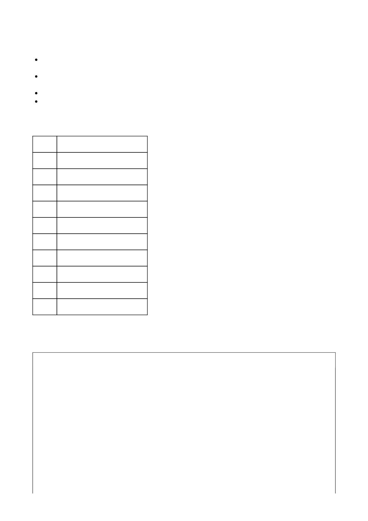
Figure 1. Under Fuel Tank Left Side
Diagnostic Tips
Once the engine is started, the temperature should rise steadily to operating temperature.
An intermittent may be caused by a poor connection, rubbed through wire insulation or an inoperative wire inside the
insulation.
Check the following conditions:
Poor connection: Inspect ECM harness connector [78-1], [78-2] and [78-3] for backed out terminals, improper
mating, inoperative locks, improperly formed or damaged terminals, poor terminal-to-wire connection and
damaged harness.
Perform Wiggle Test to locate intermittents: If connections and harness check out OK, use a multimeter to
check the engine temperature reading while moving related connectors and wiring harness. If the failure is
induced, the engine temperature display will change.
Shifted sensor resistance value: Measure ET and IAT sensor temperatures with a cool engine. The sensor
temperatures should be within 5.6 °C (10 °F) of each other. If the two sensors are not within the specified range
replace the inaccurate sensor.
Connector Information
For additional information about the connectors in the following diagram(s) and diagnostic procedure(s), see General.
Figure 2. Sensor Circuit
Special Tools
Description
Part Number
Qty.
TEST CONNECTOR KIT
HD-41404
1
BREAKOUT BOX
HD-50390-1
1
ECM CABLE
HD-50390-4
1
ECM OVERLAY
HD-50390-4-P
1
Table 1. DTC P0117 Diagnostic Faults
POSSIBLE CAUSES
ET sensor malfunction
Short to ground in 5V reference circuit
1. ET Sensor Test
NOTE
Vehicle and sensor must be at ambient room temperature before starting diagnostic test.
1. Turn IGN OFF.
2. Disconnect ET sensor [90].
3. Using TEST CONNECTOR KIT (Part Number:HD-41404), test resistance between [90B] terminals 1 and 2.
4. Is resistance between 900-10,000 ohms?
a. Yes. Go to Test 2.
b. No. Replace ET sensor.
2. ET Sensor Signal Wire Shorted to Ground Test
1. Test resistance between [90A] terminal 1 (GN) wire and ground.
2. Is resistance less than 1 ohm?
a. Yes. Repair short to ground in (GN) wire.
b. No. Go to Test 3.
3. ET Sensor Signal Wire Shorted to Sensor Ground Test
1. Connect BREAKOUT BOX (Part Number:HD-50390-1) and ECM CABLE (Part Number:HD-50390-4) to
wiring harness [78B-1], [78B-2] and [78B-3], leaving ECM [78A-1], [78A-2] and [78A-3] disconnected. See
How To Use Diagnostic Tools.
2. Verify ECM OVERLAY (Part Number:HD-50390-4-P) is in position on BOB.
3. Test continuity between BOB [78-2] terminals 8 and 7.
4. Is continuity present?
a. Yes. Repair short between [90A] terminals 1 (GN) wire and 2 (BK/W) wire.
b. No. Replace ECM.
Special Tools
Description
Part Number
Qty.
TEST CONNECTOR KIT
HD-41404
1
BREAKOUT BOX
HD-50390-1
1
ECM CABLE
HD-50390-4
1
ECM OVERLAY
HD-50390-4-P
1
Table 1. DTC P0118 Diagnostic Faults
POSSIBLE CAUSES
ET sensor malfunction
Open or short to voltage in 5V reference circuit
1. ET Signal Voltage Test
1. Turn IGN OFF.
2. Disconnect ET sensor [90].
3. Using TEST CONNECTOR KIT (Part Number:HD-41404), test voltage between [90A] terminal 1 (GN) wire
and ground.
4. Turn IGN ON.
5. Is voltage greater than 6V?
a. Yes. Repair short to voltage on (GN) wire.
b. No.
2. ET Sensor Signal Wire Open Test
1. Turn IGN OFF.
2. Connect BREAKOUT BOX (Part Number:HD-50390-1) and ECM CABLE (Part Number:HD-50390-4) to
wiring harness [78B-1], [78B-2] and [78B-3], leaving ECM [78A-1], [78A-2] and [78A-3] disconnected. See
How To Use Diagnostic Tools.
3. Verify ECM OVERLAY (Part Number:HD-50390-4-P) is in position on BOB.
4. Test resistance between [90A] terminal 1 (GN) wire and BOB [78-2] terminal 8.
5. Is resistance less than 0.5 ohms?
a. Yes.
b. No. Repair open in (GN) wire.
3. ET Sensor Open Ground Wire Test
1. Test resistance between [90A] terminal 2 (BK/W) wire and BOB [78-2] terminal 7.
2. Is resistance less than 0.5 ohms?
a. Yes.
b. No. Repair open in (BK/W) wire.
4. ET Sensor Signal Wire Shorted to Sensor Power Test
1. Test continuity between BOB [78-2] terminals 8 and 9.
2. Is continuity present?
a. Yes. Repair short between (GN) and (R/W) wires.
b. No.
5. ET Sensor Test
1. Connect [90].
2. Test continuity between BOB [78-2] terminals 8 and 7.
3. Is continuity present?
a. Yes. Replace ECM.
b. No. Replace ET sensor.
The HO2S provides a signal to the ECM which indicates whether the engine is running rich or lean.
A P0131 (front) or P0151 (rear) is set when the ECM detects an excessively lean condition for a specified length of
time. DTCs may also set if HO2S fails.
A P0132 (front) or P0152 (rear) is set when the ECM detects an excessively rich condition for a specified length of
time. This can be caused by oil contamination or fuel injector malfunctions. DTCs may also set if HO2S fails.
A P0134 (front) or a P0154 (rear) is set when the sensor circuit is open or too cold to respond.
When the air/fuel mixture is ideal, approximately 14.6 parts air to 1 part fuel, the voltage will be approximately 0.45V
when measuring across the sensor.
Table 1. Code Description
DTC
DESCRIPTION
P0031
Front HO2S low/open
P0032
Front HO2S shorted high
P0051
Rear HO2S low/open
P0052
Rear HO2S shorted high
P0131
O2 sensor low/engine lean (front)
P0132
Engine running rich (front)
P0134
O2 sensor high/open (front)
P0151
O2 sensor low/engine lean (rear)
P0152
Engine running rich (rear)
P0154
O2 sensor high/open (rear)
The heater portion of the HO2S is powered by the BCM. The front and rear HO2S heaters have separate control circuits
monitored by the ECM.
Diagnostic Tips
The ECM requires a HO2S fault be present for three drive cycles before it sets a code. After clearing codes, operate
the vehicle for three drive cycles before checking for codes.
The heater circuits in the HO2S are powered from the system power circuit. This circuit voltage is supplied by the BCM
through the system power fuse. Any short causing the fuse to open will cause the ECM to set DTC P0031 and P0051.
If these codes are present with an open fuse, the fault is a short to ground somewhere in the circuit or the
components.
The multimeter displays the signal from the HO2S in Volts. This voltage will have an average value tending towards
lean, rich or ideal value depending on operating temperature of the engine, engine speed and throttle position. An
open/short to voltage or short to ground in the (GN/BN) wire (front) and (GY/BN) wire (rear) will cause the engine to
run rich (short to ground) or lean (short to voltage) until the fault is detected. Once fault is detected, vehicle will run in
open loop.
Check for the following conditions:
Poor connection: Inspect the ECM [78-1], [78-2] and [78-3], fuel injector [84, 85] and HO2S [137, 138] connectors
for backed out terminals, improper mating, inoperative locks, improperly formed or damaged terminals, poor
terminal-to-wire connection and damaged harnesses.
Dirty/stuck open injectors: The vehicle may run lean (dirty/clogged injectors) or rich (stuck open injectors) if there
are injector problems. This could also cause poor fuel economy and performance.
Leaking injectors: This causes fuel imbalance and poor idle quality due to different air/fuel ratios in each cylinder.
To check for leaky injectors, first remove the air box and air filter. Then, with the throttle wide open, turn IGN ON
for 2 seconds and then OFF for 2 seconds five consecutive times. Replace the fuel injector if there is any evidence
of raw fuel in the bores. See Fuel Injectors in the service manual.
Loose HO2S: If an HO2S is loose, engine performance may be affected. This could also show up as a slow
changing HO2S voltage.
Loose/leaking exhaust: This can cause a poor ground connection for the sensor or allow fresh air into the
exhaust system. If fresh air enters exhaust system, the HO2S will read a lean condition, causing the system to go
rich.
Engine misfire: See Description and Operation.
Intake leaks: See the service manual.
Connector Information
For additional information about the connectors in the following diagram(s) and diagnostic procedure(s), see General.
Figure 1. Sensor Circuit
Special Tools
Description
Part Number
Qty.
TEST CONNECTOR KIT
HD-41404
1
BREAKOUT BOX
HD-50390-1
1
ECM CABLE
HD-50390-4
1
ECM OVERLAY
HD-50390-4-P
1
Table 1. DTC P0031 Diagnostic Faults
POSSIBLE CAUSES
Open or short to ground on front HO2S circuit
Open in sensor power circuit
1. Front HO2S Voltage Test
1. Turn IGN OFF.
2. Disconnect front HO2S [138].
3. Turn IGN ON.
4. Using TEST CONNECTOR KIT (Part Number:HD-41404), test voltage between [138A] terminal 1 (V/GN) wire
and ground.
5. Is battery voltage present?
a. Yes. Go to Test 2.
b. No. Repair open in (V/GN) wire.
2. Open Ground Test
1. Turn IGN OFF.
2. Connect BREAKOUT BOX (Part Number:HD-50390-1) and ECM CABLE (Part Number:HD-50390-4) to
wiring harness [78B-1], [78B-2] and [78B-3], leaving ECM [78A-1], [78A-2] and [78A-3] disconnected. See
How To Use Diagnostic Tools.
3. Verify ECM OVERLAY (Part Number:HD-50390-4-P) is in position on BOB.
4. Test resistance between BOB [78-1] terminal 3 and [138A] terminal 2 (BK/O) wire.
5. Is resistance less than 0.5 ohms?
a. Yes. Go to Test 3.
b. No. Repair open in (BK/O) wire.
3. Short to Ground Test
1. Test continuity between BOB [78-1] terminal 3 and ground.
2. Is continuity present?
a. Yes. Repair short to ground in (BK/O) wire.
b. No. Go to Test 4.
4. Resistance Test
1. Test resistance between [138B] terminals 1 (V) wire and 2 (W) wire.
2. Is resistance between 13.5-35 ohms?
a. Yes. Replace ECM.
b. No. Replace front HO2S.
Special Tools
Description
Part Number
Qty.
BREAKOUT BOX
HD-50390-1
1
ECM CABLE
HD-50390-4
1
ECM OVERLAY
HD-50390-4-P
1
Table 1. DTC P0032 Diagnostic Faults
POSSIBLE CAUSES
Front HO2S circuit shorted to 12V
1. Front HO2S Shorted to Voltage Test
1. Turn IGN OFF.
2. Connect BREAKOUT BOX (Part Number:HD-50390-1) and ECM CABLE (Part Number:HD-50390-4) to
wiring harness [78B-1], [78B-2] and [78B-3], leaving ECM [78A-1], [78A-2] and [78A-3] disconnected. See
How To Use Diagnostic Tools.
3. Verify ECM OVERLAY (Part Number:HD-50390-4-P) is in position on BOB.
4. Turn IGN ON.
5. Test voltage between BOB [78-1] terminal 3 and ground.
6. Is voltage present?
a. Yes. Repair short to voltage on (BK/O) wire.
b. No. Go to Test 2.
2. Resistance Test
1. Turn IGN OFF.
2. Disconnect front HO2S [138].
3. Test resistance between [138B] terminals 1 (V) wire and 2 (W) wire.
4. Is resistance between 13.5-35 ohms?
a. Yes. Replace ECM.
b. No. Replace front HO2S.
Special Tools
Description
Part Number
Qty.
TEST CONNECTOR KIT
HD-41404
1
BREAKOUT BOX
HD-50390-1
1
ECM CABLE
HD-50390-4
1
ECM OVERLAY
HD-50390-4-P
1
Table 1. DTC P0051 Diagnostic Faults
POSSIBLE CAUSES
Open or short to ground on rear HO2S circuit
Open in sensor power circuit
1. Rear HO2S Voltage Test
1. Turn IGN OFF.
2. Disconnect rear HO2S [137].
3. Turn IGN ON.
4. Using TEST CONNECTOR KIT (Part Number:HD-41404), test voltage between [137A] terminal 1 (V/GN) wire
and ground.
5. Is battery voltage present?
a. Yes. Go to Test 2.
b. No. Repair open in (V/GN) wire.
2. Open Ground Test
1. Turn IGN OFF.
2. Connect BREAKOUT BOX (Part Number:HD-50390-1) and ECM CABLE (Part Number:HD-50390-4) to
wiring harness [78B-1], [78B-2] and [78B-3], leaving ECM [78A-1], [78A-2] and [78A-3] disconnected. See
How To Use Diagnostic Tools.
3. Verify ECM OVERLAY (Part Number:HD-50390-4-P) is in position on BOB.
4. Test resistance between BOB [78-1] terminal 15 and [137A] terminal 2 (BK/PK) wire.
5. Is resistance less than 0.5 ohms?
a. Yes. Go to Test 3.
b. No. Repair open in (BK/PK) wire.
3. Short to Ground Test
1. Test continuity between BOB [78-1] terminal 15 and ground.
2. Is continuity present?
a. Yes. Repair short to ground in (BK/PK) wire.
b. No. Go to Test 4.
4. Resistance Test
1. Test resistance between [137B] terminals 1 (V) wire and 2 (W) wire.
2. Is resistance between 13.5-35 ohms?
a. Yes. Replace ECM.
b. No. Replace rear HO2S.
Special Tools
Description
Part Number
Qty.
TEST CONNECTOR KIT
HD-41404
1
BREAKOUT BOX
HD-50390-1
1
ECM CABLE
HD-50390-4
1
ECM OVERLAY
HD-50390-4-P
1
Table 1. DTC P0052 Diagnostic Faults
POSSIBLE CAUSES
Rear HO2S circuit shorted to voltage
1. Rear HO2S Shorted to Voltage Test
1. Turn IGN OFF.
2. Connect BREAKOUT BOX (Part Number:HD-50390-1) and ECM CABLE (Part Number:HD-50390-4) to
wiring harness [78B-1], [78B-2] and [78B-3], leaving ECM [78A-1], [78A-2] and [78A-3] disconnected. See
How To Use Diagnostic Tools.
3. Verify ECM OVERLAY (Part Number:HD-50390-4-P) is in position on BOB.
4. Turn IGN ON.
5. Using TEST CONNECTOR KIT (Part Number:HD-41404), test voltage between BOB [78-1] terminal 15 and
ground.
6. Is voltage present?
a. Yes. Repair short to voltage on (BK/PK) wire.
b. No. Go to Test 2.
2. Resistance Test
1. Turn IGN OFF.
2. Test resistance between [137B] terminals 1 (V) wire and 2 (W) wire.
3. Is resistance between 13.5-35 ohms?
a. Yes. Replace ECM.
b. No. Replace front HO2S.
Special Tools
Description
Part Number
Qty.
TEST CONNECTOR KIT
HD-41404
1
BREAKOUT BOX
HD-50390-1
1
ECM CABLE
HD-50390-4
1
ECM OVERLAY
HD-50390-4-P
1
Table 1. DTC P0131 Diagnostic Faults
POSSIBLE CAUSES
Short to ground in signal circuit
Fuel system malfunction
NOTE
Vehicle and sensor must be at ambient room temperature before starting diagnostic test.
1. Front HO2S Voltage Test
1. Turn IGN OFF.
2. Disconnect front HO2S [138].
3. Turn IGN ON.
4. Using TEST CONNECTOR KIT (Part Number:HD-41404), test voltage between [138A] terminal 3 (GN/BN)
wire and ground.
5. Is voltage approximately 5V?
a. Yes. Go to Test 5.
b. No. Go to Test 2.
2. HO2S Test
1. Test continuity between [138B] terminal 3 (GY) wire and ground.
2. Is continuity present?
a. Yes. Replace HO2S.
b. No. Go to Test 3.
3. Signal Wire Shorted to Sensor Ground Test
1. Turn IGN OFF.

2. Disconnect ECM [78-1], [78-2] and [78-3].
3. Test continuity between [138A] terminals 3 (GN/BN) wire and 4 (BK/W) wire.
4. Is continuity present?
a. Yes. Repair short between (GN/BN) and (BK/W) wires.
b. No. Go to Test 4.
4. Signal Wire Shorted to Ground Test
1. Test continuity between [138A] terminal 3 (GN/BN) wire and ground.
2. Is continuity present?
a. Yes. Repair short between (GN/BN) wire and ground.
b. No. Replace ECM.
5. Operation Test
1. Connect BREAKOUT BOX (Part Number:HD-50390-1) and ECM CABLE (Part Number:HD-50390-4)
between wiring harness [78B-1], [78B-2] and [78B-3], and ECM [78A-1], [78A-2] and [78A-3]. See How To
Use Diagnostic Tools.
2. Verify ECM OVERLAY (Part Number:HD-50390-4-P) is in position on BOB.
3. Connect [138].
4. Start engine and allow it to reach operating temperature.
5. With engine speed at a steady rpm, test voltage between BOB [78-1] terminal 17 and [78-2] terminal 7.
6. Is voltage approximately 0.45V?
a. Yes. Replace ECM.
b. No. (0.0-0.4V). Perform fuel pressure test. Look for incorrect ECM calibration, low fuel pressure, air
leaks and dirty injectors. If no issues are found, replace HO2S.
Special Tools
Description
Part Number
Qty.
TEST CONNECTOR KIT
HD-41404
1
BREAKOUT BOX
HD-50390-1
1
ECM CABLE
HD-50390-4
1
ECM OVERLAY
HD-50390-4-P
1
Table 1. DTC P0132 Diagnostic Faults
POSSIBLE CAUSES
Fuel system malfunction
1. Front HO2S Operation Test
1. Turn IGN OFF.
2. Connect BREAKOUT BOX (Part Number:HD-50390-1) and ECM CABLE (Part Number:HD-50390-4)
between wiring harness [78B-1], [78B-2] and [78B-3], and ECM [78A-1], [78A-2] and [78A-3]. See How To
Use Diagnostic Tools.
3. Verify ECM OVERLAY (Part Number:HD-50390-4-P) is in position on BOB.
4. Start engine and allow it to reach operating temperature.
5. With engine speed at a steady rpm, using TEST CONNECTOR KIT (Part Number:HD-41404), test voltage
between BOB [78-1] terminal 17 and [78-2] terminal 7.
6. Is voltage approximately 0.45V?
a. Yes. Replace ECM.
b. No. (0.6-1.0V) Perform fuel pressure test. Look for incorrect ECM calibration, high fuel pressure, stuck
open or leaking injectors. If no issues are found, replace HO2S.
Special Tools
Description
Part Number
Qty.
TEST CONNECTOR KIT
HD-41404
1
BREAKOUT BOX
HD-50390-1
1
ECM CABLE
HD-50390-4
1
ECM OVERLAY
HD-50390-4-P
1
Table 1. DTC P0134 Diagnostic Faults
POSSIBLE CAUSES
Open or short to voltage in signal circuit
Open sensor ground
1. Front HO2S Signal Wire Short Circuit Voltage Test
1. Turn IGN OFF.
2. Disconnect front HO2S [138].
3. Turn IGN ON.
4. Using TEST CONNECTOR KIT (Part Number:HD-41404), test voltage between [138A] terminal 3 (GN/BN)
wire to ground.
5. Is voltage greater than 5V?
a. Yes. Repair short to voltage on (GN/BN) wire.
b. No, greater than 4V. Go to Test 2.
c. No, less than 4V. Go to Test 3.
2. Open Sensor Ground Test
1. Turn IGN OFF.
2. Connect BREAKOUT BOX (Part Number:HD-50390-1) and ECM CABLE (Part Number:HD-50390-4) to
wiring harness [78B-1], [78B-2] and [78B-3], leaving ECM [78A-1], [78A-2] and [78A-3] disconnected. See
How To Use Diagnostic Tools.
3. Verify ECM OVERLAY (Part Number:HD-50390-4-P) is in position on BOB.
4. Test resistance between [138A] terminal 4 (BK/W) wire and BOB [78-2] terminal 7.
5. Is resistance less than 0.5 ohms?
a. Yes. Replace front O2 sensor.
b. No. Repair open on (BK/W) wire.
3. Signal Wire Open Test
1. Test resistance between [138A] terminal 3 (GN/BN) wire and BOB [78-1] terminal 17.
2. Is resistance less than 0.5 ohms?
a. Yes. Replace ECM.
b. No. Repair open in (GN/BN) wire.
Special Tools
Description
Part Number
Qty.
TEST CONNECTOR KIT
HD-41404
1
BREAKOUT BOX
HD-50390-1
1
ECM CABLE
HD-50390-4
1
ECM OVERLAY
HD-50390-4-P
1
Table 1. DTC P0151 Diagnostic Faults
POSSIBLE CAUSES
Short to ground in signal circuit
Fuel system malfunction
NOTE
Vehicle and sensor must be at ambient room temperature before starting diagnostic test.
1. Rear HO2S Test
1. Turn IGN OFF.
2. Disconnect rear HO2S [137].
3. Turn IGN ON.
4. Using TEST CONNECTOR KIT (Part Number:HD-41404), test voltage between [137A] terminal 3 (GY/BN)
wire to ground.
5. Is voltage approximately 5V?
a. Yes. Go to Test 5.
b. No. Go to Test 2.
2. HO2S Test
1. Test continuity between [137B] terminal 3 (GY) wire and ground.
2. Is continuity present?
a. Yes. Replace HO2S.
b. No. Go to Test 3.
3. Signal Wire Shorted to Sensor Ground Test
1. Turn IGN OFF.
2. Disconnect ECM [78-1], [78-2] and [78-3].
3. Test continuity between [137A] terminals 3 (GY/BN) wire and 4 (BK/W) wire.
4. Is continuity present?
a. Yes. Repair short between (GY/BN) and (BK/W) wires.
b. No. Go to Test 4.
4. Signal Wire Shorted to Ground Test
1. Test continuity between [137A] terminal 3 (GY/BN) wire and ground.
2. Is continuity present?
a. Yes. Repair short between (GY/BN) wire and ground.
b. No. Replace ECM.
5. Operation Test
1. Connect BREAKOUT BOX (Part Number:HD-50390-1) and ECM CABLE (Part Number:HD-50390-4)
between wiring harness [78B-1], [78B-2] and [78B-3], leaving ECM [78A-1], [78A-2] and [78A-3]. See How To
Use Diagnostic Tools.
2. Verify ECM OVERLAY (Part Number:HD-50390-4-P) is in position on BOB.
3. Start engine and allow it to reach operating temperature.
4. With engine speed at a steady rpm, test voltage between BOB [78-2] terminal 17 and [78-2] terminal 7.
5. Is voltage approximately 0.45V?
a. Yes. Replace ECM.
b. No. (0.0-0.4V). Perform fuel pressure test. Look for incorrect ECM calibration, low fuel pressure, air
leaks and dirty injectors. If no issues are found, replace HO2S.
Special Tools
Description
Part Number
Qty.
TEST CONNECTOR KIT
HD-41404
1
BREAKOUT BOX
HD-50390-1
1
ECM CABLE
HD-50390-4
1
ECM OVERLAY
HD-50390-4-P
1
Table 1. DTC P0152 Diagnostic Faults
POSSIBLE CAUSES
Fuel system malfunction
1. Rear HO2S Operation Test
1. Turn IGN OFF.
2. Connect BREAKOUT BOX (Part Number:HD-50390-1) and ECM CABLE (Part Number:HD-50390-4)
between wiring harness [78B-1], [78B-2] and [78B-3], and ECM [78A-1], [78A-2] and [78A-3]. See How To
Use Diagnostic Tools.
3. Verify ECM OVERLAY (Part Number:HD-50390-4-P) is in position on BOB.
4. Start engine and allow it to reach operating temperature.
5. Using TEST CONNECTOR KIT (Part Number:HD-41404), with engine speed at a steady rpm, test voltage
between BOB [78-2] terminal 17 and [78-2] terminal 7.
6. Is voltage approximately 0.45V?
a. Yes. Replace ECM.
b. No. (0.6-1.0V). Perform fuel pressure test. Look for incorrect ECM calibration, high fuel pressure, stuck
open or leaking injectors. If no issues are found, replace HO2S.