Harley Davidson 2018 softail models. Service manual - page 41
See Figure 1. The BCM monitors the clutch and neutral switch circuits to determine whether or not to let the vehicle start.
No power will be supplied to the starter solenoid unless either:
Clutch switch is closed (lever pulled in).
Neutral switch is closed (shifted to neutral).
Table 1. Code Description
DTC
DESCRIPTION
B2218
Neutral switch shorted low
1
Neutral [131-1]
2
Neutral [131-2]
3
VSS [65]
4
Transmission GND
Figure 1. Top of Transmission
Conditions for Setting
DTC B2218 will set when the neutral switch circuit is shorted low at speeds greater than 8 km/h (5 mph) for more than
60 seconds.
Connector Information
For additional information about the connectors in the following diagram(s) and diagnostic procedure(s), see General.
Figure 2. Neutral Switch Circuit

Special Tools
Description
Part Number
Qty.
TEST CONNECTOR KIT
HD-41404
1
BREAKOUT BOX
HD-50390-1
1
BCM CABLE
HD-50390-2
1
BCM OVERLAY
HD-50390-2-P
1
Table 1. DTC B2218 Diagnostic Faults
POSSIBLE CAUSES
Short to ground in neutral circuit
Neutral switch malfunction
NOTE
This DTC may occur if the vehicle is ridden in neutral at speeds greater than 8 km/h (5 mph) for more than 60 seconds.
For example, if coasting down a long mountain road with the transmission in neutral.
1. Neutral Circuit Short to Ground Test
1. Shift transmission into 1st or 2nd gear.
2. Turn IGN ON.
3. Is neutral indicator illuminated?
a. Yes. Go to Test 2.
b. No. Verify neutral switch torque.
2. Neutral Switch Test
1. Disconnect neutral switch [131-1].
2. Is neutral lamp illuminated?
a. Yes. Go to Test 3.
b. No. Replace neutral switch.
3. Neutral Switch Short to Ground Test
1. Turn IGN OFF.
2. Connect BREAKOUT BOX (Part Number:HD-50390-1) and BCM CABLE (Part Number:HD-50390-2) to wire
harness [242B], leaving [242A] disconnected. See How To Use Diagnostic Tools.

3. Verify BCM OVERLAY (Part Number:HD-50390-2-P) is in position on BOB.
4. Using TEST CONNECTOR KIT (Part Number:HD-41404), test resistance between BOB terminal D3 and
ground.
5. Is resistance less than 10 ohms?
a. Yes. Repair short to ground on (W) wire.
b. No. Go to Test 4.
4. DTC Test
1. Connect BCM [242] and neutral switch.
2. Clear DTC.
3. Turn IGN ON.
4. Operate vehicle above 8 km/h (5 mph) for at least two minutes.
5. Did DTC reset?
a. Yes. Replace BCM.
b. No. Concern is intermittent. See Wiggle Test.
The engine management system consists of the following components:
ECM
CKP sensor
TMAP sensor
ET sensor
TGS
TCA
VSS
Knock sensors
HO2S
Ignition coil
Fuel pump
Fuel injector
Purge solenoid (if equipped)
The ECM is a solid state device mounted under the seat and sealed to prevent contamination from dust/dirt, water and oil.
The ECM controls engine performance based upon input supplied to the ECM from the ET, CKP, TMAP, TGS, HO2S and
the VSS sensors and other additional low-voltage circuits and components between the battery and ignition coil.
The ECM controls the dwell time for the ignition coil, providing optimum ignition circuit performance for all engine
speeds/load conditions. Optimizing the ignition system allows the ECM to control/vary engine timing (as needed) from
0-50 degrees BTDC.
The ECM is a non-repairable item and must be replaced when it fails.
The CKP sensor is located in the front left side of the crankcase. The CKP generates an AC signal that is sent to the ECM
where it is used to reference engine position (TDC) and speed. It functions by taking readings off the 30 teeth on the left
side flywheel (two teeth are missing to establish a reference point).
The TMAP sensor is a dual-purpose sensor, mounted in the top of the intake manifold. One portion is used to measure
temperature and the other portion is used to measure the air pressure inside the intake manifold. The temperature part of
the TMAP contains a thermistor element, used to measure the temperature of the air entering the intake manifold. The
MAP portion of this sensor is used to measure the difference between atmospheric pressure and vacuum pressure, within
the intake manifold. The ECM processes information from the TMAP (and other sensors) to adjust ignition timing and fuel
to achieve optimum engine performance.
The ET sensor contains a thermistor element that varies the sensor's internal electrical resistance. As the engine
temperature changes the resistance in the ET sensor changes. The ECM monitors this resistance to compensate for
various operating conditions.
The TGS, mounted on the right hand side of the handlebar, houses two internal (opposing) Hall-effect sensors for operator
control of the engine's throttle. The opposing operation of the sensors ensures that repositioning of the throttle twist grip,
forward and/or back, is accurately reported to the ECM. As the throttle is operated, position changes are reported to the
ECM which controls the corresponding movement of the throttle plate by the TCA.
The TCA, mounted to the intake manifold, operates the throttle plate internal to the induction module on the engine. Two
corresponding TP sensors receive input from the ECM, corresponding to the position of the TGS, to adjust the position of
the throttle plate, accordingly. The ECM incorporates an H-Bridge and WatchDog microprocessor, used to control
inadvertent or unexpected operations/conditions of the TCA and TGS.
The VSS is mounted in the transmission, beneath the starter motor. The VSS is a Hall-effect sensor, used to monitor and
report vehicle speed based upon a reference point on the 5th gear of the transmission. A 5V reference signal and
common ground circuitry are provided to the VSS, from the ECM. The VSS communicates electrical pulses to the ECM,
where vehicle speed is calculated and sent to the speedometer as a serial data message.
The knock sensor creates a voltage signal based on the vibrations caused by detonation. The ECM uses this signal to alter
the ignition timing and prevent detonation.

There are two HO2S, one mounted in each of the two exhaust pipes, to monitor the exhaust gas air/fuel mixture ratio. Each
HO2S samples the exhaust oxygen content and provides specific voltage to the ECM. The ECM continuously adjusts the
air/fuel mixture to maintain an optimal air/fuel mixture. When properly mixed, the HO2S voltage(s) will measure
approximately 0.45V, each when measuring across the sensor.
The ignition coils provide high voltage output to the spark plugs. Each ignition coil is made up of a primary winding where
low voltage input creates a high voltage spike in the collapsible field of the secondary winding. The front and rear coils are
fired independently (one cylinder at a time).
The fuel pump, mounted inside the fuel tank, is a submersible pump used to provide fuel to the fuel injectors. The fuel
pump is powered by the BCM.
When the IGN is ON, the BCM supplies voltage to the fuel pump.
The fuel pump also runs when the start button is pressed for up to 10 seconds, as long as the ECM is receiving input
from the CKP sensor. If no CKP pulses are received, the ECM sends a message to the BCM to turn off the fuel pump
within 2 seconds after the ignition is turned on, the engine has stalled or immediately after the engine is shut off.
The fuel pump contains a pressure regulator which maintains consistent fuel pressure to each of the fuel injectors.
Excess fuel flow is bypassed into the fuel tank by the pressure regulator.
There are two fuel injectors mounted to the intake manifold. The ECM controls the injectors by actuating the injector
solenoid enabling fuel to be metered through the injector and atomized into the intake manifold.
The injectors are timed to the combustion cycle and are triggered sequentially. When the ECM determines that fuel is
required, the ECM supplies a short duration ground to the fuel injector, which opens and releases fuel into the air intake
manifold.
The purge solenoid (working with the charcoal canister only used in certain destinations) allows the vapors to escape back
into the throttle body. The purge solenoid is timed to the throttle position but is disabled at startup, low engine
temperature, low engine speed or low vehicle speed. The power for the purge solenoid comes from the BCM. The ECM
provides the path to ground to trigger the purge solenoid.
Engine Idle Temperature Management System
To improve rider comfort, an optional heat management system (EITMS) may be enabled. After being enabled, the
heat management system improves rider comfort by turning off the rear cylinder fuel injector when all of the following
conditions exist:
High engine temperature.
Engine at idle speed.
Low or no vehicle speed.
Clutch lever pulled in or transmission in neutral.
There is a four minute delay after startup before EITMS will engage. As the engine maintains idle speed, the rear
cylinder functions as an "air pump," helping to cool the engine. This continues until one of the above listed conditions
is no longer met, then the rear cylinder fires normally again.
NOTE
When the engine is in heat management mode, a noticeable difference in idle may be accompanied by a unique
exhaust odor. While these conditions are normal, a rider or technician unaware of the heat management system
may incorrectly assume an idle problem is present.
Enable/Disable EITMS
1. Turn the ignition ON. Push the engine OFF/RUN switch on the right handlebar to the RUN position (the
motorcycle may be running or not running).
2. Verify cruise control is OFF.
3. Push the throttle to roll-off position and hold.
4. After approximately 3 seconds, the cruise indicator will flash either amber (disabled) or green (enabled).
5. Repeat the procedure as necessary to enable or disable.
NOTE
On platforms/models equipped with a radio, the status of the EITMS can be viewed on the information display.
See Figure 1. The ECM receives and processes signals from the sensors and applies output signals to the drivers to start,
idle and run the engine. This section describes the configuration of the ECM.
1
Battery tender [281]
2
DLC [91]
3
Termination resistor [319]
4
P&A accessory [325]
5
Fuse holder [332]
6
Fuse block [64]
7
ECM [78-3]
8
ECM [78-2]
9
ECM [78-1] (behind sub caddy)
Figure 1. Behind Left Side Cover
ECM
The ECM is mounted under the seat. It computes the spark advance for proper ignition timing and fuel control based
on sensor inputs (from ET, CKP, TMAP, TGS, HO2S and VSS sensors) and controls the low-voltage circuits for the
ignition coils and injectors.
The ECM contains all of the components used in the ignition system. The dwell time for the ignition coil is also
calculated in the microprocessor and is dependent upon battery voltage. The programmed dwell is an added feature
to give adequate spark at all speeds. The ECM is fully enclosed to protect it from vibration, dust, water or oil. This unit
is a non-repairable item. If it fails, it must be replaced.
32-2 Flywheel
The left flywheel has positions for 32 teeth evenly spaced around its circumference with 30 teeth present and two

consecutive teeth missing (sync gap). In this configuration, the ECM determines engine position, engine phase and
engine speed from the CKP sensor input. Phase (TDC compression) is determined by the ECM during startup and,
when necessary, while running. No engine ignition events can occur until the ECM determines the relationship of
piston position to crankshaft position. The following paragraphs in this section describe synchronization and phasing
by the ECM to provide smooth operation of the engine at all speeds.
Crank Position Signal Synchronization
In the 32-2 crank configuration, crankshaft position is determined by the ECM finding the two-tooth (sync gap) in the
CKP sensor signal. This is usually accomplished the first time the sync gap is encountered. The ECM monitors the
CKP signal status every engine revolution. If the ECM determines synchronization is lost, it immediately terminates
ignition events and synchronizes on the next occurrence of the sync gap.
Engine Phase
Phasing is accomplished by the ECM identifying a widening in the CKP signal caused by the deceleration of the
crankshaft, as a piston approaches TDC on its compression stroke. Since the rear cylinder approaches TDC earlier
than the front cylinder, engine phase can be readily discriminated. Phasing is normally accomplished on the first TDC
cycle after engine synchronization. Once phased, the ECM can begin normal ignition events. If the ECM experiences
a system reset or loss of synchronization while the engine is running it also loses phase.
When phase is lost one of the following occurs:
If an engine-not-running (Crank Mode) rpm is detected, the ECM executes the normal start-up phasing process.
If Engine Run Mode is detected, the ECM executes a running re-phase sequence.
The front cylinder is fired every engine revolution. The ECM monitors the power stroke after the fire event to determine
if sufficient acceleration occurred to indicate the ECM fired on the compression stroke. When two valid power strokes
are detected, the ECM locks phase and resumes normal ignition events.
Engine Run Mode
Many functions of the EFI system require an engine run mode determination. Engine run is determined by the level of
engine rpm. Generally, the engine is considered to be running when engine rpm exceeds a minimum of 750 rpm.
Sensors and drivers play an important part in the ECM's ability to provide the proper operational parameters for engine
efficiency, emissions control and fuel economy. When a failure occurs, a DTC is generated by, and stored in, the ECM.
These codes help the technician diagnose engine trouble to the proper sensor or driver. See Description and Operation.

Not all sensor problems cause an engine shutdown, but sensor failure can seriously degrade overall engine performance.
A notable exception is the CKP sensor, which if faulty, completely disables engine operation. The following are brief
explanations of sensor types and their functions within the EFI system.
Crank Position (CKP) Sensor
The CKP sensor, located on the left front of the lower crankcase half, is a variable reluctance sensor that generates
AC voltage as the teeth on the flywheel pass by the sensor. The signal is routed to the ECM where it is used to
determine crankshaft position, engine speed (rpm) and engine phase (TDC compression). Without the presence of the
CKP signal, the ECM will not allow the ignition and fuel injection drivers to operate, and thus the engine will not run.
The ECM uses crankshaft compression slow down events to determine engine phase. Therefore, the spark plugs
must be installed when checking for spark.
Twist Grip Sensor (TGS)
The TGS, mounted on the right hand side of the handlebar, houses two internal (opposing) Hall-effect sensors for
operator control of the engine's throttle. The opposing operation of the sensors ensures that repositioning of the
throttle twist grip, forward and/or back, is accurately reported to the ECM. As the throttle is operated, position changes
are reported to the ECM that controls the corresponding movement of the throttle plate by the TCA.
Throttle Control Actuator (TCA)
The TCA, mounted to the intake manifold, operates the throttle plate internal to the induction module on the engine.
Two corresponding TP sensors provide input to the ECM, so the ECM may verify that plate position corresponds to
TGS input (rider desired position of the plate) and to adjust the position of the throttle plate, accordingly.
Jiffy Stand Sensor (JSS): If Equipped
The JSS uses a Hall-effect device to monitor jiffy stand position. When the jiffy stand is fully retracted, the sensor picks
up the presence of a metal tab mounted to the jiffy stand. When extended, the engine only starts and runs if the ECM
receives a signal from the neutral switch indicating the transmission is in neutral, or a signal from the clutch switch
indicating the clutch lever is pulled in. Otherwise, the engine stalls as the clutch lever is released with the transmission
in gear.
Accelerometer
The accelerometer is within the BCM. The BCM will shut the engine down if the vehicle is tipped over and the
odometer will display tip. Once the sensor is tripped, the motorcycle must be righted, the ignition turned off and then
on again before the engine can be restarted. This is communicated across the CAN communication.
Clutch Switch
The clutch switch is part of the LHCM. There are two types of clutch switches, one type for mechanical (cable)
operated clutches and one for hydraulic operated clutches. The switches function differently and are not
interchangeable. The LHCM communicates the position of the clutch switch to the ECM and BCM over the CAN
communication circuits.
NOTE
The clutch switches are not interchangeable. If swapped, it could cause DTCs or improper vehicle operation.

Neutral Switch
The BCM provides voltage to the neutral switch, which is open when the transmission is in gear. With the transmission
in neutral, the switch is closed, allowing current flow to ground. The BCM will not allow the engine to start unless the
transmission is in neutral or the clutch lever is pulled in.
Engine Temperature (ET) Sensor
The ET sensor is a thermistor device, which means that at a specific temperature it has a specific resistance across its
terminals. As this resistance varies, so does the voltage.
At high temperatures, the resistance of the sensor is very low, which effectively lowers the signal voltage on ECM
[78-2] terminal 8.
At low temperatures, the resistance is very high, allowing the voltage to rise close to 5V.
Temperature Manifold Absolute Pressure (TMAP) Sensor
The TMAP sensor combines the MAP and IAT in a single component. The functions of each are described in the
following paragraphs. During diagnostics the two parts of the TMAP are tested as separate units.
Manifold Absolute Pressure (MAP) Sensor
The MAP sensor is supplied 5V from the ECM and sends a signal back to ECM. This signal varies in accordance with
engine vacuum, intake air temperature and atmospheric barometric pressure. The MAP sensor monitors the intake
manifold pressure (vacuum) and sends the information to the ECM. The ECM then adjusts the spark and fuel timing
advance curves for optimum performance. The output of the sensor can also be used to determine if the engine is
rotating when a fault with the CKP sensor is present.
Intake Air Temperature (IAT) Sensor
The IAT sensor is a thermistor device. As such, it will have a specific resistance across its terminals at a specific
temperature. As the temperature varies, the thermistor resistance varies, and so does the voltage on ECM [78-2]
terminal 6.
At high temperatures, the resistance of the sensor is very low, which effectively lowers the signal voltage on ECM
[78-2] terminal 6.
At low temperatures, the resistance is very high, allowing the voltage to rise close to 5V. The ECM monitors this
voltage to compensate for various operating conditions.
Knock Sensor
The knock sensor is a piezoelectric sensor that contains a seismic mass, brass carrier, contact ring and a ceramic
piezo element. The knock sensor creates a voltage signal based on the vibrations caused by detonation. The ECM
uses this signal to alter the ignition timing and prevent detonation.
Engine Coolant Temperature (ECT) Sensor (If Equipped)
The ECT sensor is a thermistor device, which means that at a specific temperature it has a specific resistance across
its terminals. As this resistance varies, so does the voltage.
At high temperatures, the resistance of the sensor is very low, which effectively lowers the signal voltage to the

ECM.
At low temperatures, the resistance is very high, allowing the voltage to rise close to 5V. The ECM monitors this
voltage to determine when to start the cooling fans.
Vehicle Speed Sensor (VSS)
The VSS is a Hall-effect device mounted close to the teeth of the 5th gear in the transmission. The output signal
frequency varies with vehicle speed. The ECM processes the vehicle speed signal and transmits it via the serial data
circuit to the speedometer to indicate vehicle speed.
HO2S: Front and Rear
The HO2S detects unburned oxygen in the engine exhaust. The output of the sensor is a voltage having a range of
about 0-1.0V.
The normal output is 0.5V which represents a balance between a lean (not enough fuel) and rich (too much fuel)
air/fuel mixture.
An output less than 0.5V represents a lean mixture; greater than 0.5V represents a rich mixture.
The change in output level signals the ECM to modify the air/fuel ratio. The HO2S does not operate efficiently until
the engine is at operating temperature. Always warm-up the vehicle prior to troubleshooting the HO2S. The heater
elements on the HO2S helps bring the HO2S up to operating temperature quicker. Leaks in the exhaust system,
leaky exhaust valves, misfires or any engine problem allowing unburned oxygen into the exhaust stream could
create a DTC indicating a bad sensor. Look for problems related to an improper air/fuel mixture before replacing
the sensor.
The ECM drivers are the output devices or system outputs of the EFI system. Drivers are provided ground by the ECM to
pump, inject and ignite the air/fuel mixture in the engine and to activate relays.
Fuel Pump
The BCM provides battery voltage to the fuel pump which is inside the fuel tank.
Ignition Coils and Spark Plugs
The ignition coils create the energy to fire the spark plugs and ignite the air/fuel mixture in the cylinders. Advancing or
retarding the spark is controlled by the ECM to suit load and speed conditions of the engine.
The BCM powers a separate ignition coil for each cylinder.
Fuel Injectors
The BCM provides battery power to the fuel injectors. The ECM provides the path to ground to trigger the injectors.
The fuel injectors are pulse-width modulated solenoids for metering fuel into the intake tract. The pulse-width of the
ground path to the injectors is varied by the ECM in response to inputs from the various sensors, thus varying the
length of time the injector is open.
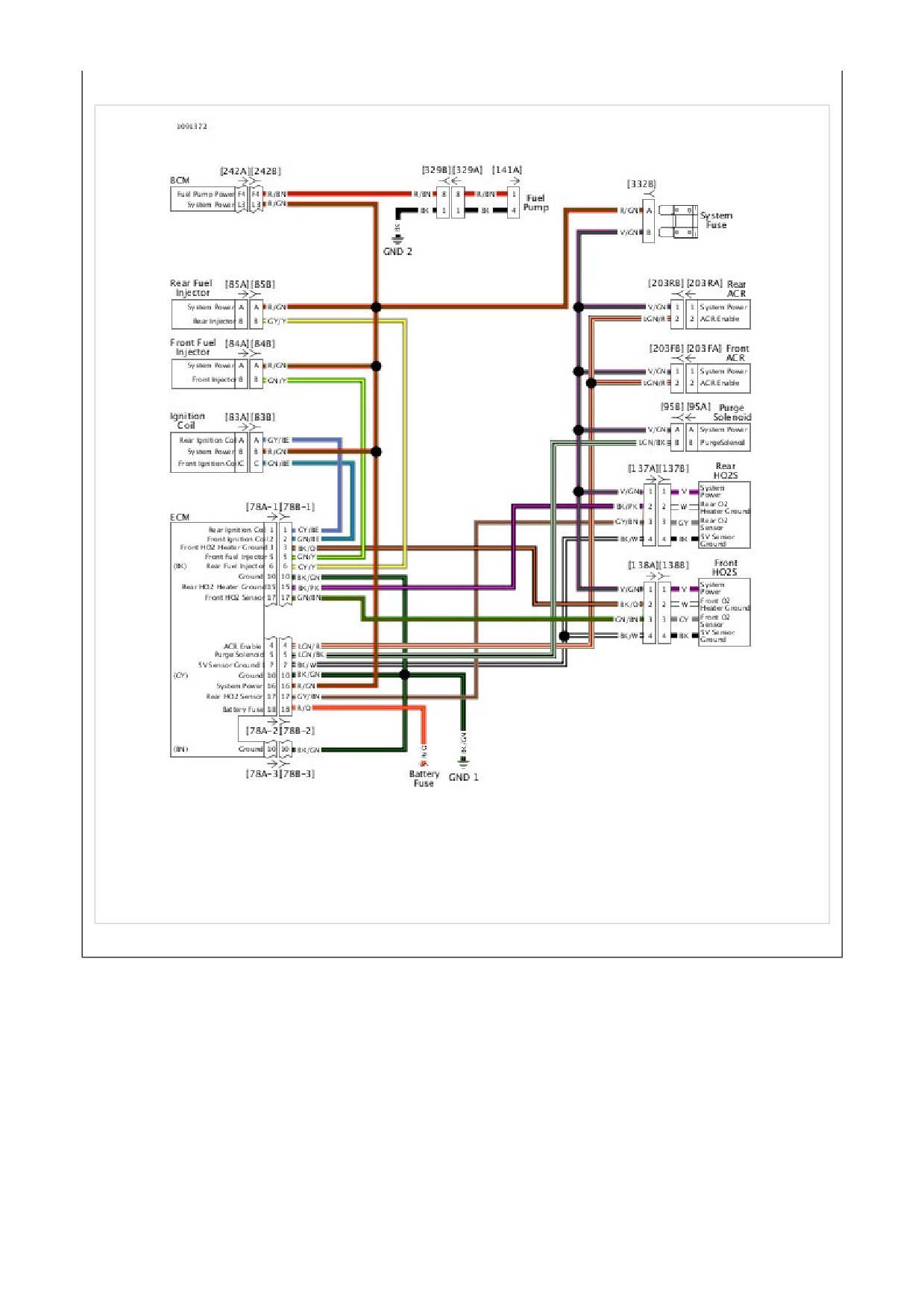
See Figure 1 , Figure 2 , Figure 3 , Figure 4 and Figure 5. The BCM supplies and monitors the 12V system power circuit
from terminal L3 of the BCM to the following components:
Ignition coil
Front fuel injector
Rear fuel injector
Purge solenoid
ECM
Front HO2S
Rear HO2S
Front ACR
Rear ACR
The system power circuit is energized when the ignition is turned on.
Table 1. Code Description
DTC
DESCRIPTION
B2102
System power output shorted high
B2103
System power output shorted low
B2104
System power output overloaded
1
CKP [79]
2
Voltage regulator [77]
3
Oil pressure sensor [120]
4
Front HO2S [138]
5
Rear brake switch [121-1]
6
Rear brake switch [121-2]
7
JSS [133]
8
Stator [47]
Figure 1. Front of Engine: Typical
1
Battery tender [281]
2
DLC [91]
3
Termination resistor [319]
4
P&A accessory [325]
5
Fuse holder [332]
6
Fuse block [64]
7
ECM [78-3]
8
ECM [78-2]
9
ECM [78-1] (behind sub caddy)
Figure 2. Behind Left Side Cover
1
Engine harness [145]
2
ABS EHCU [166]
3
Rear HO2S [137]
4
Starter solenoid [128]
5
Rear WSS [168]
Figure 3. Behind Right Side Cover
1
Front knock sensor [315]
2
Front ACR [203F]
3
Rear knock sensor [316]
4
Rear ACR [203R]
5
Rear injector [85]
6
TMAP [80]
7
Ignition coil [83]
8
Throttle control [211]
9
Front injector [84]
Figure 4. Engine
1
Purge solenoid [95]
2
GND 2A
3
GND 1
4
GND 2
5
Backbone harness interconnect [327]
6
Engine harness interconnect [328]
7
Engine harness [145]
8
Security antenna [209]
9
Left rear lighting [19]
10
Right rear lighting [18]
11
Tail lamp [40]
Figure 5. Under Seat
Conditions for Setting
DTC B2104 will set if the system power circuit draws more than 10 Amps.
Diagnostic Tips
Since the system power circuit normally has ignition voltage with IGN ON, the short to voltage will have to be present
with the vehicle turned off in order to set DTC B2102.
When disconnecting connectors, always inspect connector for corrosion or backed out terminals and repair as
required.
Connector Information
For additional information about the connectors in the following diagram(s) and diagnostic procedure(s), see General.
Figure 6. System Power Circuit

Special Tools
Description
Part Number
Qty.
TEST CONNECTOR KIT
HD-41404
1
BREAKOUT BOX
HD-50390-1
1
ECM CABLE
HD-50390-4
1
ECM OVERLAY
HD-50390-4-P
1
Table 1. DTC B2102 Diagnostic Faults
POSSIBLE CAUSES
Short to battery in the system power circuit
1. System Power Circuit Short to Voltage Test
1. Turn IGN OFF.
2. Connect BREAKOUT BOX (Part Number:HD-50390-1) and ECM CABLE (Part Number:HD-50390-4) to
[78B-1], 78B-2] and [78B-3], leaving ECM [78A-1], [78A-2] and [78A-3] disconnected. See How To Use
Diagnostic Tools.
3. Verify ECM OVERLAY (Part Number:HD-50390-4-P) is in position on BOB.
4. Using TEST CONNECTOR KIT (Part Number:HD-41404), test voltage between BOB [78-2] terminal 16 and
ground.
5. Is battery voltage present?
a. Yes. Repair short to voltage in (R/GN) wire.
b. No. Replace BCM.

Special Tools
Description
Part Number
Qty.
TEST CONNECTOR KIT
HD-41404
1
BREAKOUT BOX
HD-50390-1
1
BCM CABLE
HD-50390-2
1
BCM OVERLAY
HD-50390-2-P
1
Table 1. DTC B2103, B2104 Diagnostic Faults
POSSIBLE CAUSES
Short to ground in the system power circuit
Ignition coil resistance too low
Front coil shorted low
Rear coil shorted low
Front HO2S resistance too low
Rear HO2S resistance too low
Front fuel injector resistance too low
Rear fuel injector resistance too low
ACR resistance too low
Purge solenoid resistance too low
1. Fuse Test
1. Inspect the system fuse.
2. Is the fuse good?
a. Yes. Go to Test 2.
b. No. Go to Test 14.
2. Ignition Coil Test
1. Turn IGN OFF.
2. Disconnect ignition coil [83].
3. Clear DTCs.
4. Turn IGN ON.

5. Check DTCs.
6. Did DTC reset?
a. Yes. Go to Test 3.
b. No. Replace ignition coil.
3. Rear Coil Shorted to Ground Test
1. Using TEST CONNECTOR KIT (Part Number:HD-41404), test continuity between [83B] terminal A and
ground.
2. Is continuity present?
a. Yes. Repair short to ground on (GY/BE) wire.
b. No. Go to Test 4.
4. Front Coil Shorted to Ground Test
1. Test continuity between [83B] terminal C and ground.
2. Is continuity present?
a. Yes. Repair short to ground on (GN/BE) wire.
b. No. Go to Test 5.
5. Rear Fuel Injector Test
1. Turn IGN OFF.
2. Connect [83].
3. Disconnect rear fuel injector [85].
4. Clear DTCs.
5. Turn IGN ON.
6. Check DTCs.
7. Did DTC reset?
a. Yes. Go to Test 6.
b. No. Replace rear fuel injector.
6. Front Fuel Injector Test
1. Turn IGN OFF.
2. Connect [85].
3. Disconnect front fuel injector [84].
4. Clear DTCs.
5. Turn IGN ON.
6. Check DTCs.
7. Did DTC reset?
a. Yes. Go to Test 7.
b. No. Replace front fuel injector.
7. Purge Solenoid Test

1. Turn IGN OFF.
2. Disconnect purge solenoid [95].
3. Clear DTCs.
4. Turn IGN ON.
5. Check DTCs.
6. Did DTC reset?
a. Yes. Go to Test 8.
b. No. Replace purge solenoid.
8. Front HO2S Test
1. Turn IGN OFF.
2. Connect [95].
3. Disconnect front HO2S [138].
4. Clear DTCs.
5. Turn IGN ON.
6. Check DTCs.
7. Did DTC reset?
a. Yes. Go to Test 9.
b. No. Replace front HO2S.
9. Rear HO2S Test
1. Turn IGN OFF.
2. Connect [138].
3. Disconnect rear HO2S [137].
4. Clear DTCs.
5. Turn IGN ON.
6. Check DTCs.
7. Did DTC reset?
a. Yes. Go to Test 10.
b. No. Replace rear HO2S.
10. Front ACR Test
1. Turn IGN OFF.
2. Connect [137].
3. Disconnect front ACR [203F].
4. Clear DTCs.
5. Turn IGN ON.
6. Check DTCs.
7. Did DTC reset?
a. Yes. Go to Test 11.
b. No. Replace front ACR.
11. Rear ACR Test
1. Turn IGN OFF.
2. Connect [203F].
3. Disconnect rear ACR [203R].
4. Clear DTCs.
5. Turn IGN ON.
6. Check DTCs.
7. Did DTC reset?
a. Yes. Go to Test 12.
b. No. Replace rear ACR.
12. ECM Test
1. Turn IGN OFF.
2. Connect [85].
3. Disconnect ECM [78-2].
4. Clear DTCs.
5. Turn IGN ON.
6. Check DTCs.
7. Did DTC reset?
a. Yes. Go to Test 13.
b. No. Replace ECM.
13. BCM Test
1. Turn IGN OFF.
2. Connect [78].
3. Connect BREAKOUT BOX (Part Number:HD-50390-1) and BCM CABLE (Part Number:HD-50390-2) to wire
harness [242B] leaving BCM [242A] disconnected. See How To Use Diagnostic Tools.
4. Verify BCM OVERLAY (Part Number:HD-50390-2-P) is in position on BOB.
5. Test continuity between BOB terminal L3 and ground.
6. Is continuity present?
a. Yes. Repair short to ground in (R/GN) wire.
b. No. Replace BCM.
14. System Power Short to Ground Test
1. Test continuity between fuse block [64B] socket terminal 3 and ground.
2. Disconnect front and rear HO2S, front and rear ACRs, purge solenoid and active exhaust (if equipped).
3. Was continuity lost as components were removed?
a. Yes. Replace last component removed when continuity was lost.
b. No. Repair short to ground in (V/GN) wire.
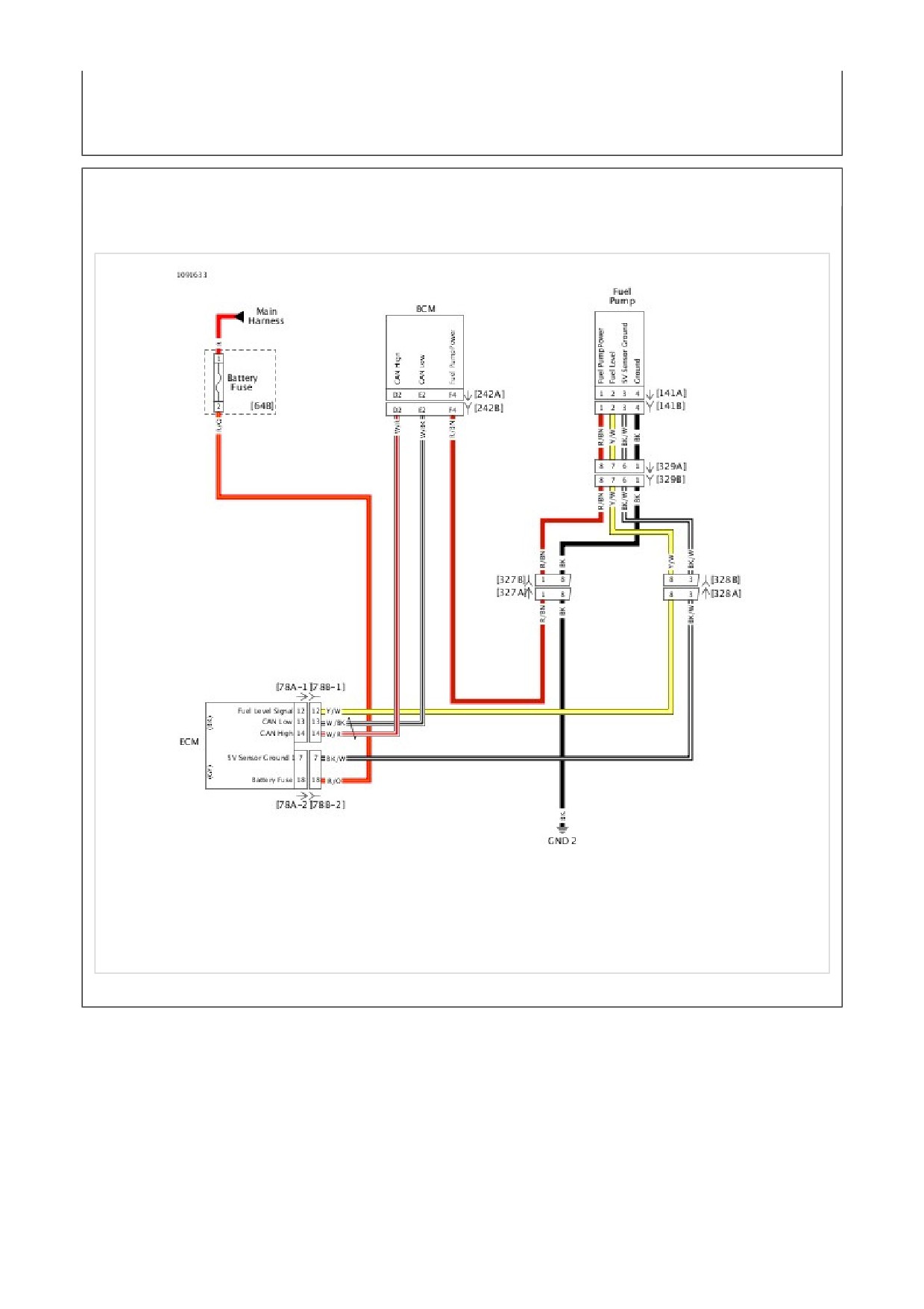
See Figure 1. The BCM supplies and monitors the 12V system power circuit from terminal F4 of the BCM to the fuel pump.
The fuel pump is constantly grounded. The BCM controls the fuel pump by turning on and off the power to the pump on
the (R/BN) wire.
1
USB caddy interconnect [329]
2
USB [264]
3
Fuel pump [141]
4
ET sensor [90]
Figure 1. Under Fuel Tank Left Side
Table 1. Code Description
DTC
DESCRIPTION
B2116
Fuel pump output open
B2117
Fuel pump output shorted high
B2118
Fuel pump output shorted low
B2119
Fuel pump output overloaded
Conditions for Setting
DTC B2116 will set if the fuel pump circuit draws less than 600 milliamps.
DTC B2119 will set if the fuel pump circuit draws more than 6 Amps.
Diagnostic Tips
DTC B2119 can set if the BCM sees an excessive load on the fuel pump circuit. This could be caused by a fuel pump
being run dry. If the fuel pump was replaced or the vehicle was run out of gas, prime the pump and clear the code.
Start the vehicle and check DTCs to see if the code returns.
Any circuit that is powered up continually with IGN ON could cause DTC B2117 or B2119 to set if shorted to the fuel
pump circuit. If a short to voltage or overload conditon is found, test continuity between fuel pump circuit and the other
power circuits from the BCM.
Connector Information
For additional information about the connectors in the following diagram(s) and diagnostic procedure(s), see General.
Figure 2. Fuel Sensor Circuit

Special Tools
Description
Part Number
Qty.
TEST CONNECTOR KIT
HD-41404
1
BREAKOUT BOX
HD-50390-1
1
BCM CABLE
HD-50390-2
1
BCM OVERLAY
HD-50390-2-P
1
Table 1. DTC B2116 Diagnostic Faults
POSSIBLE CAUSES
Open in the fuel pump power circuit
Fuel pump fault or malfunction
1. Fuel Pump Circuit Test
1. Turn IGN OFF.
2. Disconnect fuel pump [141].
3. Using TEST CONNECTOR KIT (Part Number:HD-41404), test voltage between [141B] terminals 1 and 4.
4. Turn IGN ON.
5. Was battery voltage displayed for a short time?
a. Yes. Replace fuel pump.
b. No. Go to Test 2.
2. Ground Circuit Open Test
1. Turn IGN OFF.
2. Test resistance between [141B] terminal 4 and ground.
3. Is resistance less than 0.5 ohms?
a. Yes. Go to Test 3.
b. No. Repair open in (BK) ground wire.
3. Power Circuit Open Test
1. Connect BREAKOUT BOX (Part Number:HD-50390-1) and BCM CABLE (Part Number:HD-50390-2) to wire
harness [242B], leaving BCM [242A] disconnected. See How To Use Diagnostic Tools.
2. Verify BCM OVERLAY (Part Number:HD-50390-2-P) is in position on BOB.
3. Test resistance between BOB terminal F4 and [141B] terminal 1.
4. Is resistance less than 0.5 ohm?
a. Yes. Replace BCM.
b. No. Repair open in (R/BN) wire.
Table 1. DTC B2117 Diagnostic Faults
POSSIBLE CAUSES
Short to voltage in the fuel pump power circuit
1. Fuel Pump Power Circuit Short to Voltage Test
1. Turn IGN ON.
2. Does fuel pump continue to run after the initial 2 second start up?
a. Yes. Repair short to voltage in (R/BN) wire. See diagnostic tips. If no source of short is found, replace
BCM.
b. No. Go to Test 2.
2. Code Verification Test
1. Clear DTC.
2. Start engine.
3. Check DTCs.
4. Did DTC reset?
a. Yes. Replace BCM.
b. No. Concern is intermittent. See Wiggle Test.

Table 1. DTC B2118, B2119 Diagnostic Faults
POSSIBLE CAUSES
Short to ground in the fuel pump power circuit
Fuel pump malfunction
1. Fuel Test
1. Verify there is fuel in fuel tank.
2. Is fuel present in tank?
a. Yes. Go to Test 2.
b. No. Fill tank with fuel and clear DTCs. If the DTC returned, then continue with tests. Go to Test 2.
2. Fuel Pump Test
1. Turn IGN OFF.
2. Disconnect fuel pump [141].
3. Clear DTC.
4. Turn IGN ON.
5. Check DTCs.
6. Did DTC reset?
a. Yes. Go to Test 3.
b. No. Replace fuel pump.
3. Power Circuit Short to Ground Test
1. Turn IGN OFF.
2. Disconnect BCM [242].
3. Test continuity between [141B] terminal 1 (R/BN) wire and ground.
4. Is continuity present?
a. Yes. Repair short to ground on (R/BN) wire.
b. No. See diagnostic tips. If problem not found, replace BCM.
Special Tools
Description
Part Number
Qty.
VACUUM PUMP
HD-23738
1
See Figure 1. The TMAP sensor provides the functions of both an IAT sensor and a MAP sensor in one unit. The TMAP
sensor is supplied 5V from ECM [78-3] terminal 18. It sends MAP and IAT signals back to ECM [78-1] terminal 7 and
[78-2] terminal 6, respectively. Refer to Table 1.
Table 1. Code Description
DTC
DESCRIPTION
P0107
MAP sensor open/low
P0108
MAP sensor high
P0112
IAT sensor voltage low
P0113
IAT sensor open/high
TMAP: MAP Signal
The MAP signal varies in accordance with engine vacuum and atmospheric pressure. Changes in atmospheric
pressure are influenced by weather and altitude.
TMAP: IAT Signal
The IAT portion of the TMAP sensor is a thermistor device. At a specific temperature, it will have a specific resistance
across its terminals. As this resistance varies, so does the voltage on [78-2] terminal 6 of the ECM.
At high temperatures, the resistance of the IAT sensor is very low, which effectively lowers the signal voltage on
[78-2] terminal 6.
At low temperatures, the resistance is very high, allowing the voltage to rise close to 5V. The ECM monitors this
voltage to compensate for various operating conditions.
1
Front knock sensor [315]
2
Front ACR [203F]
3
Rear knock sensor [316]
4
Rear ACR [203R]
5
Rear injector [85]
6
TMAP [80]
7
Ignition coil [83]
8
Throttle control [211]
9
Front injector [84]
Figure 1. Engine
Diagnostic Tips: MAP Portion of TMAP Sensor
DTCs P0107 or P0108 will set if the MAP sensor signal is out of range. DTC P0108 can only be detected with the
engine running.
Using the VACUUM PUMP (Part Number:HD-23738), apply a vacuum to the pressure port of the TMAP sensor.
The MAP signal voltage should lower as the vacuum is applied.
The TMAP and TGS are connected to the same reference line (+5V Vref). If the reference line goes to ground or
open, multiple codes will be set (DTCs P0107, P0108, P0122, P0123, P1501 and P1502).
Connector Information
For additional information about the connectors in the following diagram(s) and diagnostic procedure(s), see General.
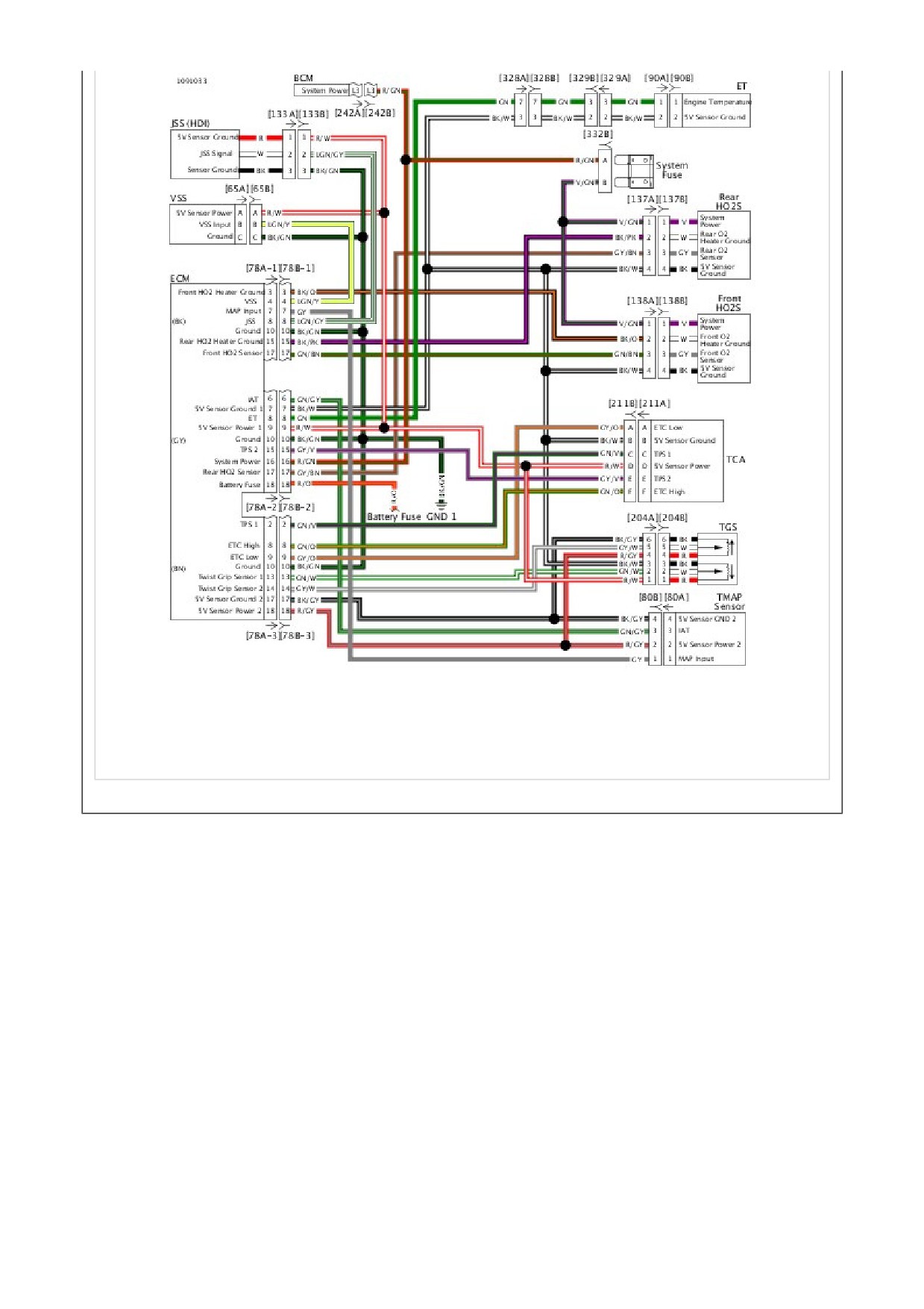
Figure 2. Sensor Circuit

Special Tools
Description
Part Number
Qty.
TEST CONNECTOR KIT
HD-41404
1
BREAKOUT BOX
HD-50390-1
1
ECM CABLE
HD-50390-4
1
ECM OVERLAY
HD-50390-4-P
1
Table 1. DTC P0107 Diagnostic Faults
POSSIBLE CAUSES
MAP sensor malfunction
Open or shorted to ground signal wire
Open or shorted to ground 5V reference circuit
1. MAP Sensor Test
1. Turn IGN OFF.
2. Disconnect TMAP sensor [80].
3. Using TEST CONNECTOR KIT (Part Number:HD-41404), jumper between [80B] terminals 1 (GY) wire and 3
(R/GY) wire.
4. Clear DTCs.
5. Start engine.
6. Turn IGN ON.
7. Check DTCs.
8. Did DTC reset?
a. Yes. Go to Test 2.
b. No. Replace TMAP sensor.
2. MAP Sensor Signal Voltage Test
1. Turn IGN OFF.
2. Remove jumper.
3. Turn IGN ON.
4. Test voltage between [80B] terminal 2 (R/GY) wire and ground.
5. Is voltage approximately 5V?
a. Yes. Go to Test 3.
b. No. Go to Test 6.
3. MAP Sensor Signal Wire Continuity Test

1. Turn IGN OFF.
2. Connect BREAKOUT BOX (Part Number:HD-50390-1) and ECM CABLE (Part Number:HD-50390-4) to
wiring harness [78B-1], [78B-2] and [78B-3], leaving ECM [78A-1], [78A-2] and [78A-3] disconnected. See
How To Use Diagnostic Tools.
3. Verify ECM OVERLAY (Part Number:HD-50390-4-P) is in position on BOB.
4. Test resistance between [80B] terminal 1 (GY) wire and BOB [78-1] terminal 7.
5. Is resistance less than 0.5 ohms?
a. Yes. Go to Test 4.
b. No. Repair open in (GY) wire.
4. MAP Sensor Signal Wire Shorted to Ground Test
1. Test continuity between BOB [78-1] terminal 7 and ground.
2. Is continuity present?
a. Yes. Repair short to ground in (GY) wire.
b. No. Go to Test 5.
5. MAP Sensor Signal Wire Shorted to Sensor Ground Test
1. Test continuity between BOB [78-1] terminal 7 and [78-3] terminal 17.
2. Is continuity present?
a. Yes. Repair short between (GY) and (BK/GY) wires.
b. No. Replace ECM.
6. MAP Sensor 5V Reference Wire Open Test
1. Turn IGN OFF.
2. Connect BREAKOUT BOX (Part Number:HD-50390-1) and ECM CABLE (Part Number:HD-50390-4) to
wiring harness [78B-1], [78B-2] and [78B-3], leaving ECM [78A-1], [78A-2] and [78A-3] disconnected. See
How To Use Diagnostic Tools.
3. Verify ECM OVERLAY (Part Number:HD-50390-4-P) is in position on BOB.
4. Test resistance between [80B] terminal 2 (R/GY) wire and BOB [78-3] terminal 18.
5. Is resistance less than 0.5 ohms?
a. Yes. Go to Test 7.
b. No. Repair open in (R/GY) wire.
7. MAP Sensor 5V Reference Shorted to Signal Ground Test
1. Test continuity between BOB [78-3] terminals 17 and 18.
2. Is continuity present?
a. Yes. Repair short between the (R/GY) and (BK/GY) wires.
b. No. See diagnostic tips before replacement. Replace ECM.

Special Tools
Description
Part Number
Qty.
TEST CONNECTOR KIT
HD-41404
1
BREAKOUT BOX
HD-50390-1
1
ECM CABLE
HD-50390-4
1
ECM OVERLAY
HD-50390-4-P
1
Table 1. DTC P0108 Diagnostic Faults
POSSIBLE CAUSES
MAP sensor malfunction
Short to voltage
1. MAP Sensor Test
1. Turn IGN OFF.
2. Disconnect TMAP sensor [80].
3. Clear DTC.
4. Start engine.
5. Turn IGN OFF.
6. Check DTCs.
7. Did DTC reset?
a. Yes. Go to Test 2.
b. No. Replace MAP sensor.
2. MAP Sensor Signal Wire Short to 5V Test
1. Turn IGN OFF.
2. Connect BREAKOUT BOX (Part Number:HD-50390-1) and ECM CABLE (Part Number:HD-50390-4) to wire
harness [78B-1], [78B-2] and [78B-3], leaving ECM [78A-1], [78A-2] and [78A-3] disconnected. See How To
Use Diagnostic Tools.
3. Verify ECM OVERLAY (Part Number:HD-50390-4-P) is in position on BOB.
4. Using TEST CONNECTOR KIT (Part Number:HD-41404), test continuity between BOB [78-1] terminal 7 and
[78-3] terminal 18.
5. Is continuity present?
a. Yes. Repair short between (R/GY) and (GY) wires.
b. No. Go to Test 3.
3. MAP Sensor Signal Wire Short to Voltage Test
1. Turn IGN ON.
2. Test voltage between BOB [78-1] terminal 7 and ground.
3. Is voltage present?
a. Yes. Repair short to voltage in (GY) wire.
b. No. Go to Test 4.
4. MAP Sensor 5V Reference Shorted to Battery Voltage Test
1. Test voltage between BOB [78-3] terminal 18 and ground.
2. Is voltage greater than 5.25V?
a. Yes. Repair short to voltage in (R/GY) wire.
b. No. Go to Test 5.
5. MAP Sensor Ground Wire Open Test
1. Test resistance between [80B] terminal 4 and BOB [78-3] terminal 17.
2. Is resistance less than 0.5 ohms?
a. Yes. Replace TMAP sensor.
b. No. Repair open in (BK/GY) wire.

Special Tools
Description
Part Number
Qty.
TEST CONNECTOR KIT
HD-41404
1
BREAKOUT BOX
HD-50390-1
1
ECM CABLE
HD-50390-4
1
ECM OVERLAY
HD-50390-4-P
1
Table 1. DTC P0112 Diagnostic Faults
POSSIBLE CAUSES
Short to ground in 5V reference circuit
NOTE
Vehicle and sensor must be at ambient room temperature before starting diagnostic test.
1. IAT Sensor Test
1. Turn IGN OFF.
2. Disconnect TMAP sensor [80].
3. Using TEST CONNECTOR KIT (Part Number:HD-41404), test resistance between [80A] terminals 4 and 3.
4. Is resistance between 500-5000 ohms?
a. Yes. Go to Test 2.
b. No. Replace TMAP sensor.
2. IAT Sensor Signal Wire Shorted to Ground Test
1. Test resistance between [80B] terminal 3 (GN/GY) and ground.
2. Is resistance reading less than 1 ohm?
a. Yes. Repair short to ground on (GN/GY) wire.
b. No. Go to Test 3.
3. IAT Sensor Signal Voltage High Test
1. Connect BREAKOUT BOX (Part Number:HD-50390-1) and ECM CABLE (Part Number:HD-50390-4) to wire
harness [78B-1], [78B-2] and [78B-3], leaving ECM [78A-1], [78A-2] and [78A-3] disconnected. See How To
Use Diagnostic Tools.
2. Verify ECM OVERLAY (Part Number:HD-50390-4-P) is in position on BOB.
3. Test continuity between BOB [78-2] terminals 6 and 10.
4. Is continuity present?
a. Yes. Go to Test 4.
b. No. Repair short to ground on (GN/GY) wire.
4. IAT Sensor Signal Wire Shorted to Sensor Ground Test
1. Test continuity between BOB [78-2] terminal 6 and [78-3] terminal 17.
2. Is continuity present?
a. Yes. Repair short between [80B] terminals 4 and 3 (GN/GY and BK/GY) wires.
b. No. Replace ECM.

Special Tools
Description
Part Number
Qty.
TEST CONNECTOR KIT
HD-41404
1
BREAKOUT BOX
HD-50390-1
1
ECM CABLE
HD-50390-4
1
ECM OVERLAY
HD-50390-4-P
1
Table 1. DTC P0113 Diagnostic Faults
POSSIBLE CAUSES
Open or short to voltage in 5V reference circuit
NOTE
Vehicle and sensor must be at ambient temperature before starting diagnostic test.
1. IAT Sensor Test
1. Turn IGN OFF.
2. Disconnect TMAP sensor [80].
3. Using TEST CONNECTOR KIT (Part Number:HD-41404), test resistance between [80A] terminals 1 (BK/GY)
wire and 2 (GN/GY) wire.
4. Is resistance between 500-5000 ohms?
a. Yes. Go to Test 2.
b. No. Replace IAT sensor.
2. IAT Signal Voltage Test
1. Turn IGN ON.
2. Using TEST CONNECTOR KIT (Part Number:HD-41404), test voltage between [80B] terminal 3 (GN/GY) and
ground.
3. Is voltage greater than 6V?
a. Yes. Repair short to voltage on (GN/GY) wire.
b. No. Go to Test 3.
3. Signal Wire Open Test
1. Turn IGN OFF.
2. Connect BREAKOUT BOX (Part Number:HD-50390-1) and ECM CABLE (Part Number:HD-50390-4) to
wiring harness [78B-1], [78B-2] and [78B-3], leaving ECM [78A-1], [78A-2] and [78A-3] disconnected. See
How To Use Diagnostic Tools.
3. Verify ECM OVERLAY (Part Number:HD-50390-4-P) is in position on BOB.
4. Test resistance between [80B] terminal 3 (GN/GY) and BOB [78-2] terminal 6.
5. Is resistance less than 0.5 ohms?
a. Yes. Go to Test 4.
b. No. Repair open circuit in (GN/GY) wire.
4. Open Ground Wire Test
1. Test resistance between BOB [78-3] terminal 17 and [80B] terminal 4 (BK/GY).
2. Is resistance less than 0.5 ohms?
a. Yes. Go to Test 5.
b. No. Repair open in (BK/GY) wire.
5. IAT Sensor Signal Wire Shorted to Sensor Power Test
1. Test continuity between BOB [78-2] terminal 6 and [78-3] terminal 18.
2. Is continuity present?
a. Yes. Repair short between (GN/GY) and (R/GY) wires.
b. No. Replace ECM.