Harley Davidson Sportster Models 2009. Service Repair Manual - page 76
 

  Главная      Harley Davidson     Harley Davidson Sportster Models 2009. Service Repair Manual


Search            copyright infringement  


Content      ..     74      75      76      77     ..


Harley Davidson Sportster Models 2009. Service Repair Manual - page 76


BK

BK

BK

GY

GY

O/W

O/W

O/W

O/W

O

R

BN/GY

BN/GY

BN/GY

BN/GY

BN/GY

LGN/V

BK

BK

GY

BK

O/W

O

O

O

BN/GY

LGN/V

LGN/V

LGN/V

LGN/V

LGN/V

LGN/V

R/BK

R/BK

R/GY

1 2

3

12

1 2

3

12

1 2

5

7

6

1 2

5

7

6

C

B A D

C

B A D

Ser

ial

Data

Batter

y

Accessor

y

Ground

Ignition

Ser

ial

Data

Batter

y

Batter

y

Ignition

Ser

ial

Data

Ground

Accessor

y

Ground

Speedometer

TSM/TSSM/HFSM

Tachometer

To ACCY Fuse

To BATT Fuse

To INSTR Fuse

To IGN Fuse

12V ACCY

Fuse

12V BATT

Fuse

12V INSTR

Fuse

12V IGN

Fuse

3

1

2

4

Ground

Serial Data

Power

Data Link
Connector

2

1

6

7

12

2

1

6

7

12

ECM

Ser

ial

Data

5

5

GND1

GND1

GND1

[78B]

[78A]

[108A]

[108B]

[20A]

[20B]

[39A]

[39B]

[30A]

[30B]

[91A]

em01304

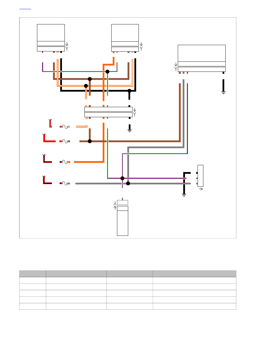
Figure 2-21. Serial Data Circuit (XR)

Table 2-14. Wire Harness Connectors

LOCATION

TYPE

DESCRIPTION

NO.

Under fuel tank

12-place Molex

Instruments

[20]

Under battery

12-place Deutsch

TSM/TSSM/HFSM

[30]

Back of speedometer

12-place Packard

Speedometer (XL)

[39]

Back of speedometer

5-place Packard

Speedometer (XR)

[39]

Under seat

36-place Packard

ECM

[78]

HOME

2-36  2009 Sportster Diagnostics:  Instruments

Table 2-14. Wire Harness Connectors

LOCATION

TYPE

DESCRIPTION

NO.

On battery strap, behind left side cover

4-place Deutsch

Data link connector

[91A]

Back of tachometer

12-place Packard

Tachometer (if equipped)

[108]

HOME

2009 Sportster Diagnostics:  Instruments  2-37

DTCs U1016 and U1255

Can you read ECM hardware Part No.?

See 2.3 ODOMETER SELF-DIAGNOSTICS.

YES

NO or “No Rsp”

While wiggling harness, check

continuity between Breakout Box

terminal 2 (Black) and terminal 5 of

ECM Breakout Box.

Is continuity present?

Check continuity between

Breakout Box terminal 2 (Black)

and terminal 5 of ECM Breakout

Box.

Is continuity present?

YES

NO

Clear codes. Test ride.

Does DTC U1016

return?

Repair intermittent

on (LGN/V) wire.

YES

Replace ECM.

Reprogram and learn

password.

No trouble found.

NO

1

2

1

2

YES

NO

Replace ECM.

Reprogram and

learn

password.

Repair open on

(LGN/V) wire.

Clear DTCs using odometer self-diagnostics. See 2.3
ODOMETER SELF-DIAGNOSTICS. Confirm proper
operation with no check engine lamp.

fc01821_en

HOME

2-38  2009 Sportster Diagnostics:  Instruments

2.11

DTC U1064, U1255

GENERAL

Loss of TSM/TSSM/HFSM Serial Data

The serial data line provides a means for the ECM,
TSM/TSSM/HFSM, speedometer, and tachometer to commu-
nicate their current status. When all operating parameters on
the serial data line are within specifications, a state of health
message is sent between the components.

DTC U1064 indicates that the TSM/TSSM/HFSM is not
receiving this state of health message.

DTC U1255 indicates that no messages were present
during power up of the current key cycle.

DTC U1064 indicates that there was communication on
the data bus since power up, but communication was lost
or interrupted during that key cycle.

Table 2-15. Code Description

DESCRIPTION

DTC

Loss of TSM/TSSM/HFSM serial data

U1064

Serial data error/missing message

U1255

DIAGNOSTICS

TOOL NAME

PART NUMBER

BREAKOUT BOX

HD-42682

INSTRUMENT HARNESS ADAPTERS

HD-46601

Diagnostic Notes

Each reference number below correlates to a circled number
on the flowchart(s).

1.

Connect BREAKOUT BOX (Part No. HD-42682) as fol-
lows:

a.

Mate black socket housing on Breakout Box with
speedometer connector [39A] on XL, or tachometer
connector [108A] on XR using INSTRUMENT HAR-
NESS ADAPTERS (Part No. HD-46601).

b.

Mate black pin housing on Breakout Box with wire
harness connector [39B] on XL, or wire harness con-
nector [108B] on XR using INSTRUMENT HARNESS
ADAPTERS (Part No. HD-46601).

c.

Mate gray socket housing on Breakout Box with
TSM/TSSM/HFSM connector [30A].

d.

Mate gray pin housing on Breakout Box with wire
harness connector [30B].

HOME

2009 Sportster Diagnostics:  Instruments  2-39

BK

BK

BK

GY

GY

GY

O/W

O/W

O/W

O/W

O

O

O

R

BN/GY

BN/GY

BN/GY

BN/GY

BN/GY

LGN/V

BK

BK

BK

O/W

O

O

BN/GY

LGN/V

LGN/V

LGN/V

LGN/V

LGN/V

LGN/V

R/BK

R/BK

R/GY

1 2

3

12

1 2

3

12

1 2

5

7

6

1 2

5

7

6

1 2

5 6 7

1 2

5 6 7

Ignition

Ser

ial

data

Batter

y

Accessor

y

Ground

Ignition

Ser

ial

Data

Batter

y

Batter

y

Ignition

Ser

ial

Data

Ground

Accessor

y

Ground

Speedometer

TSM/TSSM/HFSM

Tachometer (Optional)

To ACCY Fuse

To BATT Fuse

To INSTR Fuse

To IGN Fuse

12V ACCY

Fuse

12V BATT

Fuse

12V INSTR

Fuse

12V IGN

Fuse

3

1

2

4

Data Link
Connector

2

1

6

7

12

2

1

6

7

12

ECM

Ser

ial

Data

5

5

GND1

GND1

GND1

[78B]

[78A]

[30A]

[30B]

[20A]

[20B]

[108A]

[108B]

[39A]

[39B]

[91A]

Ground

Serial Data

Power

em01120

Figure 2-22. Serial Data Circuit (XL)

HOME

2-40  2009 Sportster Diagnostics:  Instruments

BK

BK

BK

GY

GY

O/W

O/W

O/W

O/W

O

R

BN/GY

BN/GY

BN/GY

BN/GY

BN/GY

LGN/V

BK

BK

GY

BK

O/W

O

O

O

BN/GY

LGN/V

LGN/V

LGN/V

LGN/V

LGN/V

LGN/V

R/BK

R/BK

R/GY

1 2

3

12

1 2

3

12

1 2

5

7

6

1 2

5

7

6

C

B A D

C

B A D

Ser

ial

Data

Batter

y

Accessor

y

Ground

Ignition

Ser

ial

Data

Batter

y

Batter

y

Ignition

Ser

ial

Data

Ground

Accessor

y

Ground

Speedometer

TSM/TSSM/HFSM

Tachometer

To ACCY Fuse

To BATT Fuse

To INSTR Fuse

To IGN Fuse

12V ACCY

Fuse

12V BATT

Fuse

12V INSTR

Fuse

12V IGN

Fuse

3

1

2

4

Ground

Serial Data

Power

Data Link
Connector

2

1

6

7

12

2

1

6

7

12

ECM

Ser

ial

Data

5

5

GND1

GND1

GND1

[78B]

[78A]

[108A]

[108B]

[20A]

[20B]

[39A]

[39B]

[30A]

[30B]

[91A]

em01304

Figure 2-23. Serial Data Circuit (XR)

Table 2-16. Wire Harness Connectors

LOCATION

TYPE

DESCRIPTION

NO.

Under fuel tank

12-place Molex

Instruments

[20]

Under battery

12-place Deutsch

TSM/TSSM/HFSM

[30]

Back of speedometer

12-place Packard

Speedometer (XL)

[39]

Back of speedometer

5-place Packard

Speedometer (XR)

[39]

Under seat

36-place Packard

ECM

[78]

HOME

2009 Sportster Diagnostics:  Instruments  2-41

Table 2-16. Wire Harness Connectors

LOCATION

TYPE

DESCRIPTION

NO.

On battery strap, behind left side cover

4-place Deutsch

Data link connector

[91A]

Back of tachometer

12-place Packard

Tachometer (if equipped)

[108]

HOME

2-42  2009 Sportster Diagnostics:  Instruments

DTCs U1064 and U1255

Can you read TSM/TSSM/HFSM hardware Part No.?

See 2.3 ODOMETER SELF-DIAGNOSTICS.

YES

NO

While wiggling harness, check

for continuity between

Breakout Box terminal 3

(Gray) and Breakout Box

terminal 2 (Black).

Is continuity present?

Check for continuity

between Breakout Box

terminal 3 (Gray) and

Breakout Box terminal 2

(Black).

Is continuity present?

YES

NO

Clear codes. Test ride.

Does DTC U1064

return?

Repair intermittent

on (LGN/V) wire.

YES

NO

Replace ECM.

Reprogram and learn

password.

No trouble found.

YES

NO

Replace TSM/TSSM/HFSM.

Perform password learn.

Repair open on

(LGN/V) wire.

1

1

Clear DTCs using odometer self-diagnostics. See 2.3
ODOMETER SELF-DIAGNOSTICS. Confirm proper
operation with no check engine lamp.

fc01822_en

HOME

2009 Sportster Diagnostics:  Instruments  2-43

2.12

DTC U1300, U1301 OR BUS ER

GENERAL

Serial Data Low or Serial Data Open/High

The typical serial data voltage range is 0 volts (inactive) to 7
volts (active). Due to the short pulse, voltages will be much
lower on a DVOM. In analog mode, a DVOM reading serial
data will show continuous voltage when active, typically 0.6-
0.8 volts. The range for acceptable operations is 0-7.0 volts.

Table 2-17. Code Description

DESCRIPTION

DTC

Serial data low

U1300

Serial data open/high

U1301

ed01340

Figure 2-24. Data Link Connector [91A] (Behind Left Side

Cover)

DIAGNOSTICS

Diagnostic Tips

If serial data is shorted, these Diagnostic Trouble Codes
(DTCs) will automatically cause the check engine lamp to
illuminate. The odometer will read "BUS Er" in this condi-
tion.

DTCs P1009 and P1010 may accompany DTCs U1300
and U1301.

Diagnostic Notes

If a U1300, U1301 or "BUS Er" is present, perform diagnostic
procedures listed in 

4.11 STARTS, THEN STALLS

.

HOME

2-44  2009 Sportster Diagnostics:  Instruments

TABLE OF CONTENTS

SUBJECT

............................................................................................................................

PAGE NO.

3.1 TURN SIGNAL OVERVIEW.......................................................................................................3-1
3.2 HARLEY-DAVIDSON SMART SECURITY SYSTEM.................................................................3-2
3.3 H-DSSS ACTUATION................................................................................................................3-5
3.4 PERSONAL IDENTIFICATION NUMBER (PIN)........................................................................3-6
3.5 ARMING/DISARMING SECURITY SYSTEM............................................................................3-8
3.6 WARNINGS AND ALARMS.....................................................................................................3-10
3.7 SERVICE/EMERGENCY FUNCTIONS...................................................................................3-11
3.8 TROUBLESHOOTING.............................................................................................................3-12
3.9 CHECKING FOR DIAGNOSTIC TROUBLE CODES..............................................................3-13
3.10 INITIAL DIAGNOSTIC CHECK: TSM/HFSM.........................................................................3-16
3.11 ODOMETER SELF-DIAGNOSTICS......................................................................................3-24
3.12 BREAKOUT BOX: TSM/HFSM..............................................................................................3-26
3.13 FAILS TO DISARM (HFSM ONLY)........................................................................................3-28
3.14 DTC B0563............................................................................................................................3-31
3.15 TSM/HFSM: TURN SIGNAL ERRORS AND DTCS..............................................................3-32
3.16 DTC B1131, B1132 (HFSM ONLY)........................................................................................3-48
3.17 DTC B1134............................................................................................................................3-51
3.18 DTCS B1135, B1136, B1141, AND B1142............................................................................3-54
3.19 DTC B1143, B1144, B1145 (HFSM ONLY)...........................................................................3-58
3.20 DTC B1154, B1155...............................................................................................................3-61
3.21 DTC U1016, U1255...............................................................................................................3-65
3.22 DTC U1300, U1301 OR BUS ER..........................................................................................3-70
3.23 TSM/HFSM: PASSWORD LEARN.........................................................................................3-71
3.24 HFSM MAINTENANCE.........................................................................................................3-72

TSM/HFSM

NOTES

3.1

TURN SIGNAL OVERVIEW

GENERAL

The TSM has two major functions:

Control turn signals.

Serve as BAS.

The optional, factory-installed, Harley-Davidson Smart Security
System (H-DSSS) includes a HFSM, which provides the same
functions as the TSM, but also includes security and immobil-
ization functions.

SECURITY SYSTEM: JAPAN/KOREA

The security system on motorcycles sold in Japan and Korea
meet the regulatory requirements for those countries. The
system incorporates a TSSM. Complete details on operation,
troubleshooting, and diagnostics are found in 

E.1 TSM/TSSM

(JAPAN/KOREA) OVERVIEW

.

TURN SIGNAL FUNCTIONS

Manual turn signal control: Manual activation/deactiva-
tion of left and right turn signal flashing sequences.

Automatic turn signal cancellation: Automatic cancella-
tion of left and right turn signal flashing sequences based
on either vehicle speed, vehicle acceleration or turn com-
pletion.

Hazard warning 4-way flashers: Four-way left and right
turn signal flashing capability.

Turn signal lamp diagnostics: Self-diagnostics for short
circuit and open lamp conditions on both left and right turn
signal systems. See 

3.9 CHECKING FOR DIAGNOSTIC

TROUBLE CODES

.

NOTE

The turn signals cannot be activated or deactivated when the
ignition switch is in the ACC position. The turn signals can only
be activated or deactivated with the ignition switch in the
IGNITION position.

MANUAL CANCELLATION

To stop the turn signals from flashing, briefly depress the turn
signal switch a second time.

To switch turn direction signals, depress the switch for the
opposite turn signal. The first signal is cancelled and the
opposite side begins flashing.

AUTOMATIC CANCELLATION

Press the left or right turn switch to activate automatic turn
signal cancellation. There is no need to hold the turn switch in
when approaching the turn. The TSM/HFSM will not cancel
the signal before the turn is actually completed.

When the directional switch is released, the system starts
a 20 count. As long as the vehicle is traveling above 7

MPH (11.3 km/h) the directional will always cancel after
20 flashes if the system does not recognize any other
input.

If the vehicle speed drops to 7 MPH (11.3 km/h) or less,
including stopped, the directionals will continue to flash.
Counting will resume when vehicle speed reaches 8 MPH
(12.9 km/h) and will automatically cancel when the count
total equals 20 as stated above.

The turn signals will cancel within two seconds upon turn
completion. A sensor inside the TSM/HFSM cancels the
signal after the vehicle has been returned to an upright
position.

NOTE

The bank angle cancellation function has an automatic calibra-
tion feature. Ride the motorcycle for 0.25 miles (0.4 km) at
steady speeds (upright) to calibrate the system. Performance
of bank angle function may not be optimal until this calibration
is performed. This self-calibration is performed automatically
every time the vehicle is started and ridden.

BANK ANGLE FUNCTIONS

Emergency engine shutdown: Will provide engine
shutdown when vehicle is tipped over.

Emergency outputs disable: Will disable turn signal
lamps and starter motor when vehicle is tipped over.

BANK ANGLE RESTART

The engine will shut off automatically if the vehicle is tipped
over. The turn signals, starter motor, ECM, fuel pump and coil
will be disabled.

The odometer displays "tIP" when a tip over condition is
detected.

To restart the motorcycle after shutdown has occurred:

1.

Return the motorcycle to an upright position.

2.

Cycle the ignition switch OFF-ON before restarting the
motorcycle.

CLUTCH/NEUTRAL INTERLOCK

Disables starter: Disables starter until either the clutch
lever is pulled in or transmission neutral is selected.

Diagnostics: Provides diagnostics for clutch and neutral
switch faults.

SECURITY SYSTEM H-DSSS

See 

3.2 HARLEY-DAVIDSON SMART SECURITY SYSTEM

.

HOME

2009 Sportster Diagnostics: TSM/HFSM  3-1

3.2

HARLEY-DAVIDSON SMART SECURITY SYSTEM

COMPONENTS

The H-DSSS consists of three components:

Hands-Free Security Module: See 

Figure 3-1

. A elec-

tronic module that functions both as the TSM and as the
HFSM.

Hands-Free Antenna: See 

Figure 3-1

. Mounted under

the seat of the motorcycle.

Hands-Free Fob: See 

Figure 3-2

. A remote control device,

intended to be carried by the rider whenever the vehicle
is being operated.

NOTE

Do not relocate any of the Security System components.

ed02826

Figure 3-1. HFSM and Antenna

ed02044

Figure 3-2. Hands-Free Fob w/Serial Number Label

SECURITY IMMOBILIZATION

The HFSM provides security and immobilization functions not
found on the TSM. The HFSM will disable the starter and igni-
tion system. Additional functions include the ability to alternately
flash the left and right turn signals and sound a siren (if
equipped) if a theft attempt is detected.

NOTE

The siren must be in the Chirp Mode for the siren to chirp on
arming or disarming. See 

3.6 WARNINGS AND ALARMS,

Siren Chirp Mode (Confirmation)

.

Conditions that activate the security system when system is
armed include:

Detecting tampering of the ignition circuit: Turn signals
flash three times, optional siren chirps once and then turns
off. If the tampering continues, a second warning will
activate after four seconds. Continued tampering will cause
the alarm to activate for 30 seconds and then turn off. The
two warnings/alarm cycle is repeated for each tampering
incident.

Detecting vehicle movement: Turn signals flash three
times, optional siren chirps once and then turns off. If the
vehicle is not returned to its original position, a second
warning will activate after four seconds. If the vehicle is
not returned to its original position, the alarm activates for
30 seconds then turns off. The two warnings/alarm cycle
may repeat a maximum of 10 times with a 10 second
pause between cycles.

Detecting that a battery or ground disconnect has
occurred while armed:
 Siren, if installed, activates its
self-alarm mode. Turn signals will not flash.

HOME

3-2  2009 Sportster Diagnostics: TSM/HFSM

See 

3.5 ARMING/DISARMING SECURITY SYSTEM

 for more

information.

NOTE

Disconnect the battery to prevent the siren (if installed) from
activating within 5 seconds of turning the ignition switch to
OFF/FORK LOCK. If the HFSM is armed, you must turn the
ignition switch to IGNITION with a fob within range, again turn
the ignition switch to OFF/FORK LOCK and remove the
MAXIFUSE before the 5-second arming period expires. With
the MAXIFUSE removed, the battery can be disconnected.

HFSM FEATURES

TOOL NAME

PART NUMBER

DIGITAL TECHNICIAN II

HD-48650

The following information applies only to motorcycles equipped
with the Hands-Free Security System (HFSM).

Security lamp: See 

Figure 3-3

. A lamp (key icon) within

the speedometer face on XL, or tachometer face on XR,
tells the rider if the system is armed or disarmed.

Personal code disarming: If the fob is not available, the
HFSM allows the rider to disable the security alarm and
immobilization functions with a five-digit personal code.

Arming confirmation: When the HFSM is armed, the
system provides visual feedback (confirmation) to the rider
by flashing the turn signals and an audible "chirp" if
equipped with the optional smart siren and chirp mode is
enabled.

Disarming confirmation: When the HFSM is disarmed,
the system provides an audible "chirp" (confirmation) if
equipped with the optional smart siren and chirp mode is
enabled.

Transport mode: It is possible to arm the security system
without enabling the motion detector for one ignition cycle.
This allows the vehicle to be moved in an immobilized
state.

Starter/ignition disable: When armed the starter and
ignition system are disabled.

Security system alarm: See 

Figure 3-4

The system will

alternately flash the left and right turn signals and sound
an optional Security Siren if a vehicle security condition
is detected while the system is armed.

Dealer service mode: This mode allows the dealer to
disable security system via DIGITAL TECHNICIAN II (Part

No. HD-48650). Dealer service mode is exited when
module detects an assigned fob in range.

ed02920

Figure 3-3. Security Lamp (Key Icon) (Typical)

ed02047

Figure 3-4. Security Siren

HOME

2009 Sportster Diagnostics: TSM/HFSM  3-3

1

3

3

Battery

Serial

Data

Serial

Data

Battery

Fuse

15A

IGN Fuse

15A

ACC Fuse

15A

4

2

1

2

1

Receive Antenna

Transmit Antenna A

Transmit Antenna B

3

2

1

2

1

2

5

2

2

5

12

4

7

8

2

1

3

12

4

7

8

2

1

3

B

B

6

5

9

10

11

6

5

9

10

11

30 Amp
MAXIFUSE

Fuse

Block

Ignition

Switch

Data Link

Connector

ECM

Speedometer-XL

Tachometer-XR

Right Turn

Switch

Clutch

Switch

Security
Siren
(Optional)

Left Turn

Switch

Neutral

Switch

Receive

Hands

Free

Antenna

HFSM

TSM/HFSM

Right Turn

Lamps

Left Turn

Lamps

BK

BK

BK

BN

BN

BN

BN

BK

BK

BK

BK

BK

BK

BK

BK

BK

GY

TN

TN

BK

BK

R

R

V

V

V

V

R

R

R

R/BK

R/GY

BK/R

BK/R

BN/GY

GY

BN/GY

LGN/V

LGN/V

LGN/BN

LGN/BN

LGN/V

LGN/V

LGN/V

Y/BK

Y/BK

O/Y

O/Y

O/W

O/W

W/BN

W/V

O/W

[78B]

[78A]

[91A]

[39A] [39B]-XL

[108A] [108B]-XR

[209B]

[209A]

[208B]

[208A]

[142B] [142A]

[30B] [30A]

[30A] [30B]

Alarm

Signal

Battery

Clutch

Switch

Ignition

Start Relay

Control

Left Turn
Switch Input

Right Turn
Switch Input

Serial Data

Left Turn

Feed

Neutral
Switch

Right Turn

Feed

Ground

30

87

86

85

Start
Relay

Starter

Engine

Stop Switch

Start

Switch

To

Battery

Positive

To

Ignition

Switch

To

Ignition

Fuse

To

ECM

GN

BK

GY

BK

R/BK

W/BK

W/BK

W/BK

BK/R

TN/GN

em01317

Figure 3-5. Simplified TSM/HFSM Wiring

HOME

3-4  2009 Sportster Diagnostics: TSM/HFSM

3.3

H-DSSS ACTUATION

GENERAL

Setting up a vehicle TSM/HFSM depends on whether the
vehicle has a TSM or the optional HFSM security system
installed.

SIDECAR CONFIGURATION

Only Touring Harley-Davidson Motorcycles are suitable
for sidecar use. Consult a Harley-Davidson dealer. Use of
motorcycles other than Touring models with sidecars
could result in death or serious injury. (00040a)

All motorcycles ship with the H-DSSS set for use without a
sidecar installed. If a motorcycle is equipped with a TSM, no
further actuation is required.

ACTUATION

Actuation consists of assigning two fobs to the system, and
entering an initial PIN. The PIN can be changed by the rider
at any time.

1.

Configure HFSM motorcycles by assigning both fobs to
the vehicle.

2.

Configure HFSM motorcycles by entering a PIN picked
by the owner. The personal code allows the owner to
operate the system if the fob is lost or inoperable. Record
the PIN in the Owner's Manual and instruct the customer
to carry a copy (use the wallet card found in the Owner's
Manual). See 

3.4 PERSONAL IDENTIFICATION NUMBER

(PIN)

.

Once the system has been activated, it will always "arm" within
5 seconds of turning the ignition switch to OFF and no motor-
cycle motion.

FOB ASSIGNMENT

TOOL NAME

PART NUMBER

DIGITAL TECHNICIAN II

HD-48650

Use DIGITAL TECHNICIAN II (Part No. HD-48650) to assign
both fobs to the H-DSSS. Follow the menu prompts in the
DIGITAL TECHNICIAN II (Part No. HD-48650) display and
scan the fob serial number with the bar code reader, or key-in
the number from the keyboard. See a Harley-Davidson dealer.

NOTE

Each fob has a unique serial number. The label should be
removed from the fob and attached to a blank NOTES page
in the Owner's Manual for reference.

POWER DISRUPTION AND CONFIGURING

TOOL NAME

PART NUMBER

BREAKOUT BOX

HD-42682

The HFSM will not enter PIN entry mode on the first attempt
after battery voltage has been removed from terminal 1. This
will occur after any of the following:

Battery disconnect or power drain.

Battery fuse removal.

Connecting BREAKOUT BOX (Part No. HD-42682) to
HFSM connector.

Therefore, after all battery reconnects, the configuration
sequence must be modified as follows:

1.

Set Engine Stop Switch to OFF, cycle ignition switch
IGNITION-OFF-IGNITION-OFF-IGNITION and press left
turn signal switch twice.

2.

Repeat steps listed above.

3.

Continue with PIN entry sequence listed.

HOME

2009 Sportster Diagnostics: TSM/HFSM  3-5


Content      ..     74      75      76      77     ..