Harley Davidson Sportster Models 2009. Service Repair Manual - page 36
 

  Главная      Harley Davidson     Harley Davidson Sportster Models 2009. Service Repair Manual


Search            copyright infringement  


Content      ..     34      35      36      37     ..


Harley Davidson Sportster Models 2009. Service Repair Manual - page 36


9

14

12

8

1

7

6

5

4

3

2

10

15

11

13

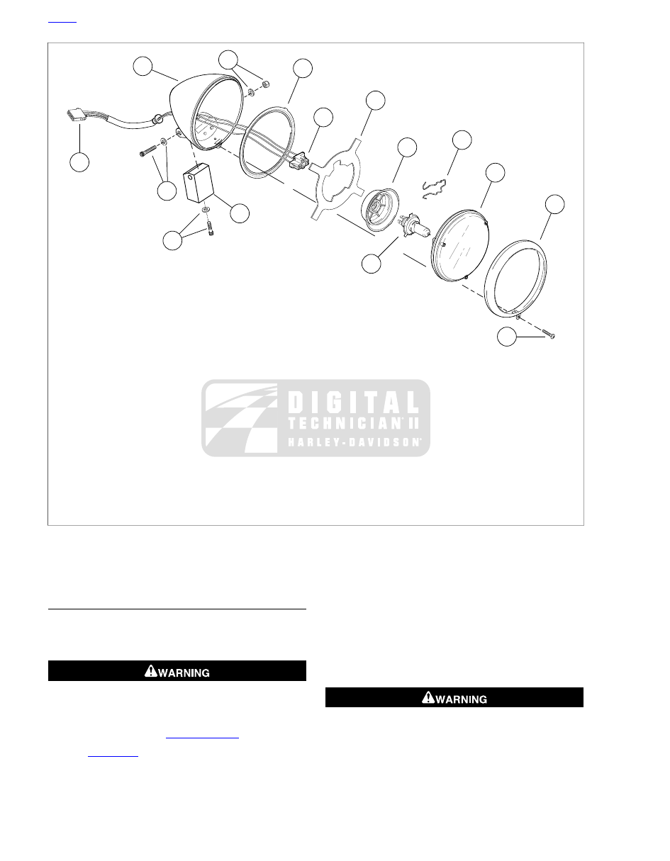
sm01667

1.

Headlamp shell

2.

Adapter ring

3.

Connector [38]

4.

Rubber finger gasket

5.

Rubber boot

6.

Retaining clip

7.

Reflector/lens

8.

Moulding ring

9.

Moulding ring screw

10. Bulb
11. Bolt and washer
12. Headlamp mount
13. Bolt and washer
14. Headlamp socket connector [38B]
15. Washer and nut

Figure 6-56. Headlamp Components: XL 883C/XL 1200C

REPLACEMENT: ALL MODELS EXCEPT XL
883C/XL 1200C

NOTE

The headlamp is a replaceable bulb (element) type. Replace
with the specified H4 halogen bulb, only.

To prevent accidental vehicle start-up, which could cause
death or serious injury, remove main fuse before pro-
ceeding. (00251b)

1.

Unplug main fuse. See 

6.38 MAIN FUSE

.

2.

See 

Figure 6-57

. Remove screw (8) and chrome outer

molding ring (6).

3.

Hold headlamp reflector/lens (5) and compress release
tabs on sides of bulb connector (10) to pull connector from
spade terminals.

4.

Pull rubber boot (3) from back of reflector/lens.

5.

Press ends of retaining clip (4) to unhook from notched
retaining tabs and pivot retaining clip back.

6.

Remove bulb (9).

To prevent accidental vehicle start-up, which could cause
death or serious injury, remove main fuse before pro-
ceeding. (00251b)

7.

Fit replacement bulb (9).

HOME

6-50  2009 Sportster Service: Electrical

10

9

16

2

3

11

7

12

1

6

8

14

4

5

13

15

sm01353

1.

Headlamp shell

2.

Adapter ring

3.

Rubber boot

4.

Retaining clip

5.

Reflector/lens

6.

Moulding ring

7.

Moulding ring nut

8.

Moulding ring screw

9.

Bulb

10. Bulb connector
11. Headlamp connector [38]
12. Headlamp bracket (XL model shown)
13. Headlamp mounting washer
14. Lockwasher
15. Nut
16. Headlamp bracket plug

Figure 6-57. Headlamp Components: All Except XL 883C/XL

1200C

NOTE

The tab opposite the center spade connector of bulb fits the
top notch in the reflector which points to the top of the
reflector/lens.

8.

Pivot the retaining clip (4) over the bulb (9) and press the
ends into the retaining post.

9.

Install rubber boot (3) with word TOP over top notch. Press
center ring down flush with base of bulb.

10. See 

Figure 6-58

. If replacing the small position lamp (3)

in the side of the reflector/lens on HDI models:

a.

Pull the spade connectors from the bulb holder.

b.

Pull the bulb holder from the reflector/lens.

c.

Quarter turn the bulb to remove and replace.

d.

Replace the bulb holder and mate connectors.

11. Mate the bulb connector to the bulb.

12. Fit the adapter ring and the reflector/lens to the headlamp

shell.

13. Install the moulding ring screw and nut.

14. Plug in main fuse. See 

6.38 MAIN FUSE

.

15. After final assembly, align headlamp as described in

1.31 HEADLAMP ALIGNMENT

.

2

1

3

sm01293

1.

Headlamp connector [38]

2.

Rubber boot

3.

HDI position lamp

Figure 6-58. HDI Headlamp (XL 1200R Shown)

HOME

2009 Sportster Service: Electrical  6-51

6.22

INDICATOR LAMP MODULE

GENERAL

The indicator lamps are LEDs housed in a self-contained, non-
repairable module. If one indicator lamp fails, the entire module
and instrument harness must be replaced.

PRELIMINARY DISASSEMBLY: ALL
MODELS

To prevent spray of fuel, purge system of high-pressure
fuel before supply line is disconnected. Gasoline is
extremely flammable and highly explosive, which could
result in death or serious injury. (00275a)

1.

Position vehicle upright. Purge the fuel supply hose of high
pressure gasoline. Disconnect fuel supply hose from fuel
pump module. See 

4.6 FUEL TANK: XL MODELS

 or

4.7 FUEL TANK: XR MODELS

.

To prevent accidental vehicle start-up, which could cause
death or serious injury, remove main fuse before pro-
ceeding. (00251b)

2.

Unplug main fuse. See 

6.38 MAIN FUSE

.

3.

Remove seat.

4.

Remove fuel tank. See 

4.6 FUEL TANK: XL MODELS

 or

4.7 FUEL TANK: XR MODELS

.

5.

See 

6.33 ELECTRICAL CADDIES

:

a.

XL models only: remove screw securing left wire
harness caddy to right wire harness caddy.

b.

Locate instruments connector [20] on right wire har-
ness caddy for XL models and on left side of caddy
for XR models. Unplug connector [20A].

6.

Make a note of the location of all cable straps securing
instrument harness to vehicle. Cut cable straps to free
instrument harness.

REPLACEMENT: XL 1200L AND XL 1200N

1.

Cover headlamp bracket with a clean soft cloth to protect
surface.

2.

See 

Figure 6-59

. Holding speedometer housing/handlebar

clamp (3), remove four screws securing housing/clamp
assembly to handlebar risers.

3.

Remove two screws (6) to separate indicator lamp module
(4) from speedometer housing/handlebar clamp, trim plate
(1) and lens (2).

1

2

3

4

5

6

sm02478

1.

Trim plate

2.

Lens

3.

Speedometer housing/handlebar clamp

4.

Indicator lamp module

5.

Instrument harness connector [20A]

6.

Screw (2)

Figure 6-59. Indicator Lamps: XL 1200L/XL 1200N

4.

See 

6.6 SPEEDOMETER: XL SINGLE GAUGE MODELS

EXCEPT XL 883C/XL 1200C

:

a.

Remove back plate from speedometer. Unplug har-
ness connector [39B] from back of speedometer.

b.

Remove trip odometer reset button boot and remove
trip odometer reset button from back plate.

5.

Remove instrument harness from vehicle.

6.

Place new instrument harness in position.

7.

See 

6.6 SPEEDOMETER: XL SINGLE GAUGE MODELS

EXCEPT XL 883C/XL 1200C

:

a.

Plug harness connector [39B] into back of speedo-
meter.

b.

Install trip odometer reset button into speedometer
back plate and thread on button boot finger-tight.

c.

Install back plate onto speedometer and secure with
two screws.

8.

See 

Figure 6-59

. Assemble trim plate (1), lens (2) and

indicator lamp module (4) onto speedometer
housing/handlebar clamp (3). Secure with two screws (6).

9.

Install housing/clamp assembly onto handlebar risers and
secure with four screws:

a.

Tighten front screws first, to 12-18 ft-lbs (16.3-24.4
Nm).

b.

Tighten rear screws to 12-18 ft-lbs (16.3-24.4 Nm).

10. Proceed to 

6.22 INDICATOR LAMP MODULE, Reas-

sembling Vehicle: All Models

.

HOME

6-52  2009 Sportster Service: Electrical

REPLACEMENT: XL 883C AND XL 1200C

1.

See 

Figure 6-60

. Remove two screws (1) and riser cover

(2) from behind handlebar riser (3).

2.

Remove four screws (4) securing speedometer
housing/handlebar clamp (5) to handlebar riser.

3.

Carefully bend back four latches (8) on indicator lamp
bezel (6) and remove indicator lamp module (7).

4.

See 

6.8 SPEEDOMETER: XL 883C/XL 1200C

.

a.

Remove two screws securing speedometer to
speedometer housing/handlebar clamp. Carefully pull
speedometer out of housing.

b.

Unplug harness connector [39B] from rear of
speedometer.

c.

Remove trip odometer reset button boot and remove
trip odometer reset button from back of speedometer
housing/handlebar clamp.

9

8

1

6

5

4

3

7

2

sm01361

1.

Screw (2)

2.

Riser cover

3.

Handlebar riser

4.

Screw (4)

5.

Speedometer housing/handlebar clamp

6.

Indicator lamp bezel with lens

7.

Indicator lamp module

8.

Latch (4)

9.

Instrument harness connector [20A]

Figure 6-60. Indicator Lamps: XL 883C/XL 1200C

5.

Carefully pull harness with connector [39B] and trip odo-
meter reset button from back of speedometer
housing/handlebar clamp.

6.

Pull instrument harness with connector [20A] up through
upper fork bracket and remove harness from vehicle.

7.

Place new instrument harness in position.

8.

Carefully feed connector [20A] end down through upper
fork bracket and along left side of frame steering head.

NOTE

Make certain that speedometer harness and trip odometer
switch harness are positioned underneath the handlebar, and
indicator lamp module harness feeds over the top of the
handlebar.

9.

Carefully feed end of harness with connector [39B] and
trip odometer reset button through back of speedometer
housing/handlebar clamp.

10. See 

6.8 SPEEDOMETER: XL 883C/XL 1200C

:

a.

Install trip odometer reset button into speedometer
housing/handlebar clamp and secure with button boot.

b.

Plug harness connector [39B] into back of speedo-
meter.

c.

Carefully slide speedometer into speedometer
housing/handlebar clamp. Secure with two screws.

11. See 

Figure 6-60

. Install indicator lamp module (7) into

back of speedometer housing/handlebar clamp (5). Secure
with four latches (8) on indicator lamp bezel (6).

12. Install speedometer housing/handlebar clamp onto

handlebar riser (3) and secure with four screws (4):

a.

Adjust handlebars to desired position.

b.

Tighten front screws first, to 12-18 ft-lbs (16.3 -24.4
Nm).

c.

Tighten rear screws to 12-18 ft-lbs (16.3 -24.4 Nm).

13. Install riser cover (2) behind handlebar riser and secure

with two screws (1). Make certain that handlebar control
harnesses are not pinched between handlebar riser and
riser cover. Tighten screws to 8-12 in-lbs (0.9-1.4 Nm).

14. Proceed to 

6.22 INDICATOR LAMP MODULE, Reas-

sembling Vehicle: All Models

REPLACEMENT: ALL OTHER MODELS

1.

Cover headlamp bracket with a clean soft cloth to protect
surface.

2.

See 

Figure 6-61

. Holding instrument bracket (3), remove

two screws with lock washers securing instrument bracket
to handlebar risers.

3.

Remove two screws (6) to separate indicator lamp module
(4) from instrument bracket, trim plate (1) and lens (2).

HOME

2009 Sportster Service: Electrical  6-53

5

2

6

1

4

3

5

1

3

4

6

2

sm01357

1.

Trim plate

2.

Lens

3.

Instrument bracket

4.

Indicator lamp module

5.

Instrument harness connector [20A]

6.

Screw (2)

Figure 6-61. Indicator Lamps: All Single and Dual Gauge

Models Except XL 883C/XL 1200C/XL 1200L/XL 1200N

4.

See 

6.6 SPEEDOMETER: XL SINGLE GAUGE MODELS

EXCEPT XL 883C/XL 1200C

6.7 SPEEDOMETER AND

TACHOMETER: XL DUAL GAUGE MODELS

, or

6.9 SPEEDOMETER AND TACHOMETER: XR MODELS

:

a.

Remove back plate from speedometer. Unplug har-
ness connector [39B] from back of speedometer.

b.

Remove trip odometer reset button boot and remove
trip odometer reset button from back plate.

c.

Dual-gauge models: remove back plate from tacho-
meter. Unplug harness connector [108B] from back
of tachometer.

5.

Remove instrument harness from vehicle.

6.

Place new instrument harness in position.

7.

See 

6.6 SPEEDOMETER: XL SINGLE GAUGE MODELS

EXCEPT XL 883C/XL 1200C

6.7 SPEEDOMETER AND

TACHOMETER: XL DUAL GAUGE MODELS

, or

6.9 SPEEDOMETER AND TACHOMETER: XR MODELS

:

a.

Plug harness connector [39B] into back of speedo-
meter.

b.

Install trip odometer reset button into speedometer
back plate and thread on button boot finger-tight.

c.

Install back plate onto speedometer and secure with
two screws.

d.

Dual-gauge models: plug harness connector [108B]
into back of tachometer. Install back plate onto
tachometer and secure with two screws.

8.

See 

Figure 6-61

. Assemble trim plate (1), lens (2) and

indicator lamp module (4) onto instrument bracket (3).
Secure with two screws (6).

9.

Install instrument bracket onto handlebar risers. Tighten
screws to 12-18 in-lbs (16.3-24.4 Nm).

10. Proceed to 

6.22 INDICATOR LAMP MODULE, Reas-

sembling Vehicle: All Models

.

REASSEMBLING VEHICLE: ALL MODELS

1.

XL models only: see 

6.33 ELECTRICAL CADDIES

:

a.

Feed instrument harness between coil bracket
uprights, back to right wire harness caddy.

b.

Plug instrument harness pin connector [20A] into
socket connector [20B] in right wire harness caddy.

c.

Mate right and left wire harness caddies. Secure with
screw and tighten.

2.

XR models only: see 

6.33 ELECTRICAL CADDIES

:

a.

Feed instrument harness along left side of frame next
to left and right hand control harnesses and inside of
coil bracket upright.

b.

Plug instrument harness pin connector [20A] into
socket connector [20B] in right wire harness caddy.

3.

Secure instrument harness to vehicle with cable straps in
locations previously noted.

4.

Install fuel tank. See 

4.6 FUEL TANK: XL MODELS

 or

4.7 FUEL TANK: XR MODELS

.

5.

Plug in main fuse. See 

6.38 MAIN FUSE

.

After installing seat, pull upward on seat to be sure it is
locked in position. While riding, a loose seat can shift
causing loss of control, which could result in death or
serious injury. (00070b)

6.

Install seat.

HOME

6-54  2009 Sportster Service: Electrical

6.23

TAIL LAMP: ALL MODELS EXCEPT XL 1200N

GENERAL

This section describes the replacement of the tail lamp bulb
as well as replacement of the entire tail lamp housing assembly
on all models except the XL 1200N. For XL 1200N, see

6.24 TURN SIGNALS

.

BULB REPLACEMENT

NOTE

Sportsters are equipped with a tail lamp incorporating a rear
lighting harness and circuit board to simplify replacement.

1.

Make certain ignition switch is turned OFF.

2.

See 

Figure 6-62

. Remove two screws and lens (4) from

base (3).

3.

Depress locking tab and remove 4-Pin multilock connector
from circuit board.

4.

Turn socket assembly (1) one-quarter turn counterclock-
wise to release assembly from lens. Remove (pull)
assembly from lens. Remove bulb from socket.

5.

Coat base of new bulb with electrical contact grease (Part
No. 99861-90). Install (push) new bulb into socket.

6.

Install (push) bulb assembly into lens. Turn assembly one-
quarter turn clockwise to lock in place.

7.

Connect 4-Pin multilock connector to circuit board.

8.

Install lens to base with two screws. Tighten screws to
20-24 in-lbs (2.3-2.7 Nm)

9.

Turn ignition on and test for proper tail lamp operation.

68140-98

4

2

1

3

sm01362

1.

Bulb/socket assembly

2.

4-pin multilock connector

3.

Base

4.

Lens

Figure 6-62. Tail Lamp (Typical, XL Models Shown)

BASE REPLACEMENT

TOOL NAME

PART NUMBER

PIN TERMINAL REMOVER

HD-39621-28

Use of the PIN TERMINAL REMOVER (Part No. HD-39621-
28) is recommended for this procedure. See 

A.1 AMP MULTI-

LOCK CONNECTORS

.

To prevent accidental vehicle start-up, which could cause
death or serious injury, remove main fuse before pro-
ceeding. (00251b)

1.

Unplug main fuse. See 

6.38 MAIN FUSE

.

2.

See 

Figure 6-62

. Remove two screws and lens (4) from

base (3).

3.

Depress locking tab and remove 4-Pin multilock connector
from circuit board.

4.

See 

Figure 6-63

. Using a terminal pick, depress locking

tabs and remove two 2-Pin turn signal connectors and 6-
Pin Power In connector from circuit board.

5.

XL models only: remove base as follows:

a.

Remove screw, pin housing and circuit board from
base.

b.

Remove base from rear fender.

6.

XR models only: see 

Figure 6-66

. Remove base as fol-

lows:

a.

Remove pin housing and circuit board from base.

b.

Remove screws (1, 2) and remove base from frame.

c.

If replacing base, remove turn signals from base. See

6.24 TURN SIGNALS

.

7.

XL models only: install base as follows:

a.

Install base on rear fender.

b.

Install screw, pin housing and circuit board to base.
Tighten screw to 45-48 in-lbs (5.1-5.4 Nm).

8.

XR models only: see 

Figure 6-66

. Install base as follows:

a.

Install base to frame with screws (1, 2). Tighten screw
to 36-60 in-lbs (4.1-6.8 Nm).

b.

Set pin housing and circuit board onto base.

9.

See 

Figure 6-65

. Install connectors to circuit board.

10. Install lens to base with two screws. Tighten screws to

20-24 in-lbs (2.3-2.7 Nm)

11. Plug in main fuse. See 

6.38 MAIN FUSE

.

12. Turn ignition on and test for proper tail lamp and turn signal

operation.

NOTE

Cavity numbers are on the back side of secondary locks on
connector housings.

HOME

2009 Sportster Service: Electrical  6-55

2

1

sm01363

1.

Terminal pick

2.

2-pin connector

Figure 6-63. Removing 2-Pin Connectors (Typical, XL

Models Shown)

H-D

USA

68830-98

1

2

sm01364

1.

Pin housing

2.

Circuit board

Figure 6-64. Pin Housing and Circuit Board

1

4

3

2

sm01365

1.

Tail lamp [93]

2.

Left turn signal [18]

3.

Right turn signal [19]

4.

Power in [94]

Figure 6-65. Tail Lamp Base Connectors (Typical, XL

Models Shown)

1

2

3

1

sm05566

1.

Screw (2)

2.

Screw

3.

Base

Figure 6-66. Tail Lamp Base: XR 1200 Only

Table 6-11. Connector Specifications

CAVITY

WIRE COLOR

NUMBER

TYPE

FUNCTION

1

V

19

2-pin Mulitlock

Right turn signal

2

BK

1

V

18

2-pin Multilock

Left turn signal

2

BK

1

BE

93

4-pin Mulitlock

Tail lamp

2

O/W*

3

R/Y

4

BK

HOME

6-56  2009 Sportster Service: Electrical

Table 6-11. Connector Specifications

CAVITY

WIRE COLOR

NUMBER

TYPE

FUNCTION

1

O/W

94

6-pin Multilock

Power

2

BN

3

BE

4

R/Y

5

V

6

BK

* HDI only. OPEN on DOM.

HOME

2009 Sportster Service: Electrical  6-57

6.24

TURN SIGNALS

GENERAL

This section describes the replacement of turn signal bulbs,
as well as the replacement of the entire turn signal housing
assembly.

The rear turn signals on the XL 1200N model also serve as
tail lamps and brake lamps. The rear turn signal/brake lamp
functions are provided by an electronic converter module. See

6.26 REAR LIGHTING CONVERTER MODULE: XL 1200N
(DOMESTIC ONLY)

 for replacement of this module.

BULB REPLACEMENT

NOTES

The HDI XL 1200N is equipped with LED rear turn
signal/brake lamp/tail lamp assemblies. These are sealed
units and cannot be disassembled. The entire rear turn
signal housing assembly must be replaced. See

6.24 TURN SIGNALS, Rear Housing Replacement

.

The Domestic XL 1200N is equipped with dual filament
rear turn signal bulbs to provide rear turn signal, brake
lamp and tail lamp functions.

All other models are equipped with single filament rear
turn signal bulbs.

1.

Insert coin in notch of front or rear turn signal lens cap.
Carefully twist coin until lens cap pops out of turn signal
housing.

2.

Replace bulb.

a.

Push bulb and turn counterclockwise.

b.

Pull bulb from socket when tab on bulb clears opening
on socket.

c.

Push new bulb in and turn clockwise to lock in place.

3.

Snap lens cap back into housing.

FRONT HOUSING REPLACEMENT

To prevent spray of fuel, purge system of high-pressure
fuel before supply line is disconnected. Gasoline is
extremely flammable and highly explosive, which could
result in death or serious injury. (00275a)

1.

Purge the fuel supply hose of high pressure gasoline.
Disconnect fuel supply hose from fuel pump module. See

4.6 FUEL TANK: XL MODELS

 or 

4.7 FUEL TANK: XR

MODELS

.

To prevent accidental vehicle start-up, which could cause
death or serious injury, remove main fuse before pro-
ceeding. (00251b)

2.

Unplug main fuse. See 

6.38 MAIN FUSE

.

3.

Remove fuel tank. See 

4.6 FUEL TANK: XL MODELS

 or

4.7 FUEL TANK: XR MODELS

.

4.

Separate left and right wire harness caddies. See

6.32 MAIN WIRING HARNESS

.

5.

On XL 883C/XL 1200C models, remove riser cover from
the back of the handlebar riser. See 

2.32 HANDLEBARS

.

6.

See 

Figure 6-67

. Locate turn signal connector [31] (4)

mounted on right wire harness caddy (2). Depress latch
(5) and separate connector halves.

7.

Remove the corresponding socket terminals from con-
nector [31B]. See 

A.1 AMP MULTILOCK CONNECTORS

.

8.

See 

Figure 6-68

. Using a 4 mm Allen wrench, loosen the

Allen screw in the front of the hand lever bracket to release
the turn signal housing ball end stud.

9.

Pull the wire conduit through the coil bracket, the fork
clamp and handlebar clips.

10. See 

Figure 6-69

. Inspect the ball head stud (1) and replace

as required. Tighten new ball head studs to 96-156 in-lbs
(10.8-17.6 Nm).

11. Lay old turn signal housing and wires next to new and cut

new wires to length.

12. Trim sheath back approximately 2.5 in. (63.5 mm) and

crimp new socket terminals onto wires.

13. On XL 883C/XL 1200C models, route wires through

handlebar clips, between fork clamp and decorative cover
and then through coil bracket.

14. On all models except XL 883C/XL 1200C, route wires

through handlebar clips, between fork clamp and head
lamp bracket and then through coil bracket.

15. See 

Figure 6-69

. Install housing ball end stud (1) into the

lever bracket and aim to front. Using a 4 mm Allen wrench,
tighten clamp screw to 96-120 in-lbs (10.9-13.6 Nm).

16. Insert socket terminals into turn signal connector. Refer

to 

Table 6-12

.

17. Mate connector [31] halves. Reassemble left and right

wire harness caddies. See 

6.32 MAIN WIRING HARNESS

.

18. Install fuel tank. See 

4.6 FUEL TANK: XL MODELS

 or

4.7 FUEL TANK: XR MODELS

.

19. On XL 883C/XL 1200C models, install riser cover. Make

certain that handlebar control harnesses are not pinched
between handlebar riser and riser cover. Tighten screws
to 8-12 in-lbs (0.9-1.4 Nm).

20. Plug in main fuse. See 

6.38 MAIN FUSE

.

Be sure that all lights and switches operate properly before
operating motorcycle. Low visibility of rider can result in
death or serious injury. (00316a)

21. Turn ignition switch ON and verify correct turn signal

operation.

HOME

6-58  2009 Sportster Service: Electrical

3

5

1

2

4

sm01170

1.

Frame backbone

2.

Right wire harness caddy

3.

Left wire harness caddy

4.

Turn signal connector [31]

5.

Connector latch

Figure 6-67. Turn Signal Connector [31]

sm01294

Figure 6-68. Turn Signal Ball Stud Allen Screw

3

1

4

2

sm01366

1.

Ball end stud

2.

Turn signal assembly

3.

Bulb

4.

Lens

Figure 6-69. Front Turn Signal Components

Table 6-12. Front Turn Signal Connector [31] Wire Colors

CAVITY

WIRE COLOR

HAND

1

BK

Right turn signal

2

BN

3

BE (DOM only)

4

BE (DOM only)

Left turn signal

5

V

6

BK

REAR HOUSING REPLACEMENT

Preliminary Vehicle Disassembly: All Models

To prevent accidental vehicle start-up, which could cause
death or serious injury, remove main fuse before pro-
ceeding. (00251b)

1.

Unplug main fuse. See 

6.38 MAIN FUSE

.

2.

All but XR 1200: remove seat.

Disconnect Wiring: All Models Except XL
1200N

1.

See 

Figure 6-70

. Remove two screws (2) and tail lamp

lens (3) from tail lamp base (4).

2.

See 

Figure 6-71

. Remove left and right turn signal con-

nectors (1, 2). Pull turn signal wiring harnesses through
harness access holes in tail lamp base (3).

3.

All but XR 1200: see 

Figure 6-72

. Disengage turn signal

wiring harnesses from wire retention brackets (1).

4.

Proceed directly to Remove and Disassemble Turn Signal
Assembly: All But XR 1200 or Remove and Disassemble
Turn Signal Assembly: XR 1200.

HOME

2009 Sportster Service: Electrical  6-59

3

2

1

4

sm01668

1.

Rear fender

2.

Screw (2)

3.

Tail lamp lens

4.

Tail lamp base

Figure 6-70. Removing/Installing Tail Lamp Lens, Typical:

All Models Except XL 1200N

1

2

3

sm01295

1.

Left turn signal connector [18B] (white)

2.

Right turn signal connector [19B] (black)

3.

Wiring harness access hole (2)

Figure 6-71. Turn Signal Connectors, Typical: All Models

Except XL 1200N

5

1

3

2

4

sm01296

1.

Wire retention bracket (2)

2.

Turn signal wiring harness (2)

3.

Rear turn signal stalk nut (2)

4.

Nut plate (2)

5.

Nut (2)

Figure 6-72. Turn Signal Wire Routing: All Models Except

XL 1200N and XR 1200

Disconnect Wiring: XL 1200N

1.

Position vehicle upright on a suitable lift with rear wheel
elevated.

2.

Remove rear wheel. See 

2.4 WHEELS

.

3.

See 

Figure 6-73

. Unplug rear lighting harness connectors

[18], [19] (1, 2).

4.

See 

Figure 6-74

. Remove left rear lighting harness (3)

from harness bracket (1). Repeat this step for right rear
lighting harness.

5.

Remove lighting harness from lower bracket harness clips
(2). Repeat this step for right rear lighting harness.

6.

See 

Figure 6-75

. Pull both rear lighting harnesses (2, 3)

through feed-through holes (4, 5) in rear fender.

7.

Proceed directly to Remove and Disassemble Turn Signal
Assembly: All Models.

HOME

6-60  2009 Sportster Service: Electrical

1

2

3

sm01171

1.

Left rear lighting harness connector [18]

2.

Right rear lighting harness connector [19]

3.

Brown band

Figure 6-73. Rear Lighting Harness Connectors: XL 1200N

1

2

3

sm01173

1.

Harness bracket

2.

Lower bracket harness clip (3)

3.

Left rear lighting harness

Figure 6-74. Rear Lighting Harness Removal/Installation:

XL 1200N (Typical)

4

3

2

5

1

6

sm01172

1.

Harness bracket (2)

2.

Right rear lighting harness

3.

Left rear lighting harness

4.

Right feed-through hole

5.

Left feed-through hole

6.

License plate lamp harness

Figure 6-75. Lighting Harnesses and Harness Brackets

(View from Inside Rear Fender): XL 1200N

Remove and Disassemble Turn Signal
Assembly: All But XR 1200

1.

See 

Figure 6-76

. Remove screws (3, 4), washers (5), nuts

(7) and nut plate (8). Remove rear fender strut covers (1)
with attached turn signal assemblies (2) from rear fender
struts. Carefully feed turn signal harnesses through holes
in fender and fender struts as you remove the strut cover
and turn signal assembly.

2.

Remove socket terminals from left and right turn signal
connectors [18B], [19B]. See 

A.1 AMP MULTILOCK

CONNECTORS

.

3.

See 

Figure 6-77

. Unscrew and remove turn signal stalk

(5) and fender strut cover from each turn signal assembly.
Mount (4) will separate from turn signal housing (3).

4.

Lay old turn signal housing and wires next to new and cut
new wires to length. Trim sheath back approximately 2.5
in. (63.5 mm). Crimp new terminals onto wires.

HOME

2009 Sportster Service: Electrical  6-61

5

8

10

2

1

9

4

3

5

6

7

sm01669

1.

Rear fender strut cover (2)

2.

Rear turn signal assembly (2)

3.

Screw (2)

4.

Screw (2)

5.

Washer (4)

6.

Turn signal stalk (2)

7.

Nut (4)

8.

Nut plate (2)

9.

Rear fender

10. Frame

Figure 6-76. Rear Fender Mounting Components: Typical

Reassemble and Install Turn Signal
Assembly: All But XR 1200

1.

See 

Figure 6-77

. Install each turn signal housing (3) and

mount (4) to rear fender strut cover (item 1, 

Figure 6-76

)

with turn signal stalk (5). Tighten to 96-156 in-lbs (10.9-
17.6 Nm).

2.

Press wiring harness terminal sockets into left and right
connector housings [18B], [19B].

a.

All models except XL 1200N: Refer to 

Table 6-13

.

b.

XL 1200N (Domestic): Refer to 

Table 6-14

.

c.

XL 1200N (HDI): Refer to 

Table 6-15

.

3.

Install rear fender strut covers over fender struts. Push
turn signal wiring harness through appropriate hole in strut
and fender.

4.

See 

Figure 6-76

Thread nut (7) onto turn signal stalk (6)

from inside fender. Finger-tighten nut only at this time.

5.

Secure fender to each fender strut with screw (3), washer
(5) and nut (7) in forward mounting hole. Install screw (4),
washer and nut plate (8) in aft mounting hole. Finger-
tighten screws only at this time.

Table 6-13. Rear Turn Signal Connector Wire Colors: All

Models Except XL 1200N

CAVITY

WIRE COLOR

ITEM

1

V

Left turn signal
[18] (white)

2

BK

1

V

Right turn signal
[19] (black)

2

BK

Table 6-14. Rear Lighting Connector Wire Colors: XL

1200N (Domestic)

CAVITY

WIRE COLOR

ITEM

1

BK

Left turn signal/
brake/tail lamp [19]

2

V

3

BE

1

BK

Right turn signal/
brake/tail lamp [18]
(brown band on
harness)

2

V

3

BE

Table 6-15. Rear Lighting Connector Wire Colors: XL

1200N (HDI)

CAVITY

WIRE COLOR

ITEM

1

BK

Left turn signal/
brake/tail lamp [19]

2

V

3

O/W

4

R/Y

1

BK

Right turn signal/
brake/tail lamp [18]
(brown band on
harness)

2

BN

3

O/W

4

R/Y

HOME

6-62  2009 Sportster Service: Electrical

1

2

4

5

3

6

sm01367

1.

Lens

2.

Bulb (element)

3.

Rear turn signal housing

4.

Mount

5.

Turn signal stalk

6.

Rear turn signal housing (sealed unit: HDI XL
1200N Only)

Figure 6-77. Rear Turn Signal Components

NOTE

XL 1200N (Domestic): see 

Figure 6-78

. Make certain that tab

(3) on nut plate (2) fits into slot (4) in fender brace (1) when
securing nut plate with rearmost fender mounting screw (5).

6.

Now tighten mounting screws in the following sequence:

a.

Tighten turn signal stalk nuts to 132-216 in-lbs (14.9-
24.4 Nm).

b.

Tighten strut cover screws to 132-216 in-lbs (14.9-
24.4 Nm).

3

5

2

1

4

sm01174

1.

Rear fender brace

2.

Nut plate (2)

3.

Tab

4.

Slot

5.

Mounting screw (2)

Figure 6-78. Rear Fender Nut Plate: XL 1200N (Domestic

Only)

Remove and Disassemble Turn Signal
Assembly: XR 1200

1.

Remove socket terminals from left and right turn signal
connectors. See 

A.1 AMP MULTILOCK CONNECTORS

.

2.

See 

Figure 6-79

. Remove screws ((6), plate (4), reflector

(3) and turn signal housing (2).

3.

Lay old turn signal housing and wires next to new and cut
new wires to length. Trim sheath back approximately 2.5
in. (63.5 mm). Crimp new terminals onto wires.

HOME

2009 Sportster Service: Electrical  6-63

1

2

3

5

4

6

sm05569

1.

Tail light base

2.

Left turn signal

3.

Reflector

4.

Plate

5.

Connector

6.

Screw (2)

Figure 6-79. Turn Signal Housing Removal: XR 1200

Reassemble and Install Turn Signal
Assembly: XR 1200

1.

See 

Figure 6-79

. Install turn signal housing (2), reflector

(3), and plate (4) with screws (6). Tighten screws to 30-40
in-lbs (3.4-4.5 Nm).

2.

Press wiring harness terminal sockets into left and right
connector housings [18B], [19B]. Refer to 

Table 6-13

.

Connect Wiring: All Models Except XL
1200N

1.

All but XR 1200: See 

Figure 6-72

. Engage turn signal

wiring harness (2) in wire retention bracket (1) on each
side of rear fender.

2.

See 

Figure 6-71

. Push left and right turn signal wiring

harnesses through corresponding harness access holes
(3) in tail lamp base.

3.

Plug left turn signal connector [18] (1) and right connector
[19] (2) into left and right sockets located on rear lighting
circuit board in tail lamp base.

4.

See 

Figure 6-70

. Attach tail lamp lens (3) to tail lamp base

(4) with two screws (2).

5.

Proceed directly to Final Assembly: All Models.

Connect Wiring: XL 1200N

1.

See 

Figure 6-75

. Insert each rear lighting harness (2, 3)

through feed-through holes (4, 5) in rear fender.

2.

See 

Figure 6-74

. Install left rear lighting harness (3) into

lower bracket harness clips (2). Repeat this step for right
rear lighting harness.

3.

Install left rear lighting harness into harness bracket (1).
Repeat this step for right rear lighting harness.

4.

See 

Figure 6-73

. Plug in both rear lighting harness con-

nectors [18], [19] (1, 2). Note that right rear lighting harness
connector mates with connector with brown band (3) on
harness.

5.

Install rear wheel. See 

2.4 WHEELS

. Make certain rear

wheel is properly aligned and rear drive belt is properly
tensioned. See 

1.16 REAR BELT DEFLECTION

.

6.

Remove vehicle from lift.

7.

Proceed directly to Final Assembly: All Models.

Final Assembly: All Models

1.

Install main fuse. See 

6.38 MAIN FUSE

.

Be sure headlamp, tail and stop lamp and turn signals are
operating properly before riding. Poor visibility of rider to
other motorists can result in death or serious injury.
(00478b)

2.

Turn ignition/light switch ON and check rear lighting.

a.

Make sure tail lamp is lit. XL 1200N: make sure both
tail lamps are lit.

b.

Depress turn signal switches and make sure all turn
signals are operating properly.

c.

Operate front or rear brake and make sure brake lamp
illuminates. XL 1200N: make sure both brake lamps
illuminate.

After installing seat, pull upward on seat to be sure it is
locked in position. While riding, a loose seat can shift
causing loss of control, which could result in death or
serious injury. (00070b)

3.

Install seat, if removed.

HOME

6-64  2009 Sportster Service: Electrical

6.25

LICENSE PLATE LAMP MODULE: XL 1200N

GENERAL

Unlike all other XL models, the XL 1200N is equipped with a
convertible side-mount license plate bracket that incorporates
a separate license plate lamp module. The module contains
two LEDs which are not individually replaceable. If they fail,
replace the lamp module.

REMOVAL (DOMESTIC ONLY)

To prevent accidental vehicle start-up, which could cause
death or serious injury, remove main fuse before pro-
ceeding. (00251b)

1.

Unplug main fuse. See 

6.38 MAIN FUSE

.

2.

Position motorcycle upright on suitable lift with rear wheel
elevated.

3.

Remove rear wheel. See 

2.4 WHEELS

.

4.

Remove seat.

5.

See 

Figure 6-80

. Unplug license plate lamp connector

[40].

6.

See 

Figure 6-81

. Carefully pull license plate lamp harness

(6) through feed-through hole (5) on left side of fender.

7.

Remove license plate lamp harness from fender harness
clip (1) on left side of fender.

8.

See 

Figure 6-82

. Remove license plate lamp harness (3)

from upper license plate bracket harness clips (1) and
harness channel (2).

9.

Remove two screws (4) and license plate lamp module
(5) from license plate bracket.

sm02507

Figure 6-80. License Plate Lamp Connector [40]

4

3

2

5

1

6

sm01172

1.

Harness bracket (2)

2.

Right rear lighting harness

3.

Left rear lighting harness

4.

Right feed-through hole

5.

Left feed-through hole

6.

License plate lamp harness

Figure 6-81. Lighting Harnesses and Harness Brackets

(View from Inside Rear Fender): XL 1200N

1

2

3

4

5

sm01175

1.

Upper license plate bracket harness clip (5)

2.

Harness channel

3.

License plate lamp harness

4.

Screw (2)

5.

License plate lamp module

Figure 6-82. Removing/Installing License Plate Lamp

Module: XL 1200N

INSTALLATION (DOMESTIC ONLY)

1.

See 

Figure 6-82

. Install new license plate lamp module

(5) into convertible side mount license plate bracket.
Secure with two screws (4).

2.

Feed license plate lamp harness (3) up through harness
channel (2). Insert harness into upper license plate bracket
harness clips (1).

HOME

2009 Sportster Service: Electrical  6-65


Content      ..     34      35      36      37     ..