Harley Davidson Sportster Models 2009. Service Repair Manual - page 33
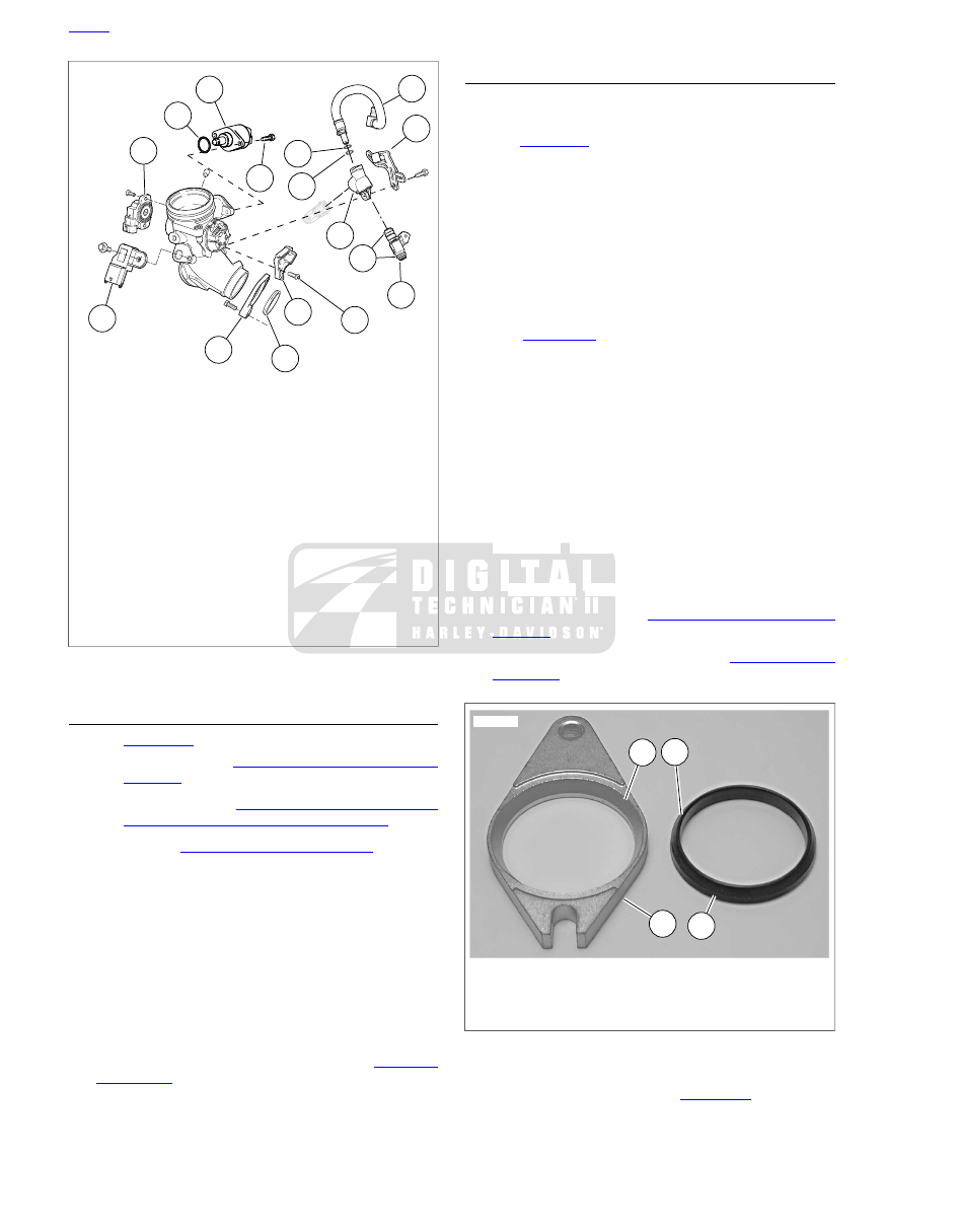
15
11
14
13
12
10
9
8
6
5
4
7
3
16
2
1
sm05421
1.
TP sensor
2.
O-ring
3.
IAC
4.
Fuel hose
5.
Nylon washer (included with hose (4))
6.
O-ring (included with hose (4))
7.
Retainer
8.
Fuel rail
9.
O-ring (4) (included in hardware and o-ring kit)
10. Fuel injector (2)
11. Screw
12. Throttle cable bracket
13. Intake seal
14. Mounting flange
15. TMAP sensor
16. Screw, IAC (2)
Figure 4-52. Induction Module
ASSEMBLY
1.
. Install the following assemblies:
a.
TP Sensor. See
b.
TMAP sensor. See
ABSOLUTE PRESSURE (TMAP) SENSOR
c.
IAC. See
.
NOTE
Do not install IAC mounting screw on throttle wheel side of
induction module until cable bracket is installed in the next
step. Install other IAC mounting screw but do not tighten at this
time.
2.
Install cable bracket (12) onto induction module. Apply
Loctite Threadlocker 243 (blue) to the threads of screw
(11). Install screw finger-tight. Then tighten both IAC
mounting screws to 60 in-lbs (6.8 Nm). Tighten screw
(11) to 60 in-lbs (6.8 Nm).
3.
Install fuel injectors, fuel rail and fuel hose. See
.
INSTALLATION
1.
Make sure the two left side mounting screws are installed
two or three turns into the heads.
2.
. Install mounting flanges (3) on induction
module with counterbore (1) facing toward the engine.
3.
Place a new seal (4) into each mounting flange with the
beveled edge (2) facing the mounting flange counterbore.
Rotate the flanges so the slotted mounting hole is on the
same side as the IAC solenoid.
NOTE
When induction module is positioned on manifold mounting
screws, be sure the flanges are installed correctly on the
manifold. Also be sure the rubber seals are in place.
4.
. Place induction module assembly in
position between engine heads. Slide open slotted ends
of mounting flanges under heads of two mounting screws
on left side of engine.
5.
While holding induction module assembly in place, install
two mounting screws (3) into remaining mounting flange
holes. Tighten all four screws finger-tight.
6.
Tighten all four mounting screws to 96-120 in-lbs (10.9-
13.6 Nm).
7.
Inspect o-rings on flare fittings (2) and replace as neces-
sary. Install flare fittings in cylinder heads and tighten to
22-26 ft-lbs (29.8-35.3 Nm).
8.
Connect oil line flare nuts (1) to flare fittings (2) and tighten
to 13-17 ft-lbs (17.6-23.0 Nm).
9.
Install throttle cables. See
10. Adjust throttle and idle cables. See
3
4
1
2
sm05423
1.
Beveled counterbore
2.
Beveled edge
3.
Mounting flange
4.
Tapered seal
Figure 4-53. Mounting Flange and Seal
11. California models only: See
. Install purge
hose onto fitting (8) on induction module (1).
4-36 2009 Sportster Service: Fuel System