Harley Davidson 2005 touring models. Service repair manual - page 30
HOME
8.
Slide electrical bracket onto studs at side of battery box.
Be sure that conduit is properly routed on inboard side of
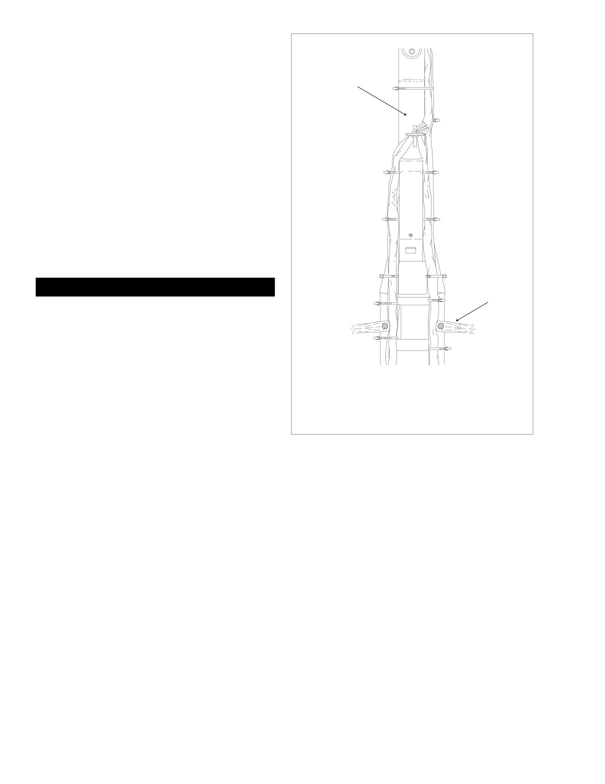
A = Anchored
electrical bracket or wires may be pinched during instal-
lation. Install flange nuts and tighten to
36-48 in-lbs
Frame
(4.1-5.4 Nm).
Backbone
9.
Install ignition control module connector [10].
10. Mate pin and socket halves of main harness connector
1 A
[8]. Install connector into slot of electrical bracket. See
Figure 8-182.
11. Verify that protective plug is installed in data link connec-
tor [91]. With the plug side down and in contact with tab,
2 A
position connector between arms on electrical bracket.
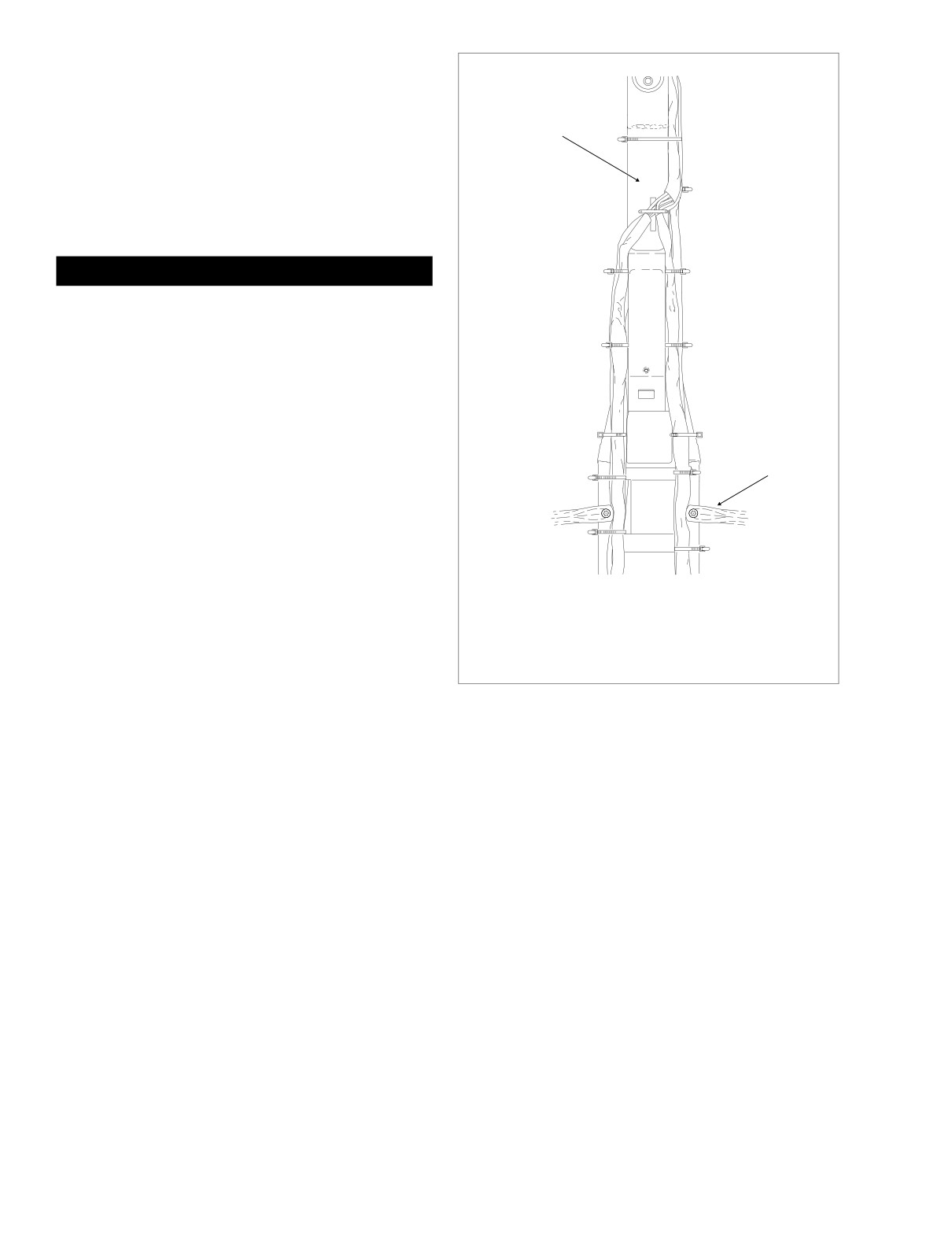
12. Tighten cable straps securing ignition harness to right
side of frame backbone, upper frame tube and other wire
harness bundles. Cut any excess cable strap material.
3 A
13. Place battery in battery box, terminal side forward.
Rotate hold-down clamp so that lip (with rubber pad)
rests on edge of battery and tighten clamp bolt.
4 A
1WARNING
Saddlebag
Guard
Always connect the positive battery cable first. If the
positive cable should contact ground with the negative
cable installed, the resulting sparks may cause a battery
explosion producing personal injury and/or property
damage.
f2225x8x
14. Insert bolt through battery positive cable
(red) into
threaded hole of battery positive (+) terminal. Tighten
1
Captures ignition harness only. ANCHORED.
bolt to 60-96 in-lbs (6.8-10.9 Nm).
2
3
4 Captures main harness, audio harness (FLHTCUI only),
ignition harness and conduit to fuel tank harness (all
15. Install fuel tank. See Section 4.7 FUEL TANK (CARBU-
models except FLHR/C/S). ANCHORED.
RETED), INSTALLATION
(AFTER COMPLETE
REMOVAL), FLHT/C or FLHR/S.
Figure 8-186. Remove/Install Cable Straps
16. Align barbed studs in side cover with grommets in frame
downtubes and push firmly into place
(no tools
required).
17. Install right side saddlebag. See Section 2.25 SADDLE-
BAG, INSTALLATION.
18. Start motorcycle and verify proper operation without set-
ting trouble codes.
8-150
2005 Touring: Electrical
HOME
EFI HARNESS (FUEL INJECTED)
f2183x8x
REMOVAL
1. Remove fuel tank. See Section 9.4 FUEL TANK (FUEL
INJECTED), COMPLETE REMOVAL, FLHT/C/U/I,
FLTRI, or FLHR/C/S/I.
1
2. Remove air cleaner and backplate. See Section 4.5 AIR
CLEANER, REMOVAL.
3. Unthread bolt and remove battery positive cable (red)
from battery positive
(+) terminal.
(Battery negative
cable already removed under FUEL TANK, COMPLETE
REMOVAL.)
4. Using a T40 TORX drive head, loosen bolt to move lip of
hold-down clamp off edge of battery. Remove battery
from battery box.
2
5. Remove right side saddlebag. See Section 2.25 SAD-
DLEBAG, REMOVAL.
6. Gently pull side cover from frame downtubes (no tools
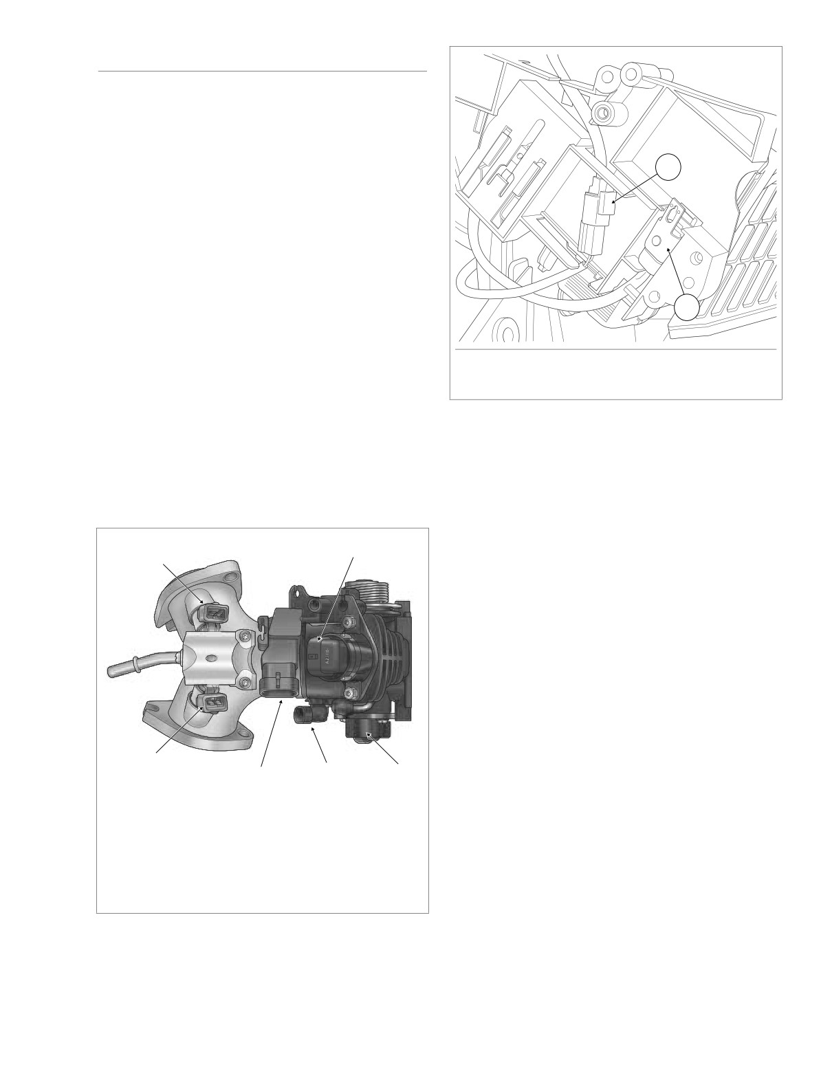
1. Vehicle Speed Sensor [65]
required).
2. P&A Security Siren [142]
NOTE
Figure 8-188. Electrical Bracket (Inboard Side)
Draw all EFI wire harness connectors to right side of motor-
cycle as they are disconnected.
8.
Remove idle air control connector [87] and manifold
7.
Carefully cut five cable straps to free EFI wire harness
absolute pressure sensor connector [80]. Pull external
from right side of frame backbone, upper frame tube and
latch(es) outward and use rocking motion to separate
other wire harness bundles. See Figure 8-191.
pin and socket halves. See Figure 8-187.
9.
Depress wire form to remove front fuel injector connec-
tor [84] and rear fuel injector connector [85].
[87A]
[84A]
Front
10.
Remove throttle position sensor connector
[88] and
intake air temperature sensor connector [89].
11.
Moving to left side of motorcycle, remove ignition coil
connector [83] from left side of ignition coil.
12.
Pull back boot to reveal engine temperature sensor con-
nector [90] at back of front cylinder. Pull external latch
outward and remove connector. Cut cable strap to
release conduit from horn bracket.
13.
Returning to right side of motorcycle, depress external
latch and remove ECM connector [78].
14.
Gently pull on data link connector [91] to disengage from
[85A]
[89A]
[88A]
arms on electrical bracket.
[80A]
15.
Locate painted white dot on inboard side of fuse block
[80A] Manifold Absolute Pressure Sensor
[119]. Pressing on dot, gently tug on conduit to release
[84A] Front Fuel Injector
tabs on fuse block from slots in bracket.
[85A] Rear Fuel Injector
16.
Pull main harness connector [8] from slot in electrical
[87A] Idle Air Control
bracket. Depress external latches and use a rocking
[88A] Throttle Position Sensor
motion to separate pin and socket halves.
[89A] Intake Air Temperature Sensor
f2162x9x
17.
Remove two flange nuts to release electrical bracket
from studs on side of battery box.
Figure 8-187. Induction Module Assembly (Top View)
2005 Touring: Electrical
8-151
HOME
INSTALLATION
8321
1.
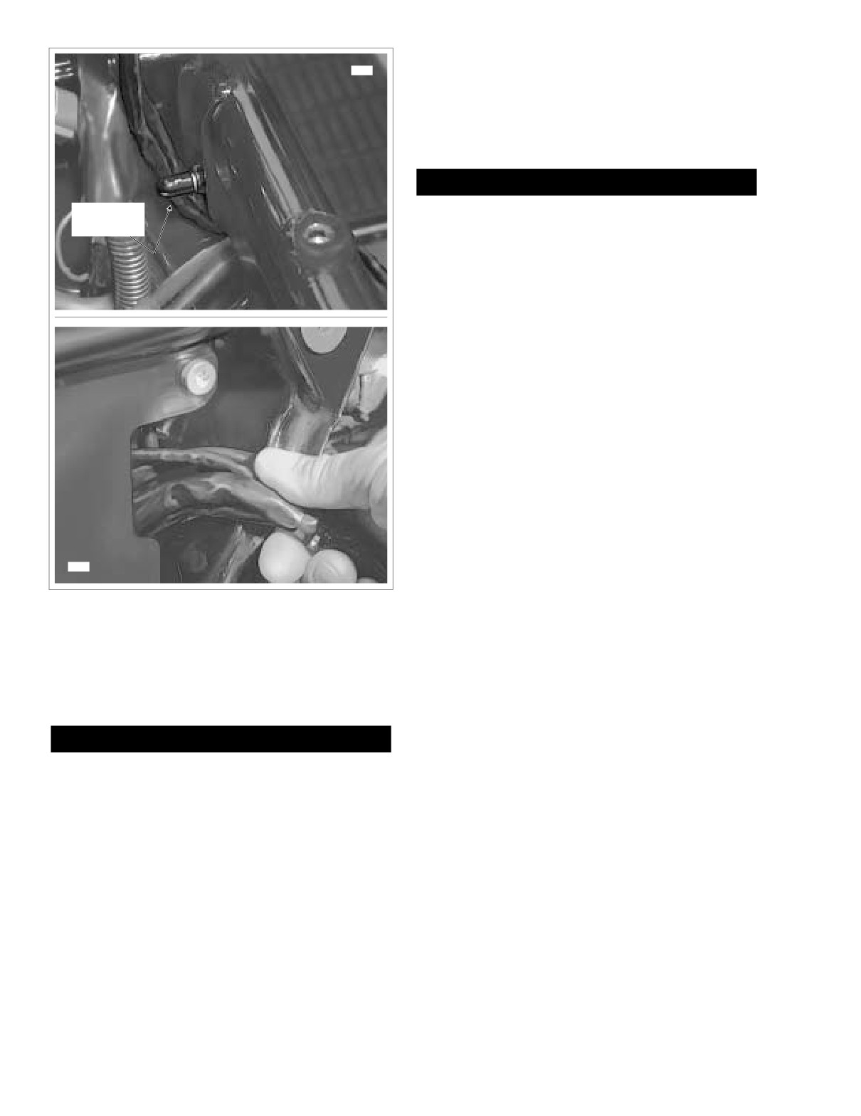
Standing on right side of vehicle, carefully feed sensor
connectors and conduit through opening into battery
box. See lower frame of Figure 8-189. Pull up on har-
ness and tuck conduit into space in front of the battery
box TORX screw.
CAUTION
Rubber
Damage to wires can result in electrical problems. Be
Boot
sure that rubber boot is present on threaded end of bat-
tery box TORX screw. Replace rubber boot if absent or
damaged. See upper frame of Figure 8-189.
2.
Draw sensor connectors and conduit up along right side
of frame backbone just below the main wire harness
bundle.
3.
Loosely install five new cable straps to secure EFI wire
harness to right side of frame backbone, upper frame
tube and other wire harness bundles. See Figure 8-191.
4.
Install front fuel injector connector
[84] and rear fuel
injector connector [85]. See Figure 8-187.
5.
Install manifold absolute pressure sensor connector [80]
and idle air control connector [87].
6.
Install intake air temperature sensor connector [89] and
throttle position sensor connector [88].
7.
Feed ignition coil and engine temperature sensor con-
nectors to left side of vehicle, routing the first in front of
the top engine stabilizer link, the latter to the rear.
8319
8.
Install ignition coil connector [83] onto left side of ignition
coil.
Figure 8-189. Remove EFI Harness From Vehicle
9.
Install engine temperature sensor connector [90] at back
of front cylinder. Pull boot over sensor to keep out dirt
and debris. Install new cable strap to secure connector
18. On inboard side of electrical bracket, disconnect vehicle
conduit to horn bracket.
speed sensor connector [65]. Depress button on socket
10.
Mate pin and socket halves of vehicle speed sensor con-
housing and pull apart pin and socket halves. See Fig-
nector [65].
ure 8-188.
11.
Install security siren connector [142] and vehicle speed
sensor connector
[65] on inboard side of electrical
CAUTION
bracket as shown in Figure 8-188. Be sure that conduit
and cables are properly routed or wires may be pinched
Damage to wires can result in electrical problems. Be
during installation.
sure that rubber boot is present on threaded end of bat-
12.
Slide electrical bracket onto studs at side of battery box.
tery box TORX screw. Replace rubber boot if absent or
Install flange nuts and tighten to 36-48 in-lbs (4.1-5.4
damaged. See upper frame of Figure 8-189.
Nm).
19. Note that harness conduit runs forward of the front bat-
13.
Mate pin and socket halves of main harness connector
tery box TORX screw. Pull conduit to the rear of the
[8]. Install connector into slot of electrical bracket.
screw, and then draw sensor connectors and conduit
14.
Engage tabs on fuse block [119] with slots in electrical
down right side of frame backbone into battery box.
bracket. Slide fuse block up into cavity. Gently tug on
20. Pull connectors and conduit out through opening at side
conduit to verify that fuse block is locked in place.
of battery box to remove harness from vehicle. See
15.
Install ECM connector
[78]. Push connector halves
lower frame of Figure 8-189.
together until latch clicks.
8-152
2005 Touring: Electrical
HOME
[78B]
[65B]
[8A]
ECM Power
[91A]
Fuse
Fuel Pump
Fuse
Spare
[119B]
Fuse
EFI System
Relay
[88B]
[90B]
[89B]
[80B]
Rubber
Boot
[85B]
[84B]
[87B]
[8A]
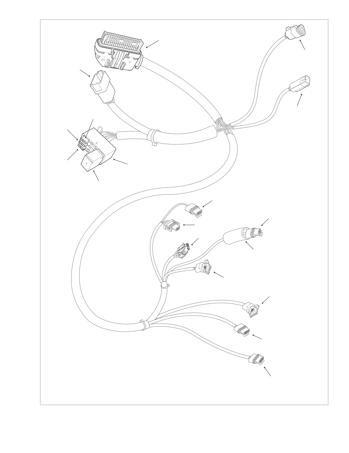
Main Harness
[65B]
Vehicle Speed Sensor
[78B] Electronic Control Module (ECM)
[80B] Manifold Absolute Pressure Sensor
[88B] Throttle Position Sensor
[83B] Ignition Coil
[89B] Intake Air Temperature Sensor
[84B] Front Injector
[90B] Engine Temperature Sensor
[83B]
[85B] Rear Injector
[91A] Data Link
[87B] Idle Air Control
[119B] EFI Fuse Block
f2224x9x
Figure 8-190. EFI Wire Harness Connectors
2005 Touring: Electrical
8-153
HOME
16. Verify that protective plug is installed in data link connec-
tor [91]. With the plug side down and in contact with tab,
A = Anchored
position connector between arms on electrical bracket.
Frame
17. Tighten five cable straps securing EFI wire harness to
Backbone
right side of frame backbone, upper frame tube and
other wire harness bundles. Cut any excess cable strap
material.
1 A
18. Place battery in battery box, terminal side forward.
Rotate hold-down clamp so that lip (with rubber pad)
rests on edge of battery and tighten clamp bolt.
1WARNING
2 A
Always connect the positive battery cable first. If the
positive cable should contact ground with the negative
cable installed, the resulting sparks may cause a battery
3 A
explosion producing personal injury and/or property
damage.
19. Insert bolt through battery positive cable
(red) into
threaded hole of battery positive (+) terminal. Tighten
bolt to 60-96 in-lbs (6.8-10.9 Nm).
4 A
Saddlebag
20. See Section
9.4 FUEL TANK
(FUEL INJECTED),
Guard
INSTALLATION
(AFTER COMPLETE REMOVAL),
FLHT/C/U/I, FLTRI, or FLHR/C/S/I
21. Install backplate and air cleaner. See Section 4.5 AIR
CLEANER, INSTALLATION.
f2225x8x
22. Align barbed studs in side cover with grommets in frame
downtubes and push firmly into place
(no tools
required).
1
Captures EFI harness only (front injector, idle air control
and ignition coil conduit). ANCHORED.
23. Install right side saddlebag. See Section 2.25 SADDLE-
2
3
4 Captures main harness, audio harness (FLHTCUI only),
BAG, INSTALLATION.
EFI harness and conduit to fuel tank harness (all models
except FLHR/C/S). ANCHORED.
24. Start vehicle and verify proper operation without setting
trouble codes.
Figure 8-191. Remove/Install Cable Straps
8-154
2005 Touring: Electrical
Table Of Contents
SUBJECT
PAGE NO.
9.1 Specifications
9-1
9.2 Electrical Bracket Assembly
9-3
9.3 Sensors
9-6
9.4 Fuel Tank (Fuel Injected)
9-8
9.5 Induction Module Assembly
9-27
NOTE
See the 2005 ELECTRICAL DIAGNOSTIC MANUAL
(Part No. 99497-05) for all SYSTEM DIAGNOSIS and
ELECTRICAL TROUBLESHOOTING information.
FUEL INJECTION
9
HOME
SPECIFICATIONS
9.1
EFI FUSES
TORQUE VALUES
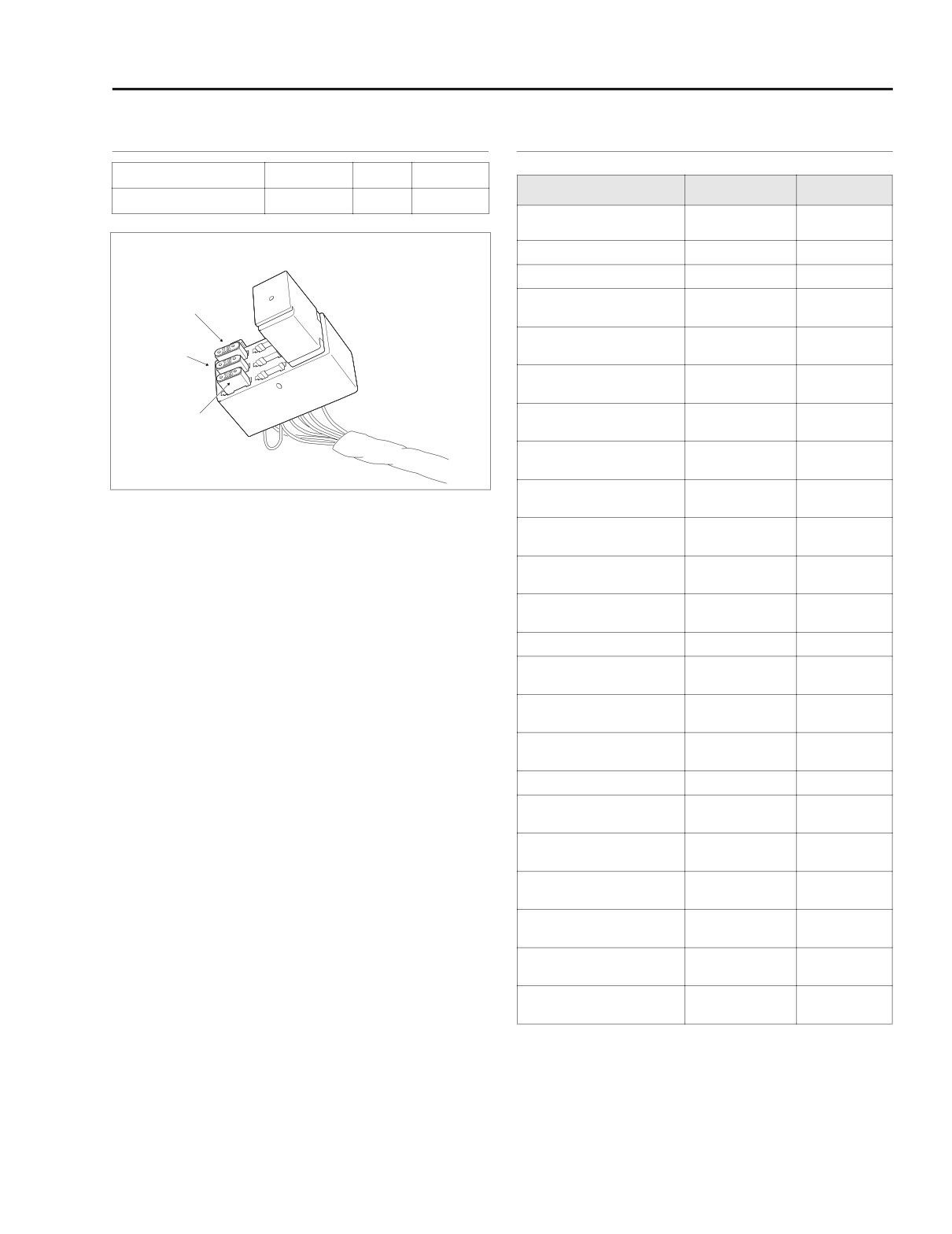
Fuel Pump
15
Blue
Blade
Item
ft/in-lbs
Nm
ECM Power
15
Blue
Blade
Battery hold-down clamp
15-20 ft-lbs
20-27 Nm
TORX bolt
Battery cable bolt
60-96 in-lbs
6.8-10.9 Nm
ECM socket screws
50-60 in-lbs
5.7-6.8 Nm
EFI System
Relay
Electrical bracket flange
Spare
36-48 in-lbs
4.1-5.4 Nm
nuts
Crank position
90-120 in-lbs
10.2-13.6 Nm
Fuel Pump
sensor screw
Engine temperature
120-180 in-lbs
13.6-20.3 Nm
sensor
Fuel tank rear mounting
ECM Power
15-20 ft-lbs
20-27 Nm
bolt
f2223x9x
Fuel tank front mounting
15-20 ft-lbs
20-27 Nm
bolts
Fuel tank canopy TORX
18-24 in-lbs
2.0-2.7 Nm
Figure 9-1. EFI Fuses (Under Right Side Cover)
screws
Fuel level sender TORX
25-35 in-lbs
2.8-4.0 Nm
screw
Fuel supply line
22-26 ft-lbs
29.8-35.3 Nm
quick-connect fitting
Fairing lower U-bolt
35-40 in-lbs
4.0-4.5 Nm
retainer locknuts
Fairing lower cap screws
10-15 in-lbs
1.1-1.7 Nm
Intake manifold to throttle
27-33 in-lbs
3.1-3.7 Nm
body TORX screws
Intake flange adapter
96-144 in-lbs
10.9-16.3 Nm
screws
Exhaust flange adapter
100-120 in-lbs
11.3-13.6 Nm
nuts
Fuel rail TORX screws
27-33 in-lbs
3.0-3.7 Nm
Fuel supply tube clamp
27-33 in-lbs
3.0-3.7 Nm
TORX screw
Intake air temperature
12 in-lbs
1.4 Nm
sensor TORX screws
Throttle position sensor
27-33 in-lbs
3.0-3.7 Nm
TORX screws
Throttle cable bracket
27-33 in-lbs
3.0-3.7 Nm
side TORX screw
Idle air control flange
25 in-lbs
2.8 Nm
screws
Console mounting bolt
50-90 in-lbs
5.7-10.2 Nm
acorn nut
2005 Touring: Fuel Injection
9-1
HOME
NOTES
9-2
2005 Touring: Fuel Injection
HOME
ELECTRICAL BRACKET ASSEMBLY
9.2
GENERAL
DATA LINK CONNECTOR
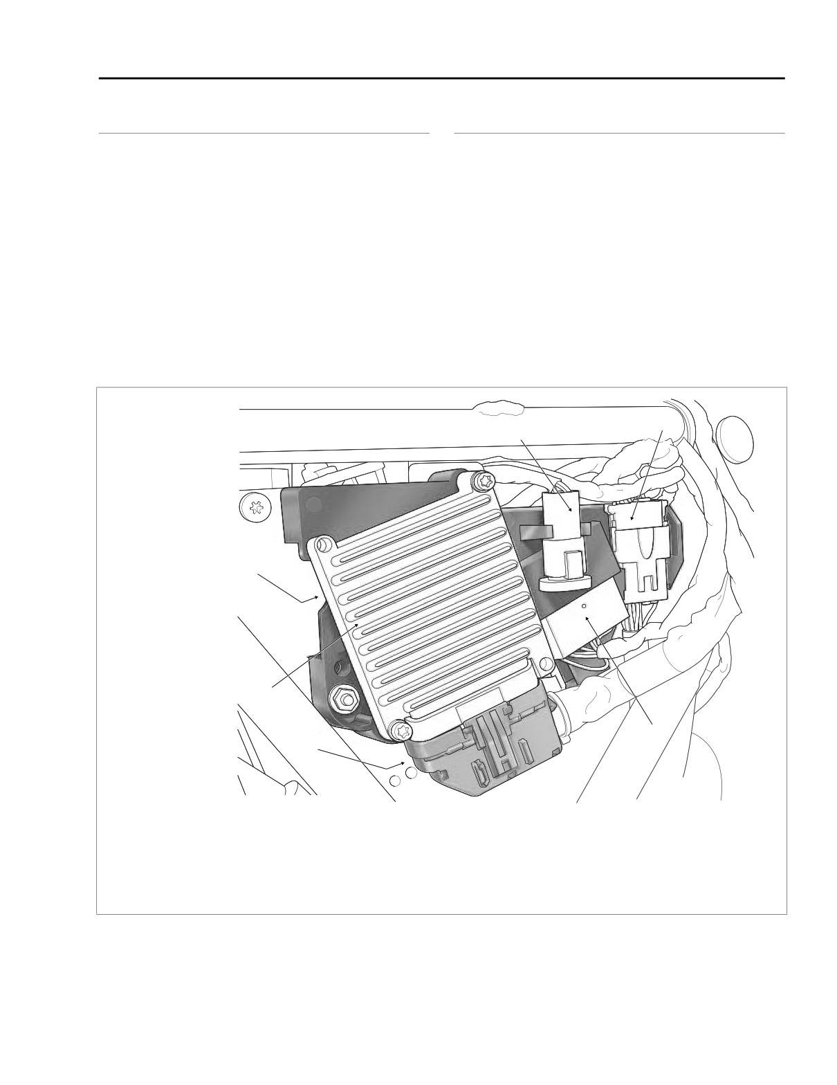
See Figure 9-2. The electrical bracket assembly is mounted
SETTING ENGINE IDLE SPEED
beneath the side cover on the right side of the vehicle. The
electrical bracket assembly carries the following components:
NOTE
● Data Link Connector
Engine idle speed can only be set using DIGITAL TECHNI-
CIAN (Part No. HD-44750). Do not tamper with the throttle
● Main Harness to EFI Harness Connector
stop screw as it will not permanently change idle speed.
● ECM Power Fuse/Fuel Pump Fuse
1.
Turn the ignition/light key switch to OFF.
● EFI System Relay
2.
Remove right side saddlebag. See Section 2.25 SAD-
● Electronic Control Module (ECM)
DLEBAG, REMOVAL.
● Vehicle Speed Sensor Connector
3.
Gently pull side cover from frame downtubes (no tools
● Optional Security Siren Connector
required).
2
1
6,7
5
3
4
f1917x9x
1.
Data Link Connector [91]
2.
Main Harness Connector [8]
5.
Electronic Control Module (ECM)
3.
Fuse Block (ECM Power Fuse, Fuel Pump
6.
Vehicle Speed Sensor Connector [65]
Fuse, EFI System Relay)
(Under Bracket)
4.
Electronic Control Module Connector [78]
7.
P&A Security Siren Connector [142] (Under Bracket)
Figure 9-2. Electrical Bracket Assembly
2005 Touring: Fuel Injection
9-3
HOME
INSTALLATION
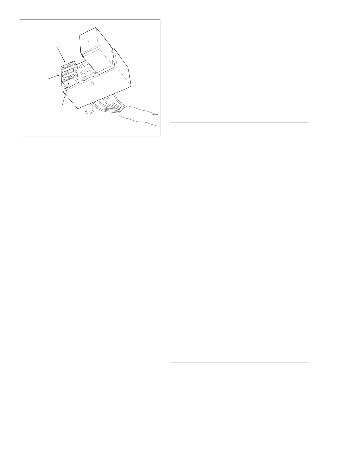
EFI System Relay
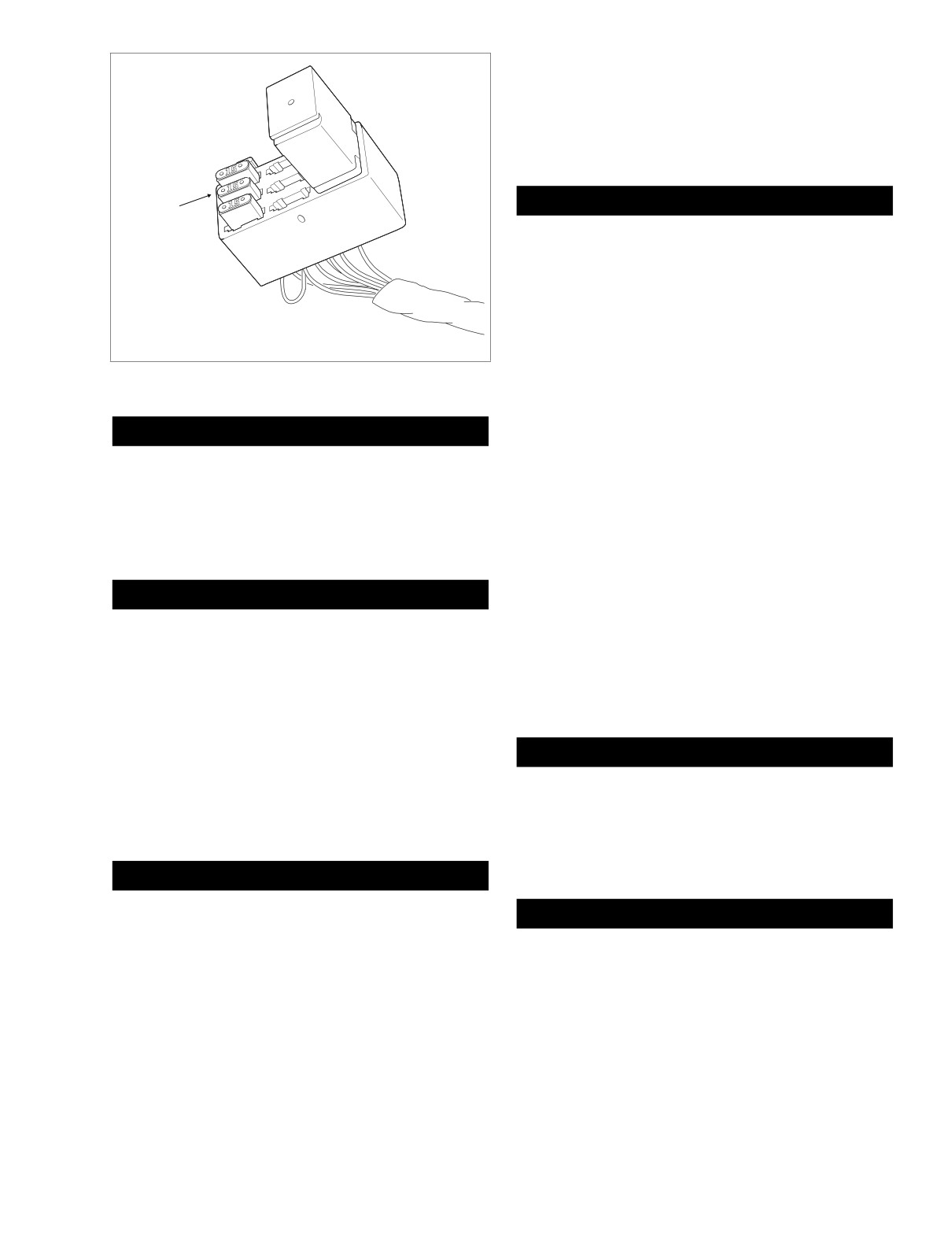
1. Install relay in slots of fuse block. See Figure 9-3.
2. Engage tabs on fuse block with slots in bracket. Slide
Spare
fuse block up into cavity. Gently tug on conduit to verify
that fuse block is locked in place.
3. Align barbed studs in side cover with grommets in frame
downtubes and push firmly into place
(no tools
required).
Fuel
Pump
4. Install right side saddlebag. See Section 2.25 SADDLE-
BAG, INSTALLATION.
f2223x9x
ECM Power
EFI FUSES
REMOVAL
Figure 9-3. EFI Fuse Block
1. Remove right side saddlebag. See Section 2.25 SAD-
DLEBAG, REMOVAL.
2. Gently pull side cover from frame downtubes (no tools
4.
Gently pull on data link connector [91] to disengage from
required).
arms on electrical bracket. See Figure 9-2.
3. Locate painted white dot on inboard side of fuse block.
5.
Remove rubber protective plug from data link connector.
Pressing on dot, gently tug on conduit to release tabs on
fuse block from slots in bracket.
6.
See DIGITAL TECHNICIAN (Part No. HD-44750) or the
TOURING MODELS ELECTRICAL DIAGNOSTIC MAN-
4. Pull fuses from slots in fuse block and inspect for dam-
UAL to use the data link connector for system diagnosis
age. Replace fuse if the element is burned or broken.
and electrical troubleshooting.
Automotive type ATO fuses are used. See Figure 9-3.
7.
Install protective plug in data link connector.
NOTE
While a spare 15 amp fuse is located in the EFI fuse block,
8.
With the plug side down and in contact with tab, position
one extra 10 amp and 15 amp fuse are also located in the
connector between arms on electrical bracket.
system fuse block cover. See Section 8.3 SYSTEM FUSES
9.
Align barbed studs in side cover with grommets in frame
for more information.
downtubes and push firmly into place
(no tools
required).
INSTALLATION
10.
Install right side saddlebag. See Section 2.25 SADDLE-
BAG, INSTALLATION.
1.
Insert fuse in the appropriate slot. See Figure 9-3.
2.
Engage tabs on fuse block with slots in bracket. Slide
fuse block up into cavity. Gently tug on conduit to verify
that fuse block is locked in place.
EFI SYSTEM RELAY
3.
Align barbed studs in side cover with grommets in frame
downtubes and push firmly into place
(no tools
required).
REMOVAL
4.
Install right side saddlebag. See Section 2.25 SADDLE-
BAG, INSTALLATION.
1. Remove right side saddlebag. See Section 2.25 SAD-
DLEBAG, REMOVAL.
2. Gently pull side cover from frame downtubes (no tools
ELECTRONIC CONTROL MODULE
required).
3. Locate painted white dot on inboard side of fuse block.
Pressing on dot, gently tug on conduit to release tabs on
REMOVAL
fuse block from slots in bracket.
1.
Remove right side saddlebag. See Section 2.25 SAD-
4. Pull relay from slots in fuse block. See Figure 9-3.
DLEBAG, REMOVAL.
9-4
2005 Touring: Fuel Injection
HOME
2. Gently pull side cover from frame downtubes (no tools
required).
f2183x8x
3. Depress external latch and use rocking motion to
remove ECM connector [78]. See Figure 9-2.
4. Remove two socket screws to detach ECM from electri-
cal bracket.
1
INSTALLATION
1. Align holes in ECM with those in electrical bracket.
Install two socket screws and tighten to 50-60 in-lbs
(5.7-6.8 Nm). See Figure 9-2.
2. Install ECM connector
[78]. Push connector halves
together until latch clicks.
2
3. Align barbed studs in side cover with grommets in frame
downtubes and push firmly into place
(no tools
required).
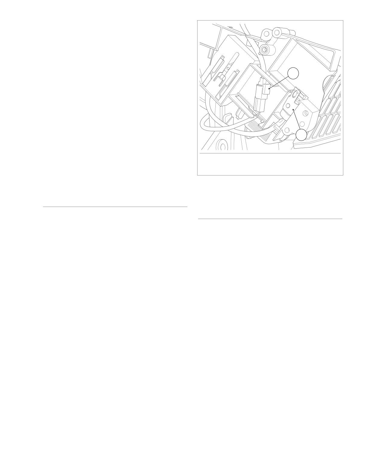
1. Vehicle Speed Sensor [65]
4. Install right side saddlebag. See Section 2.25 SADDLE-
2. P&A Security Siren [142]
BAG, INSTALLATION.
Figure 9-4. Electrical Bracket (Inboard Side)
SECURITY SIREN CONNECTOR
EFI HARNESS
REMOVAL
For removal and installation instructions, see Section 8.32
1. Remove right side saddlebag. See Section 2.25 SAD-
WIRING HARNESSES
AND
CABLES,
EFI
HARNESS
DLEBAG, REMOVAL.
(FUEL INJECTED).
2. Gently pull side cover from frame downtubes (no tools
required).
3. Remove two flange nuts to release electrical bracket
from studs on side of battery box. See Figure 9-4.
INSTALLATION
1. Install security siren connector [142] and vehicle speed
sensor connector
[65] on inboard side of electrical
bracket as shown in Figure 9-4. Be sure that conduit and
cables are properly routed or wires may be pinched dur-
ing installation.
2.
Slide electrical bracket onto studs at side of battery box.
3. Install flange nuts on studs and tighten to 36-48 in-lbs
(4.1-5.4 Nm).
4. Align barbed studs in side cover with grommets in frame
downtubes and push firmly into place
(no tools
required).
5. Install right side saddlebag. See Section 2.25 SADDLE-
BAG, INSTALLATION.
2005 Touring: Fuel Injection
9-5
HOME
SENSORS
9.3
GENERAL
f2256x8x
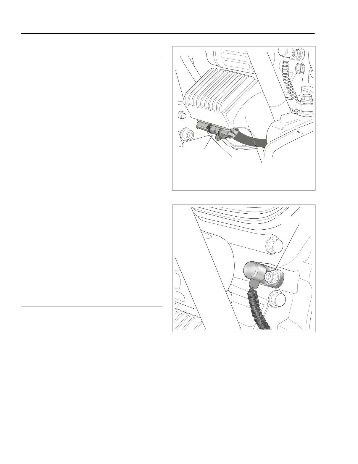
Six sensors inform the ECM of the environmental and engine
operating factors influencing fuel and spark requirements.
The sensors are as follows:
● Intake Air Temperature Sensor
● Throttle Position Sensor
● Manifold Absolute Pressure Sensor
● Bank Angle Sensor (Internal to TSM/TSSM)
● Crankshaft Position Sensor
● Engine Temperature Sensor
Stator
INTAKE AIR TEMPERATURE SENSOR
Connector [46]
See Section
9.5 INDUCTION MODULE ASSEMBLY,
Crankshaft
Position Sensor
INTAKE AIR TEMPERATURE SENSOR.
Connector [79]
THROTTLE POSITION SENSOR
Figure 9-5. Voltage Regulator (Left Side View)
See Section
9.5 INDUCTION MODULE ASSEMBLY,
THROTTLE POSITION SENSOR.
f2217x8x
MANIFOLD ABSOLUTE PRESSURE
Socket Screw
SENSOR
See Section 9.5 INDUCTION MODULE ASSEMBLY, MANI-
FOLD ABSOLUTE PRESSURE SENSOR.
BANK ANGLE SENSOR
See Section 8.17 TURN SIGNAL/SECURITY MODULE.
CRANKSHAFT POSITION SENSOR
REMOVAL
1.
Remove maxi-fuse. See Section 8.3 SYSTEM FUSES,
MAXI-FUSE, REMOVAL.
Figure 9-6. Remove Sensor Mount Socket Screw
2.
Locate crankshaft position sensor connector
[79],
2-
place Mini-Deutsch, fixed to bracket at bottom of voltage
regulator. See Figure 9-5.
5.
Remove allen head socket screw to free crankshaft posi-
3.
Push connector toward right side of motorcycle to disen-
tion sensor mount from front left side of crankcase. Pull
gage small end of slot on attachment clip from T-stud on
sensor from bore. See Figure 9-6.
bracket. Lift connector off T-stud.
6.
Pull sensor to draw convoluted tubing and connector out
4.
Depress button on socket terminal side and pull apart
from under voltage regulator.
pin and socket halves.
9-6
2005 Touring: Fuel Injection
HOME
INSTALLATION
O-Ring
1. Hand start threaded end of new temperature sensor into
cylinder head bore.
2. Slide 3/4 inch deepwell socket over sensor body hex and
tighten to 120-180 in-lbs (13.6-20.3 Nm).
3. Install engine temperature sensor connector
[90],
2-
place Packard, at back of front cylinder.
4. Pull boot over sensor to keep out dirt and debris.
5. Install maxi-fuse. See Section
8.3 SYSTEM FUSES,
f2321x8x
MAXI-FUSE, INSTALLATION.
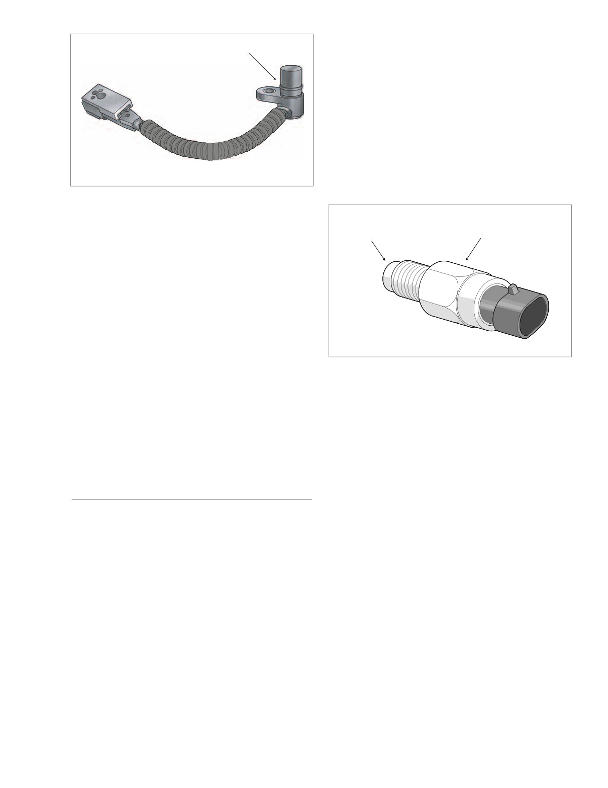
Figure 9-7. Crankshaft Position Sensor
Sensor
Body Hex
INSTALLATION
Thermistor
1. Install new O-ring on sensor body if missing, distorted,
pinched or otherwise damaged. Apply a thin film of clean
H-D 20W50 engine oil to O-ring before installation.
2. Push sensor into bore aligning hole in sensor mount with
hole in spot face. Install allen head socket screw and
tighten to 90-120 in-lbs (10.2-13.6 Nm). See Figure 9-6.
3. Route connector and convoluted tubing under front
f1699x9x
engine stabilizer link to underside of voltage regulator.
4. Mate pin and socket halves of crankshaft position sensor
Figure 9-8. Engine Temperature Sensor
connector [79]. See Figure 9-5.
5. Place large end of slot on attachment clip over T-stud on
bracket. Push connector toward left side of motorcycle to
engage small end of slot.
6. Install maxi-fuse. See Section
8.3 SYSTEM FUSES,
MAXI-FUSE, INSTALLATION.
ENGINE TEMPERATURE SENSOR
REMOVAL
1. Remove maxi-fuse. See Section 8.3 SYSTEM FUSES,
MAXI-FUSE, REMOVAL.
2. On left side of motorcycle, pull back boot at back of front
cylinder to reveal engine temperature sensor connector
[90], 2-place Packard.
3. Pull external latch outward and use rocking motion to
remove connector.
4. Slide a 3/4 inch deepwell socket over the sensor body
hex and turn counter-clockwise to loosen. See Figure 9-
8. When sensor turns easily, pull out the deepwell socket
and remove sensor by hand.
2005 Touring: Fuel Injection
9-7
HOME
FUEL TANK (FUEL INJECTED)
9.4
● Fuel Filter Canister
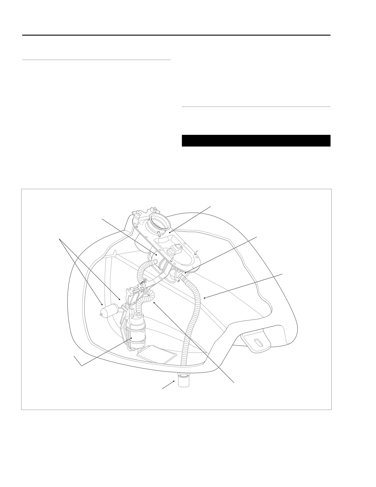
GENERAL
● Fuel Level Sender
See Figure 9-9. The fuel pump, fuel filter canister, fuel pres-
● Fuel Supply Check Valve
sure regulator, and fuel level sender are attached to the can-
opy for easy removal and installation. The act of raising the
canopy automatically removes these items, thereby eliminat-
ing those tasks which used to be performed by reaching
COMPLETE REMOVAL
inside the fuel tank. This arrangement minimizes the possibil-
ity of dropping or losing parts inside the tank, or adding con-
taminants (such as grease and oil) to the fuel supply.
FLHT/C/U/I, FLTRI
The fuel tank assembly consists of the following components:
● Fuel Tank
1WARNING
● Canopy
Gasoline is extremely flammable and highly explosive.
● Fuel Pump
When servicing the fuel system, do not smoke or allow
● Fuel Pressure Regulator
open flame or sparks in the vicinity. Inadequate safety
precautions could result in death or serious injury.
Canopy
Fuel Filter
Canister
Fuel Level
Sender
Fuel Pressure
and Float
Regulator
In-tank Tubing
(Fuel Pressure Regulator
to Supply Fitting)
Fuel Pump
In-tank Tubing
Supply Fitting
(Fuel Pump to Filter Canister)
f1969x9x
(Check Valve)
Figure 9-9. Fuel Tank Assembly (FLHT/C/U/I, FLTRI)
9-8
2005 Touring: Fuel Injection
HOME
a. Remove the 15 amp fuel pump fuse. See Figure 9-
10. If necessary, see Section
9.2 ELECTRICAL
BRACKET ASSEMBLY, EFI FUSES, REMOVAL.
b. Start the engine and allow the vehicle to run.
c. When the engine stalls, operate starter for 3 sec-
onds to remove remaining fuel from fuel lines.
Fuel
1WARNING
Pump
To protect against shock and accidental start-up of vehi-
cle, disconnect the negative battery cable before pro-
ceeding. Inadequate safety precautions could result in
death or serious injury.
4.
Unthread bolt and remove battery negative cable (black)
from battery negative (-) terminal.
f2223x9x
5.
Carefully cut anchored cable strap securing main har-
Figure 9-10. EFI Fuse Block
ness bundles, console pod conduit (Ultra models only),
fuel level sender/fuel pump conduit, and fuel vapor vent
tube to left side of frame backbone.
1WARNING
6.
Open fuel door on console. Remove two Allen head
screws inboard of rubber bumpers. These screws secure
Gasoline will drain from the crossover hose when dis-
console to clip nuts on the canopy bracket.
connected from the fuel tank. Thoroughly wipe up any
7.
Remove Allen head screw to detach flange at rear of
spilled fuel immediately. Dispose of rags in a suitable
console from clip nut on fuel tank weldment.
manner. Gasoline is extremely flammable and highly
explosive. Inadequate safety precautions could result in
8.
Lay a clean shop towel on forward part of rear fender.
death or serious injury.
9.
Remove filler cap from neck of fuel tank. Remove con-
sole and lay upside down on shop towel. Reinstall filler
cap.
CAUTION
10. Depress button on socket side and remove fuel level
Do not kink crossover hose or crimp shut using pliers or
sender/fuel pump connector [141], 3-place Mini-Deut-
similar tool. Damage to the rigid inner lining will occur.
sch, at top of canopy.
1. Drain fuel tank as follows:
11. Gently pry fuel vapor vent tube from fitting on filler neck
of fuel tank. Exercise caution to avoid pulling fitting from
Obtain a short section of hose with a 5/16 inch (7.9 mm) I.D.
filler neck.
Insert bolt in one end of hose and install hose clamp to
ensure that end is securely plugged. Using a side cutters, cut
clamp from one end of crossover hose beneath fuel tank.
1WARNING
Quickly replace crossover hose on fuel tank fitting with open
end of short hose while directing flow of gasoline from free
A small amount of gasoline may drain from the fuel sup-
end of crossover hose into suitable container.
ply line when disconnected from the fuel tank. Thor-
oughly wipe up any spilled fuel immediately. Dispose of
2. Remove seat. See Section 2.24 SEAT, REMOVAL.
rags in a suitable manner. Gasoline is extremely flamma-
ble and highly explosive. Inadequate safety precautions
could result in death or serious injury.
1WARNING
The gasoline in the fuel supply line downstream of the
1WARNING
fuel pump is under high pressure (58 psi). To avoid an
uncontrolled discharge or spray of gasoline, always
Exercise caution to avoid twisting the fuel supply line fit-
purge the system of high pressure gas before the fuel
ting, as any cracks in the plastic construction of the line
supply line is disconnected. Gasoline is extremely flam-
can result in gas leaks. Gas leakage can cause fire or
mable and highly explosive. Inadequate safety precau-
explosion which could result in death or serious injury.
tions could result in death or serious injury.
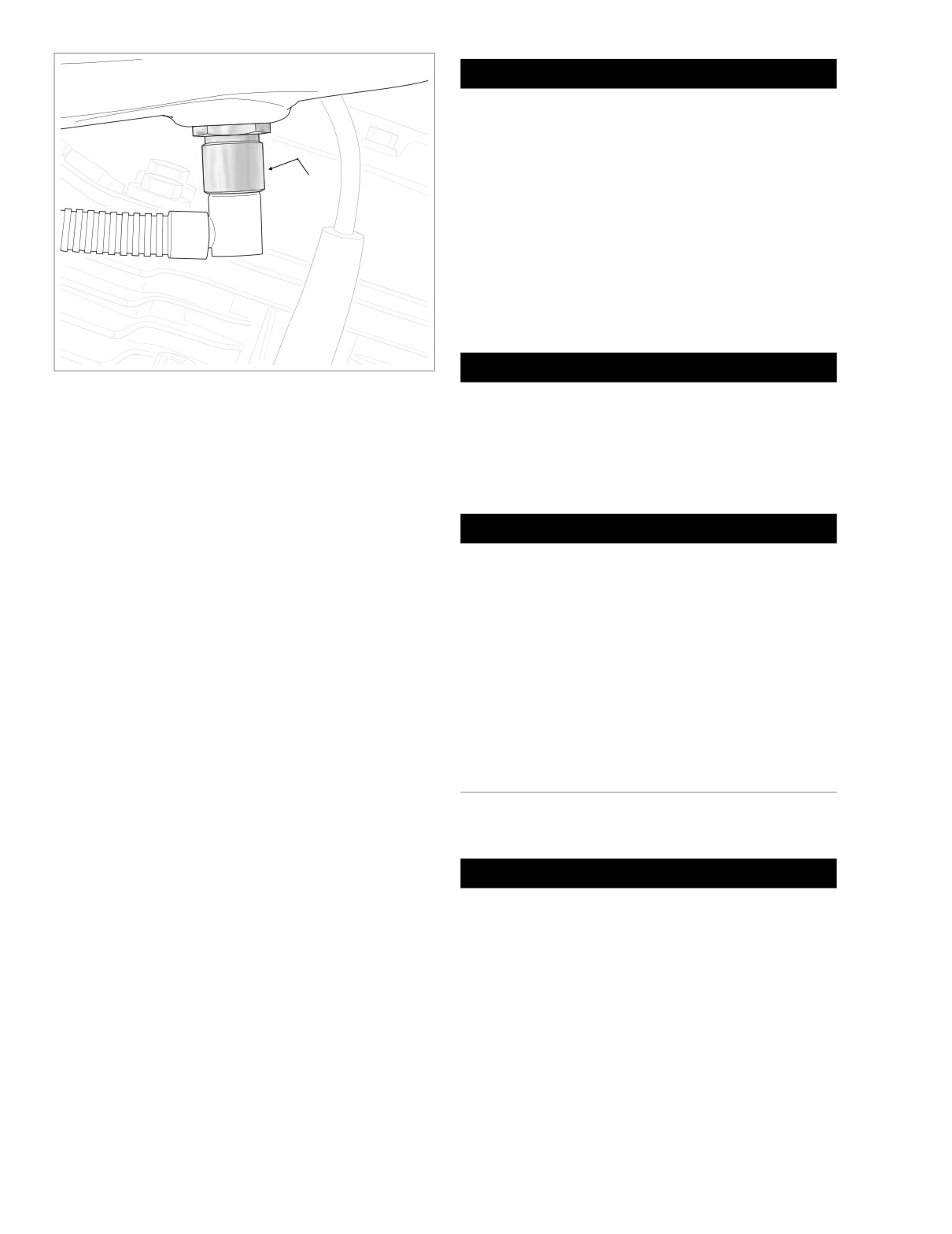
12. Locate quick-connect fitting on left side of fuel tank. Pull
3. Purge the fuel supply line of high pressure gas. Proceed
up on chrome sleeve and pull down on fuel supply line
as follows:
fitting to disconnect. See Figure 9-11.
2005 Touring: Fuel Injection
9-9
HOME
f2021x9x
Fuel
CAUTION
Tank
When removing instrument console, exercise caution to
avoid damaging speedometer unit. Wrap console in a
clean, dry shop towel to prevent damage.
6.
Secure instrument console to top of rear fender using
Chrome
bungee cords.
Sleeve
7.
Remove console mounting bolt from slot at top of can-
opy.
8.
Gently pry fuel vapor vent tube from fitting.
9.
At bottom left side of fuel tank, gently pull on convoluted
tubing to draw fuel gauge connector [117], 4-place Mul-
tilock, out of tunnel. Depress button on socket terminal
side and pull apart pin and socket halves.
1WARNING
Figure 9-11. Fuel Supply Line Fitting
A small amount of gasoline may drain from the fuel sup-
ply line when disconnected from the fuel tank. Thor-
oughly wipe up any spilled fuel immediately. Dispose of
13. Remove two fuel tank front mounting bolts (with flat
rags in a suitable manner. Gasoline is extremely flamma-
washers) from left and right side of frame. Remove bolt
ble and highly explosive. Inadequate safety precautions
(with flat washer) to free rear of fuel tank from frame
could result in death or serious injury.
backbone.
NOTE
1WARNING
The fuel tank mounting bolts have both an internal TORX
recess and an external hex, which allows them to be
Exercise caution to avoid twisting the fuel supply line fit-
removed with either a T40 TORX bit or a 1/2 inch open end/
ting, as any cracks in the plastic construction of the line
box wrench. Use of the external hex allows the front mount-
can result in gas leaks. Gas leakage can cause fire or
ing bolts to be removed without having to loosen or remove
explosion which could result in death or serious injury.
the fairing lowers, if installed.
10. Locate quick-connect fitting on left side of fuel tank. Pull
14. Remove fuel tank from vehicle.
up on chrome sleeve and pull down on fuel supply line
fitting to disconnect. See Figure 9-11.
11. Remove fuel tank from vehicle.
FLHR/C/S/I
1.
See Section 9.4 FUEL TANK (FUEL INJECTED), COM-
INSTALLATION
PLETE REMOVAL, FLHT/C/U/I, FLTRI, steps 1-4.
(AFTER COMPLETE REMOVAL)
2.
Remove two fuel tank front mounting bolts (with flat
washers) from left and right side of frame. Remove bolt
(with flat washer) to free rear of fuel tank from frame
FLHT/C/U/I, FLTRI
backbone. On FLHRSI models, removal of rear bolt also
releases instrument console bracket.
CAUTION
3.
Carefully cut anchored cable strap securing main har-
ness bundle, instrument console conduit, and fuel vapor
Exercise caution to avoid pinching the wiring harness
vent tube to left side of frame backbone.
between the fuel tank and vehicle frame. Wire damage
may result in electrical problems.
4.
Remove acorn nut from instrument console. If present,
also remove Phillips screw and large flat washer (absent
1.
Work fuel tank into position aligning front flange holes
on FLHRSI models).
with those in frame.
5.
Raise instrument console and bend back flexible clamp
2.
Slide new clamp onto free end of crossover hose. Run-
on canopy to release main harness conduit. Depress
ning hose beneath frame backbone, install hose onto fit-
button on socket side and remove fuel level sender/fuel
ting at bottom front of fuel tank
(after removing
pump connector [141], 3-place Mini-Deutsch.
temporary plug). Crimp clamp.
9-10
2005 Touring: Fuel Injection
HOME
3.
Start fuel tank front mounting bolts (with flat washers)
f2007x9x
into left and right side of frame.
Console
4. Install bolt (with flat washer) to secure rear of fuel tank to
Pod
frame backbone. Tighten bolt to 15-20 ft-lbs (20-27 Nm).
Fuel
Tank
5.
Tighten fuel tank front mounting bolts to 15-20 ft-lbs (20-
27 Nm).
1WARNING
Fuel Pump,
Fuel Level
Exercise caution to avoid twisting the fuel supply line fit-
Sender Conduit
ting, as any cracks in the plastic construction of the line
can result in gas leaks. Gas leakage can cause fire or
explosion which could result in death or serious injury.
Fuel
6. Locate quick-connect fitting on left side of fuel tank. Pull
Main
Overflow
up on chrome sleeve and insert neck of fuel supply line
Harness
Fuel Vapor
Hose
fitting. While pushing up on bottom of fitting, pull down
Bundle
Vent Tube
(To Vapor Valve)
on chrome sleeve until it “clicks” into the locked position.
1WARNING
Main
To avoid an uncontrolled discharge or spray of gasoline,
Anchored
Harness
always be sure the quick-connect fitting is properly
Console
Cable Strap
Bundle
mated. A slight tug on the fuel supply line fitting will ver-
Pod Conduit
ify this condition. Gasoline is extremely flammable and
highly explosive. Inadequate safety precautions could
FLHTCUI
result in death or serious injury.
7. Connect fuel vapor vent tube to nipple on filler neck of
f1739b9x
fuel tank.
Fuel
8. Install fuel level sender/fuel pump connector [141], 3-
Tank
place Mini-Deutsch, at top of canopy.
Console
9. Remove filler cap. Position console on canopy. Route
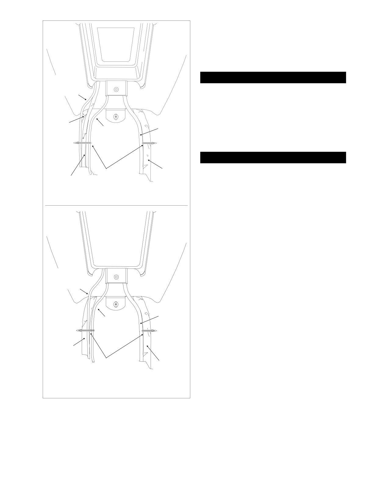
cables from beneath console as shown in Figure 9-12.
Be sure that hoses and wires are not pinched by the
console during installation. Reinstall filler cap.
Fuel Pump,
Fuel Level
10. Install Allen head screw to fasten rear flange of console
Sender Conduit
to clip nut on fuel tank weldment. Tighten screw to 25-30
in-lbs (2.8-3.4 Nm).
11. Open fuel door on console. Install two Allen head screws
Fuel
to secure front of console to clip nuts on canopy bracket.
Overflow
Alternately tighten screws to 25-30 in-lbs (2.8-3.4 Nm).
Fuel Vapor
Hose
Vent Tube
12. Snap anchor of new cable strap into hole on left side of
(To Vapor Valve)
frame backbone. Tighten cable strap capturing main har-
ness bundles, console pod conduit (Ultra models only),
Main
fuel level sender/fuel pump conduit, and fuel vapor vent
Harness
tube. See Figure 9-12. Cut any excess cable strap mate-
Bundle
rial.
Anchored
Main
Cable Strap
Harness
NOTE
Bundle
Route fuel overflow hose inboard of wire bundles on right
side of frame, but do not capture in cable straps.
FLHT/C/I, FLTRI
13. Insert bolt through battery negative cable (black) into
Figure 9-12. Console Pod Cable/Hose Routing
threaded hole of battery negative (-) terminal. Tighten
(Top View)
bolt to 60-96 in-lbs (6.8-10.9 Nm).
2005 Touring: Fuel Injection
9-11
HOME
14. Install the 15 amp fuel pump fuse. See Figure 9-10. If
necessary, see Section 9.2 ELECTRICAL BRACKET
ASSEMBLY, EFI FUSES, INSTALLATION.
Convoluted
15. Install seat. See Section 2.24 SEAT, INSTALLATION.
Tubing
FLHR/C/S/I
1. Work fuel tank into position aligning front flange holes
with those in frame.
2. Slide new clamp onto free end of crossover hose. Run-
ning hose beneath frame backbone, install hose onto fit-
8870
ting at bottom front of fuel tank
(after removing
temporary plug). Crimp clamp.
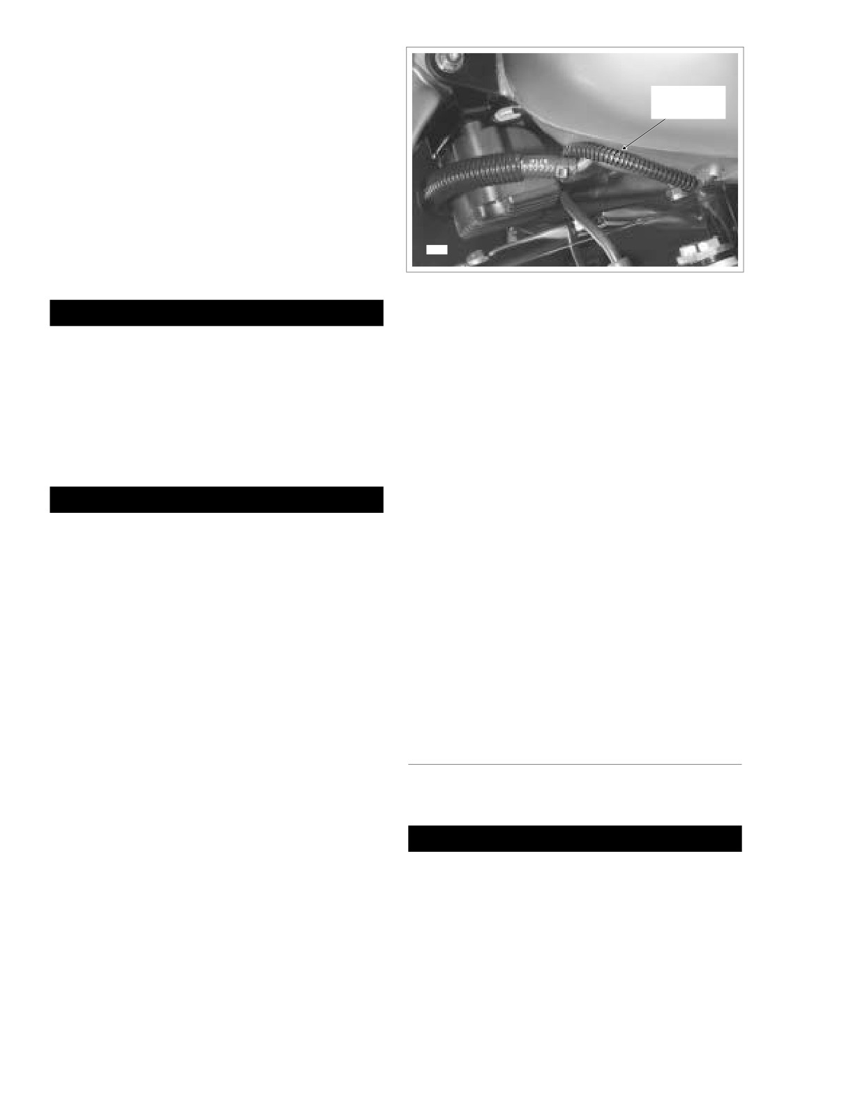
Figure 9-13. Fuel Gauge (FLHR/C/S)
1WARNING
11.
Install acorn nut at top of instrument console and tighten
Exercise caution to avoid twisting the fuel supply line fit-
to 50-90 in-lbs (5.7-10.2 Nm). If present, also install
ting, as any cracks in the plastic construction of the line
Phillips screw and large flat washer (absent on FLHRSI
can result in gas leaks. Gas leakage can cause fire or
models). Tighten screw to 36-60 in-lbs (4.1-6.8 Nm).
explosion which could result in death or serious injury.
12.
Connect fuel gauge to main harness. Route pin housing
3. Locate quick-connect fitting on left side of fuel tank. Pull
and convoluted tubing forward and then inboard
up on chrome sleeve and insert neck of fuel supply line
between front of crossover hose fitting and bottom of fuel
fitting. While pushing up on bottom of fitting, pull down
tank. Mate pin and socket halves of fuel gauge connec-
on chrome sleeve until it “clicks” into the locked position.
tor [117], 4-place Multilock. Feed connector into tunnel
of fuel tank. See Figure 9-13.
13.
Snap anchor of new cable strap into hole on left side of
1WARNING
frame backbone. Tighten cable strap capturing main har-
To avoid an uncontrolled discharge or spray of gasoline,
ness bundle, instrument console conduit, and fuel vapor
always be sure the quick-connect fitting is properly
vent tube. Cut any excess cable strap material. See Fig-
mated. A slight tug on the fuel supply line fitting will ver-
ure 9-12.
ify this condition. Gasoline is extremely flammable and
14.
Insert bolt through battery negative cable (black) into
highly explosive. Inadequate safety precautions could
threaded hole of battery negative (-) terminal. Tighten
result in death or serious injury.
bolt to 60-96 in-lbs (6.8-10.9 Nm).
4. Connect fuel vapor vent tube to fitting at top of canopy.
15.
Install the 15 amp fuel pump fuse. See Figure 9-10. If
necessary, see Section 9.2 ELECTRICAL BRACKET
5. Slide head of console mounting bolt into slot at top of
ASSEMBLY, EFI FUSES, INSTALLATION.
canopy.
16.
Install seat. See Section 2.24 SEAT, INSTALLATION.
6. Moving instrument console toward installed position,
install fuel level sender/fuel pump connector [141], 3-
place Mini-Deutsch, at top of canopy. Bend flexible
clamp to capture main harness conduit.
PARTIAL REMOVAL
7. Align hole in instrument console with console mounting
bolt and place into position on fuel tank.
FLHT/C/U/I, FLTRI
8. Start fuel tank front mounting bolts (with flat washers)
into left and right side of frame.
1WARNING
9. Install bolt (with flat washer) to secure rear of fuel tank to
frame backbone. On FLHRSI models, capture instru-
Gasoline is extremely flammable and highly explosive.
ment console bracket during installation. Tighten bolt to
When servicing the fuel system, do not smoke or allow
15-20 ft-lbs (20-27 Nm).
open flame or sparks in the vicinity. Inadequate safety
precautions could result in death or serious injury.
10. Tighten fuel tank front mounting bolts to 15-20 ft-lbs (20-
27 Nm).
1.
Remove seat. See Section 2.24 SEAT, REMOVAL.
9-12
2005 Touring: Fuel Injection
HOME
1WARNING
1WARNING
The gasoline in the fuel supply line downstream of the
Exercise caution to avoid twisting the fuel supply line fit-
fuel pump is under high pressure (58 psi). To avoid an
ting, as any cracks in the plastic construction of the line
uncontrolled discharge or spray of gasoline, always
can result in gas leaks. Gas leakage can cause fire or
purge the system of high pressure gas before the fuel
explosion which could result in death or serious injury.
supply line is disconnected. Inadequate safety precau-
11. Locate quick-connect fitting on left side of fuel tank. Pull
tions could result in death or serious injury.
up on chrome sleeve and pull down on fuel supply line
2.
Purge the fuel supply line of high pressure gas. Proceed
fitting to disconnect. See Figure 9-11.
as follows:
12. Remove two fuel tank front mounting bolts (with flat
a. Remove the 15 amp fuel pump fuse. See Figure 9-
washers) from left and right side of frame. Remove bolt
10. If necessary, see Section
9.2 ELECTRICAL
(with flat washer) to free rear of fuel tank from frame
BRACKET ASSEMBLY, EFI FUSES, REMOVAL.
backbone.
b. Start the engine and allow the vehicle to run.
NOTE
c. When the engine stalls, operate starter for 3 sec-
The fuel tank mounting bolts have both an internal TORX
onds to remove remaining fuel from fuel lines.
recess and an external hex, which allows them to be
removed with either a T40 TORX bit or a 1/2 inch open end/
box wrench. Use of the external hex allows the front mount-
1WARNING
ing bolts to be removed without having to loosen or remove
the fairing lowers, if installed.
To protect against shock and accidental start-up of vehi-
cle, disconnect the negative battery cable before pro-
13. Raise the fuel tank approximately 2 inches. Move the
ceeding. Inadequate safety precautions could result in
fuel tank crossover hose to the rear of the ignition coil,
death or serious injury.
so that the tank can be raised an additional 2-3 inches.
Move fuel tank straight back and rest on frame back-
3.
Unthread bolt and remove battery negative cable (black)
bone.
from battery negative (-) terminal.
14. Obtain several 1 x 2 inch wooden blocks. Raise front and
4.
Carefully cut anchored cable strap securing main har-
rear of fuel tank off the frame backbone by placing
ness bundles, console pod conduit (Ultra models only),
blocks in tunnel at bottom of tank.
fuel level sender/fuel pump conduit, and fuel vapor vent
tube to left side of frame backbone.
5.
Open fuel door on console. Remove two Allen head
FLHR/C/S/I
screws inboard of rubber bumpers. These screws secure
1.
See Section 9.4 FUEL TANK (FUEL INJECTED), PAR-
console to clip nuts on the canopy bracket.
TIAL REMOVAL, FLHT/C/U/I, FLTRI, steps 1-3.
6.
Remove Allen head screw to detach flange at rear of
2.
Remove two fuel tank front mounting bolts (with flat
console from clip nut on fuel tank weldment.
washers) from left and right side of frame. Remove bolt
7.
Lay a clean shop towel on forward part of rear fender.
(with flat washer) to free rear of fuel tank from frame
backbone. On FLHRSI models, removal of rear bolt also
8.
Remove filler cap from neck of fuel tank. Remove con-
sole and lay upside down on shop towel. Reinstall filler
releases instrument console bracket.
cap.
3.
Carefully cut anchored cable strap securing main har-
ness bundle, instrument console conduit, and fuel vapor
9.
Depress button on socket side and remove fuel level
vent tube to left side of frame backbone.
sender/fuel pump connector [141], 3-place Mini-Deut-
sch, at top of canopy.
4.
Remove acorn nut from instrument console. If present,
also remove Phillips screw and large flat washer (absent
10. Gently pry fuel vapor vent tube from fitting on filler neck
on FLHRSI models).
of fuel tank. Exercise caution to avoid pulling fitting from
filler neck.
5.
Raise instrument console and bend back flexible clamp
on canopy to release main harness conduit. Depress
button on socket side and remove fuel level sender/fuel
1WARNING
pump connector [141], 3-place Mini-Deutsch.
A small amount of gasoline may drain from the fuel sup-
ply line when disconnected from the fuel tank. Thor-
CAUTION
oughly wipe up any spilled fuel immediately. Dispose of
rags in a suitable manner. Gasoline is extremely flamma-
When removing instrument console, exercise caution to
ble and highly explosive. Inadequate safety precautions
avoid damaging speedometer unit. Wrap console in a
could result in death or serious injury.
clean, dry shop towel to prevent damage.
2005 Touring: Fuel Injection
9-13