Harley Davidson 2005 touring models. Service repair manual - page 29
HOME
Left Handlebar
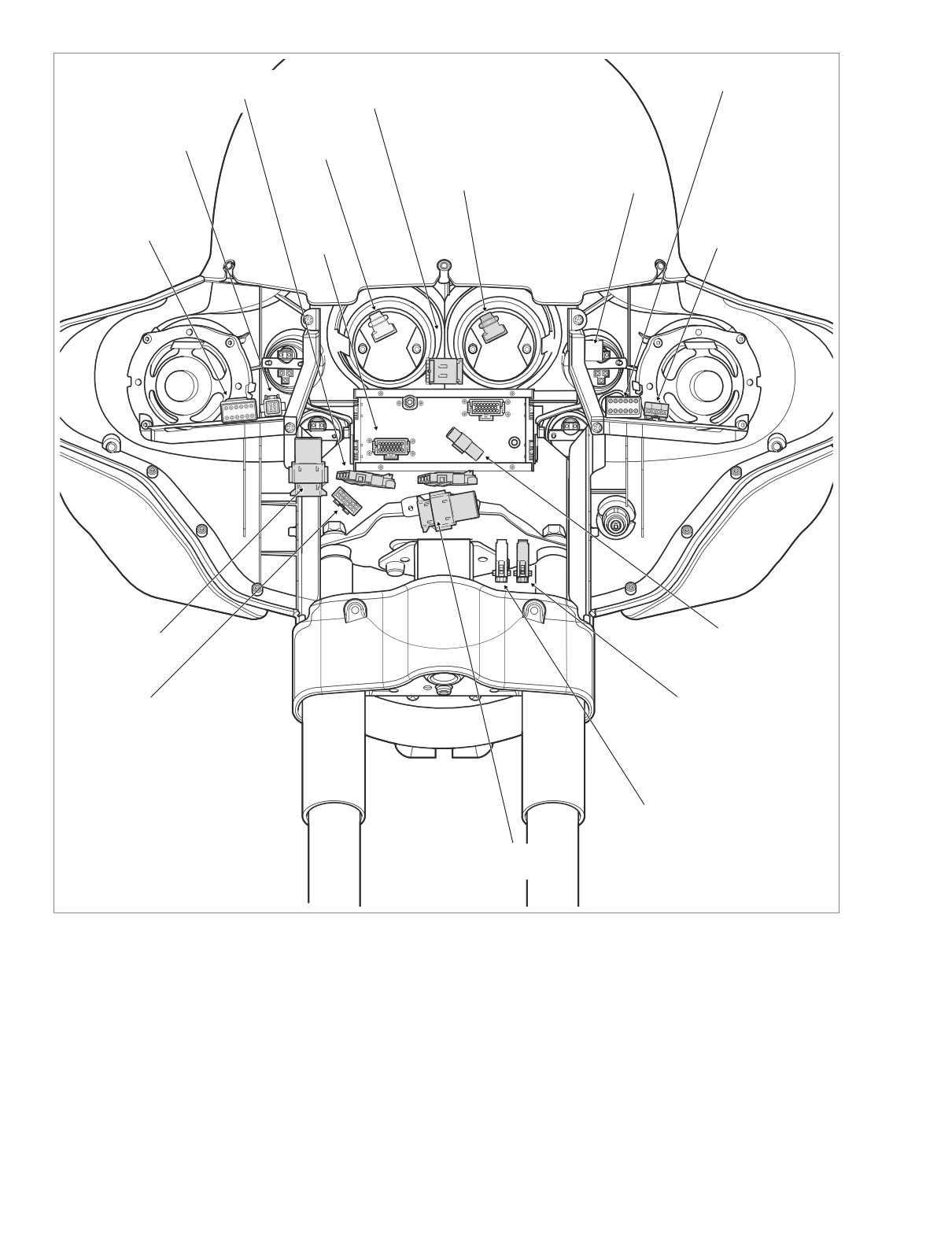
Main to Interconnect
Switch Controls [24]
Harness [15]
Indicator
Lamps [21]
Main to Interconnect
Harness [156]
Tachometer
Gauge [108]
Ambient
Speedometer
Temperature
Gauge [39]
Sensor [107]
Main to Interconnect
Harness [2]
Front Turn
Signals [31]
Radio [27]
Main to Interconnect
Audio to Interconnect
Harness [1]
Harness [6]
Front
Fairing Cap
Fender Tip [32]
Switches [105]
Auxiliary
Lamp [73]
Right Handlebar
Switch Controls [22]
f2238x8x
Figure 8-159. Inner Fairing - Interconnect Harness Connectors (FLHTC/U)
8.
See Figure 8-160. Remove connectors from
spade con-
9. Feed
conduit (with orange tape) terminating in left side
tacts as follows:
speaker, fuel gauge, cigarette lighter and front turn sig-
nal connectors to mid section of inner fairing
(area
Left side:
between left and right fairing brackets). Also feed conduit
● Left speaker
terminating in left handlebar switch controls connector
● Fuel gauge and lamp
[24] to mid section.
● Cigarette lighter
8-130
2005 Touring: Electrical
HOME
f2238x8x
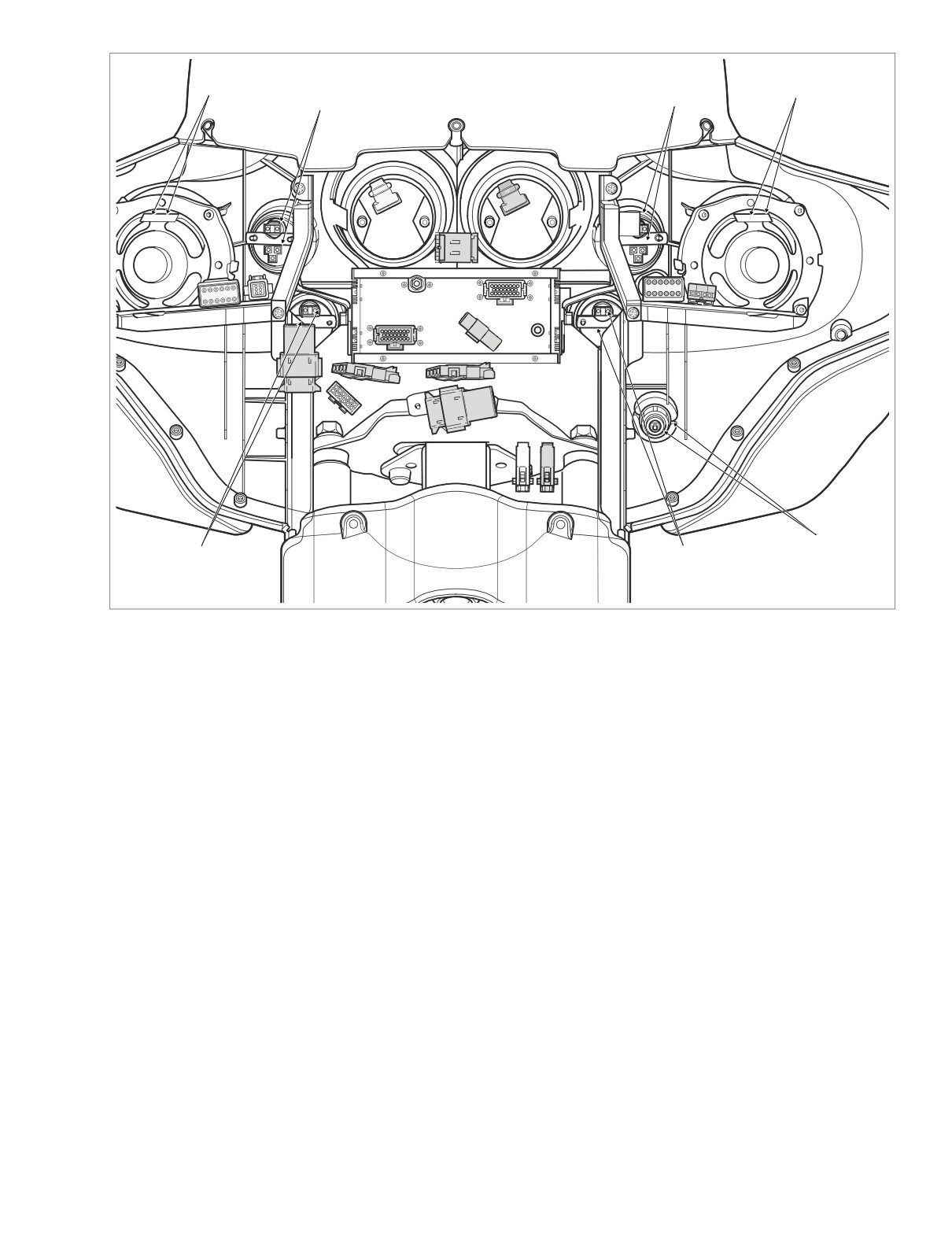
Right
Left
Speaker
Voltmeter Gauge
Fuel Gauge
Speaker
and Lamp
and Lamp
Cigarette
Oil Pressure
Ambient
Lighter
Gauge and Lamp
Temperature
Gauge and Lamp
Figure 8-160. Inner Fairing - Interconnect Harness Connectors (FLHTC/U)
10. Pull harness ground socket terminal from spade contact
INSTALLATION
fastened to top of upper fork bracket (left side).
NOTE
11. See Figure 8-160. Remove connectors from spade con-
When referencing inner fairing locations, the term “fairing
tacts as follows:
bracket” refers to either the left or right vertical support, while
Right side:
the term “support brace” refers to either the left or right hori-
● Right speaker
zontal support. References to left and right always refers to
left and right side of motorcycle.
● Voltmeter gauge and lamp
1.
Center interconnect harness on top of radio. To verify
12. Feed conduit (with orange tape) terminating in right side
proper orientation, be sure that convoluted tubing (with
speaker and voltmeter gauge connectors to mid section
anchor) of headlamp connector is on left side of motor-
of inner fairing (area between left and right fairing brack-
cycle, while conduit (with anchor) of fairing cap switch
ets). Also feed conduit terminating in main to intercon-
connector is on the right.
nect harness connectors [2] and [156] to mid section.
2.
Install anchors on convoluted tubing of interconnect har-
13. If present, remove connectors from spade contacts as
ness into lower outboard ears of speedometer and
follows:
tachometer brackets. See Figure 8-158.
● Oil pressure gauge and lamp
3.
If present, install connectors onto spade contacts as fol-
lows:
● Ambient temperature gauge and lamp
● Oil pressure gauge and lamp
14. Remove interconnect harness from motorcycle.
● Ambient temperature gauge and lamp
2005 Touring: Electrical
8-131
HOME
4.
From mid section of inner fairing (area between left and
right fairing brackets), feed conduit (with orange tape)
9421
terminating in left side speaker, fuel gauge, cigarette
lighter and front turn signal connectors behind left fairing
bracket to area of left support brace.
5.
Install connectors onto spade contacts as follows:
Left side:
● Left speaker
● Fuel gauge and lamp
● Cigarette lighter; connect the orange/white wire
socket terminal to the socket spade contact, the
black wire socket terminal to the shell contact.
Anchor
6.
From mid section of inner fairing (area between left and
right fairing brackets), also feed conduit terminating in
left handlebar switch controls connector [24] behind left
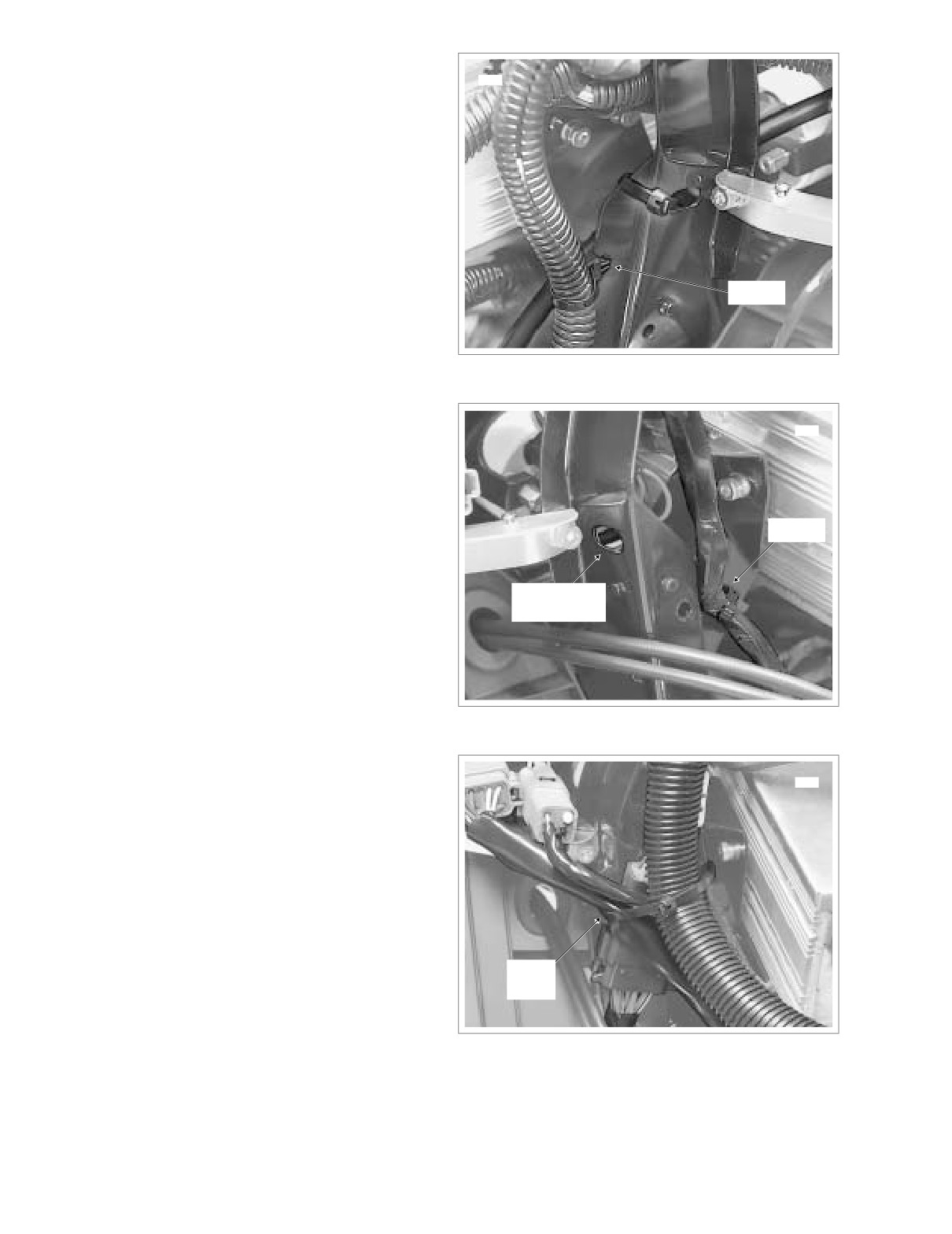
Figure 8-161. Anchor Convoluted Tubing of
fairing bracket to area of left support brace.
Headlamp Connector
7.
Push harness ground socket terminal onto spade con-
tact fastened to top of upper fork bracket (left side).
9423
8.
From mid section of inner fairing, feed conduit (with
orange tape) terminating in right side speaker and volt-
meter gauge connectors behind right fairing bracket to
area of right support brace.
Anchor
9.
Install connectors onto spade contacts as follows:
Right side:
● Right speaker
Oval Shaped
Hole
● Voltmeter gauge and lamp
10.
From mid section of inner fairing, also feed conduit ter-
minating in main to interconnect harness connectors [2]
and [156] behind right fairing bracket to area of right sup-
port brace.
Figure 8-162. Anchor Conduit of Fairing Cap
11.
Mate pin and socket halves of the following connectors
Switch Connector
and fix positions using retaining devices, if present:
a. Main to interconnect harness connector
[2],
12-
9422
place Deutsch (gray); T-stud on right fairing support
brace (outboard side).
b. Main to interconnect harness connector [156], 6-
place Deutsch (gray); T-stud on right fairing support
brace (inboard side).
c. Radio connector [27], 23-place Amp (black); back of
radio (right side).
d. Indicator lamps
[21];
10-place Multilock
(black);
above radio (between speedometer and tachometer
Cable
gauges).
Strap
e. Speedometer connector
[39];
12-place Packard
(black); back of speedometer. Slide odometer reset
switch through hole in inner fairing and install rubber
Figure 8-163. Cable Strap Convoluted Tubing, Conduit
boot.
and Connector to Fairing Bracket
8-132
2005 Touring: Electrical
HOME
f.
Tachometer connector
[108];
12-place Packard
13.
On opposite side of inner fairing, install anchor on con-
(gray); back of tachometer.
duit of fairing cap switch connector into hole in lower
wing of right side radio support bracket. See Figure 8-
g.
Ambient temperature sensor connector
[107], if
162.
present; 3-place Multilock (black); anchor in hole on
outboard side of left fairing bracket.
14.
Using oval shaped hole in right fairing bracket, install
new cable strap capturing convoluted tubing of intercon-
h.
Left handlebar switch controls connector [24], 12-
nect harness, conduit of main to interconnect harness
place Deutsch (gray); T-stud on top of left fairing
connectors [15] and [156], and housing of main to inter-
support brace (inboard side).
connect harness connector [1]. See Figure 8-162 and
i.
Front turn signal connector [31], 6-place Multilock
Figure 8-163.
(black); T-stud on top of left fairing support brace
15.
Install the windshield and outer fairing. See Section 2.29
(outboard side).
UPPER FAIRING/WINDSHIELD (FLHT/C/U), OUTER
j.
Main to interconnect harness connector [1],
12-
FAIRING/WINDSHIELD, INSTALLATION.
place Deutsch (black); T-stud at front of right fairing
16.
Install maxi-fuse. See Section
8.3 SYSTEM FUSES,
bracket.
MAXI-FUSE, INSTALLATION.
k.
Main to interconnect harness connector [15],
4-
place Packard (black); anchor in hole at bottom of
radio (right side).
l.
Fairing cap switch connector [105], 12-place Mul-
tilock (black); top of upper fork bracket (right side).
m.
Right handlebar switch controls connector [22], 12-
place Deutsch (black); T-stud on fork stem nut lock
plate (left side).
n.
Audio to interconnect harness connector
[6], if
present; 3-place Deutsch (black); back of radio.
o.
Auxiliary lamps connector
[73],
2-place Multilock
(white); below upper fork bracket (left side).
p.
Front fender tip lamp connector [32], 2-place Mul-
tilock (black); below upper fork bracket (left side).
12.
Install anchor on convoluted tubing of headlamp connec-
tor into hole in left fairing bracket. See Figure 8-161.
2005 Touring: Electrical
8-133
HOME
5. See Figure 8-164. Disconnect main harness from inter-
INTERCONNECT HARNESS (FLTR)
connect harness as follows:
● Main to interconnect harness connector [1], 12-
REMOVAL
place Deutsch (black); below radio (right side).
1.
Remove maxi-fuse. See Section 8.3 SYSTEM FUSES,
● Main to interconnect harness connector [2], 12-
MAXI-FUSE, REMOVAL.
place Deutsch (gray); below radio (right side).
2. Place protective material on top of front fender to protect
● Main to interconnect harness connector [15], 4-
paint from scratches or other damage.
place Packard (black); below radio (right side).
3.
Remove the outer fairing and windshield. See Section
● Main to interconnect harness connector [156], 6-
2.30 UPPER FAIRING/WINDSHIELD (FLTR), OUTER
place Deutsch (gray); below radio (right side).
FAIRING, REMOVAL.
4.
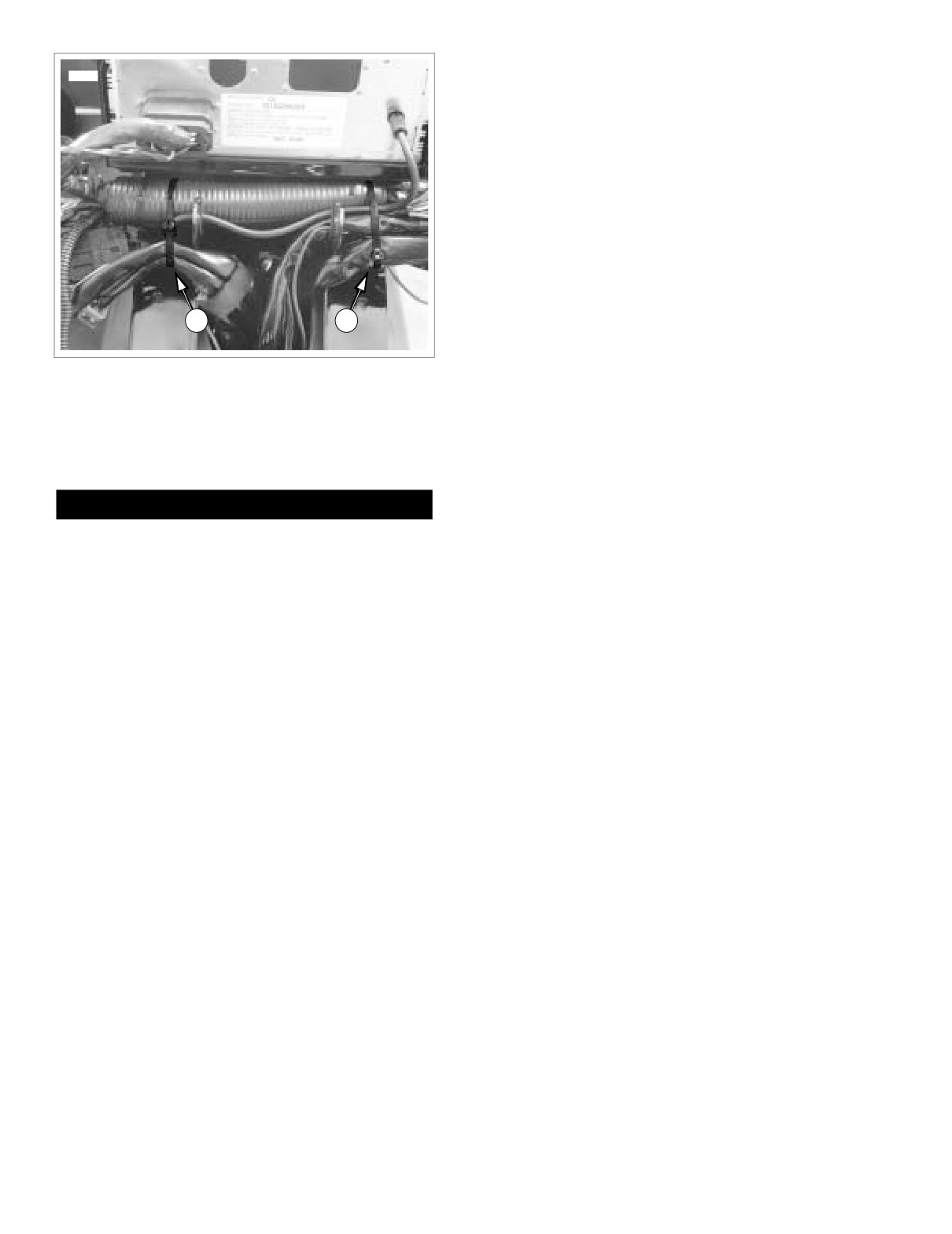
Carefully cut two cable straps to free wire bundles and
6. See Figure 8-164. Disconnect handlebar switch controls
conduit from convoluted tubing of interconnect harness
from interconnect harness. Disconnect radio and radio
and allow to hang naturally. See Figure 8-166.
ground. Proceed as follows:
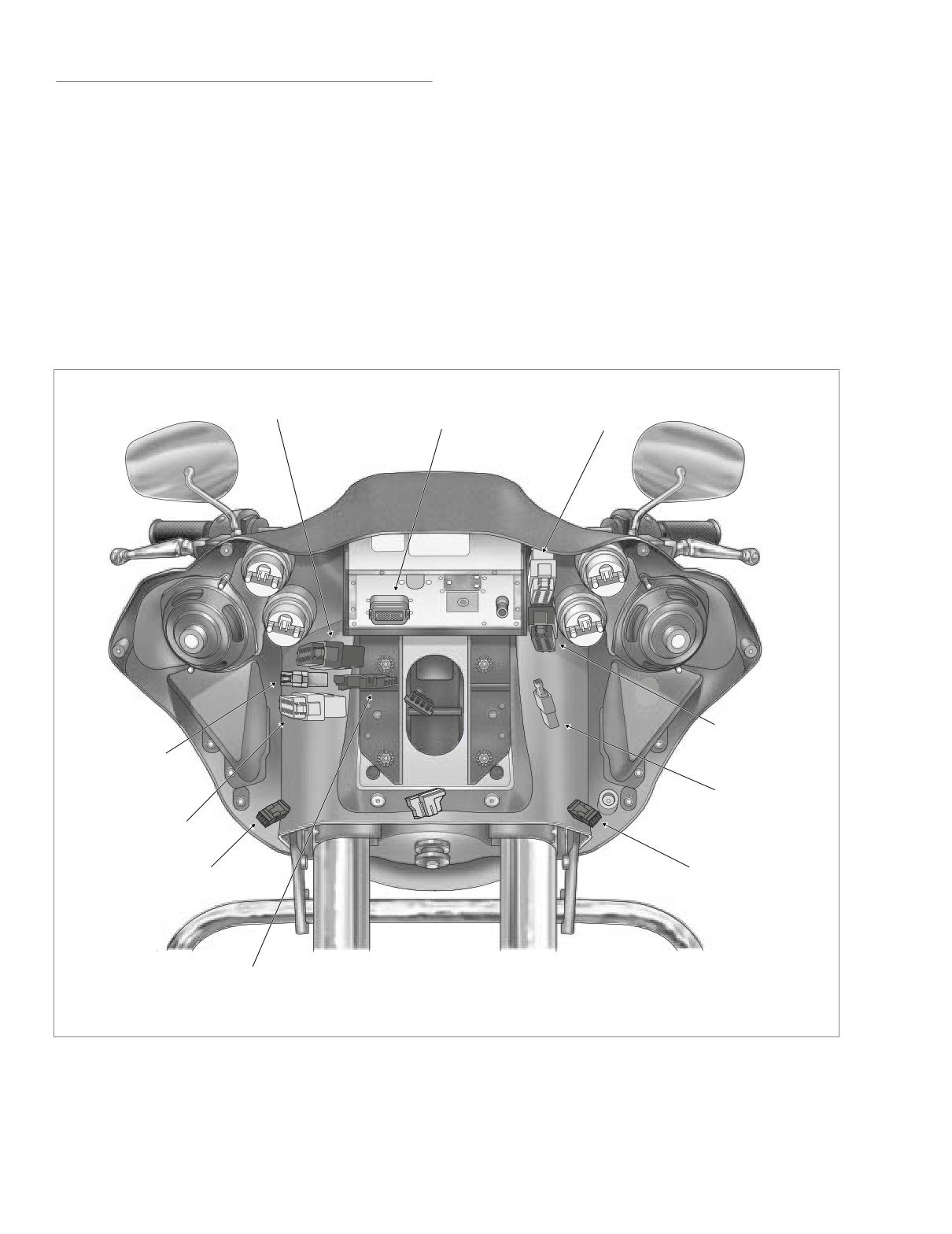
Main to Interconnect
Harness [1]
Left Handlebar
Radio [27]
Switch Controls [24]
Right Handlebar
Switch Controls [22]
Main to Interconnect
Harness [156]
Radio
Ground
Main to Interconnect
Harness [2]
Right Turn
Left Turn
Signal [31R]
Signal [31L]
Main to Interconnect
Harness [15]
f2269x8x
Figure 8-164. Inner Fairing Connections (FLTR)
8-134
2005 Touring: Electrical
HOME
Instrument Nacelle
Indicator
f2219x8x
Switches [105]
Lamps [21]
Tachometer
Gauge [108]
Speedometer
Gauge [39]
Speaker
Ambient
Switch [105]
Temperature
Sensor [107]
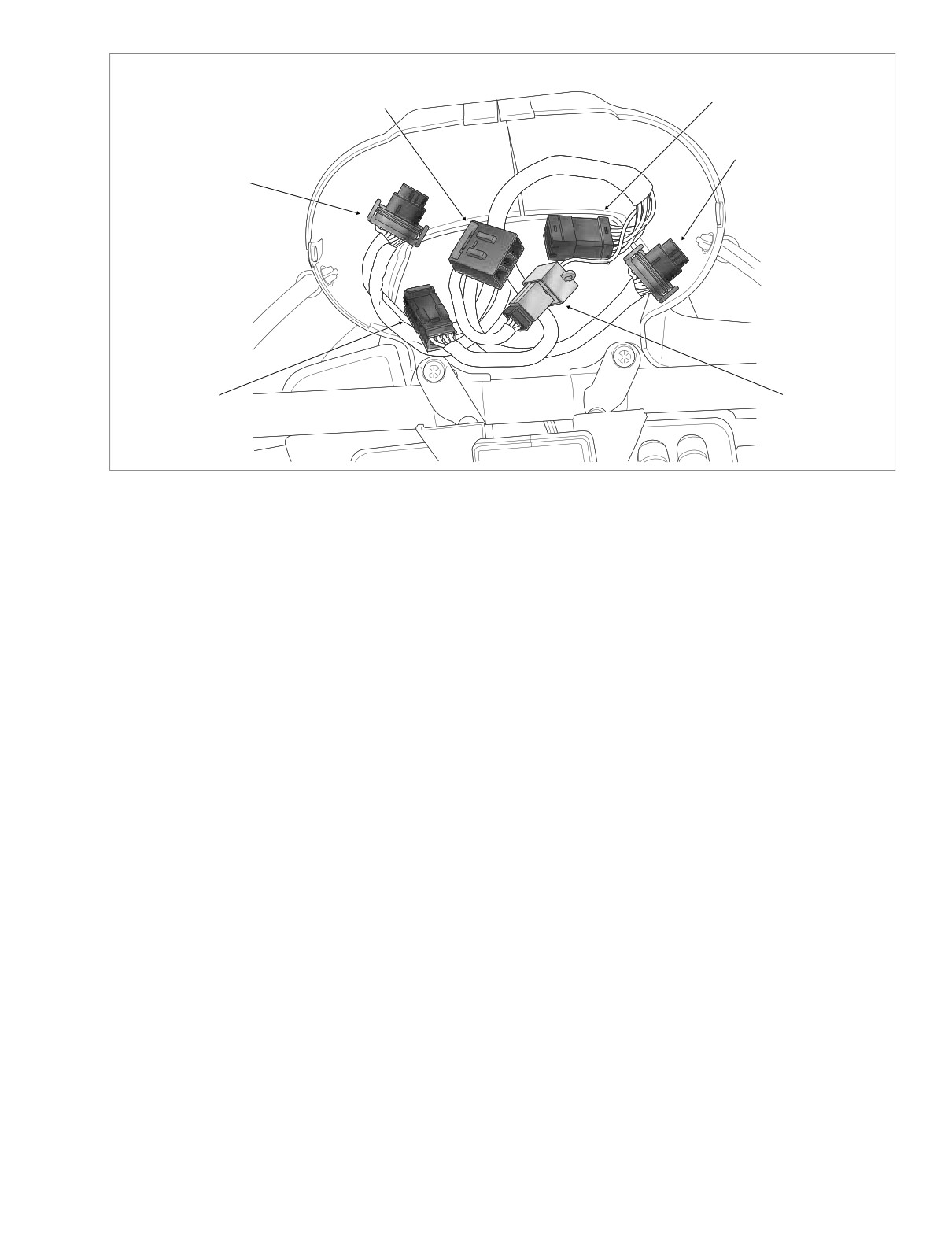
Figure 8-165. Instrument Nacelle (Bezel Removed)
● Left handlebar switch controls connector [24], 12-
9.
See Figure 8-165. Draw branches of interconnect har-
place Deutsch (gray); T-stud on left side of radio
ness (terminating in odometer reset switch and speed-
bracket.
ometer, tachometer, indicator lamps, instrument nacelle
switch and ambient temperature sensor connectors)
● Right handlebar switch controls connector [22], 12-
from instrument nacelle through tunnel of fairing bracket
place Deutsch (black); T-stud on left side of radio
to front of inner fairing. Allow the interconnect harness to
bracket.
hang along the left side of the front fender.
NOTE
10.
Remove connectors from spade contacts as follows:
Push on each handlebar connector to disengage small end
Left side:
of slot on attachment clip from T-stud on radio bracket. Lift
connector off T-stud.
● Left speaker
● Fuel gauge and lamp (with orange tape)
● Radio connector [27], 23-place Amp (black); back of
radio (right side).
● Ambient temperature gauge and lamp
● Radio ground; single spade and socket terminal;
● Cigarette lighter
below radio (left side).
Right side:
7. Remove left side of instrument nacelle. See Section 2.30
● Right speaker
UPPER FAIRING/WINDSHIELD (FLTR), INSTRUMENT
NACELLE, REMOVAL, steps 1-6.
● Voltmeter gauge and lamp (with orange tape)
● Oil pressure gauge and lamp
8. See Figure
8-165. Disconnect instrument nacelle
switches and ambient temperature sensor from intercon-
nect harness as follows:
11.
Free conduit of front turn signal lamp connectors [31L]
and [31R], 3-place Multilocks, from flexible clips on sides
● Instrument nacelle switch connector [105], 12-place
of inner fairing.
Multilock.
12.
Remove interconnect harness from motorcycle. Remove
● Ambient temperature sensor connector [107], 3-
radio antenna cable connector [51] at back of radio (left
place Multilock.
side) to facilitate removal.
2005 Touring: Electrical
8-135
HOME
3.
Find branch of interconnect harness terminating in
9427a
odometer reset switch and speedometer, tachometer,
indicator lamps, instrument nacelle switch and ambient
temperature sensor connectors. Feed connectors and
conduit from front of inner fairing through tunnel of fair-
ing bracket and then out through opening at top of fairing
bracket to instrument nacelle.
4.
See Figure 8-165. Connect instrument nacelle switches
and ambient temperature sensor to interconnect har-
ness as follows:
● Instrument nacelle switch connector [105], 12-place
Multilock.
● Ambient temperature sensor connector [107], 3-
1
2
place Multilock.
5.
See Figure 8-164. Connect handlebar switch controls to
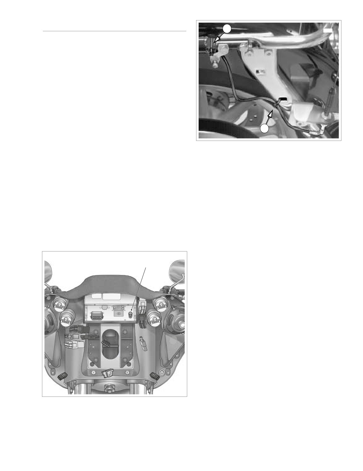
Figure 8-166. Cable Strap Convoluted Tubing
interconnect harness. Connect radio and radio ground.
and Conduit
Proceed as follows:
● Left handlebar switch controls connector [24], 12-
place Deutsch (gray); T-stud on left side of radio
INSTALLATION
bracket.
● Right handlebar switch controls connector [22], 12-
place Deutsch (black); T-stud on left side of radio
CAUTION
bracket.
To avoid chafing wires of interconnect harness, verify
NOTE
that trim strips are installed on hooks of radio bracket.
Place large end of slot on attachment clip over T-stud on
1.
Center convoluted tubing of interconnect harness above
radio bracket and push on each handlebar connector to
and inboard of hooks on radio bracket. See Figure 8-
engage small end of slot.
166. To verify proper orientation, be sure that long length
of conduit terminating in socket terminals of cigarette
● Radio connector [27], 23-place Amp (black); back of
lighter is on left side of motorcycle. Install radio antenna
radio (right side).
cable connector
[51] at back of radio
(left side), if
removed.
● Radio ground; single spade and socket terminal;
below radio (left side).
2.
Install connectors onto spade contacts as follows:
6. See Figure 8-164. Connect main harness to intercon-
Left side:
nect harness as follows:
● Left speaker
● Main to interconnect harness connector [1], 12-
place Deutsch (black); below radio (right side).
● Fuel gauge and lamp (with orange tape)
● Main to interconnect harness connector [2], 12-
● Ambient temperature gauge and lamp
place Deutsch (gray); below radio (right side).
● Cigarette lighter; connect the orange/white wire
● Main to interconnect harness connector [15], 4-
socket terminal to the socket spade contact, the
place Packard (black); below radio (right side).
black wire socket terminal to the shell contact.
● Main to interconnect harness connector [156], 6-
place Deutsch (gray); below radio (right side).
Right side:
7.
Orient connectors as shown in Figure 8-164. Install two
● Right speaker
new cable straps outboard of radio bracket hooks to
● Voltmeter gauge and lamp (with orange tape)
secure wire bundles and conduit to convoluted tubing of
interconnect harness. Cut any excess cable strap mate-
● Oil pressure gauge and lamp
rial. See Figure 8-166.
8-136
2005 Touring: Electrical
HOME
8. Capture conduit of front turn signal lamp connectors
11. Install bezel. See BEZEL, INSTALLATION, in this sec-
[31L] and [31R], 3-place Multilocks, in flexible clips on
tion.
sides of inner fairing.
12. Install maxi-fuse. See Section
8.3 SYSTEM FUSES,
9. Install the outer fairing and windshield. See Section 2.30
MAXI-FUSE, INSTALLATION.
UPPER FAIRING/WINDSHIELD (FLTR), OUTER FAIR-
ING, INSTALLATION.
10. Install left side of instrument nacelle. See Section 2.30
UPPER FAIRING/WINDSHIELD (FLTR), INSTRUMENT
NACELLE, INSTALLATION, steps 3-7 and 9-10.
2005 Touring: Electrical
8-137
HOME
RADIO ANTENNA CABLE
(FLHTC/U)
Cable
Clip
Grommet
REMOVAL
1.
Remove fuel tank. For carbureted models, see Section
4.7 FUEL TANK
(CARBURETED), COMPLETE
REMOVAL, FLHT/C. For fuel injected models, see Sec-
tion 9.4 FUEL TANK (FUEL INJECTED), COMPLETE
REMOVAL, FLHT/C/U/I, FLTRI.
Cavity
2.
Remove left side saddlebag. See Section 2.25 SAD-
DLEBAG, REMOVAL.
Tour-Pak Lights
3.
Gently pull side cover from frame downtubes (no tools
Connector [12]
required).
4.
Remove the outer fairing and windshield. See Section
Radio Antenna
2.29 UPPER FAIRING/WINDSHIELD
(FLHT/C/U),
Cable
OUTER FAIRING/WINDSHIELD, REMOVAL.
f1466a2x
5.
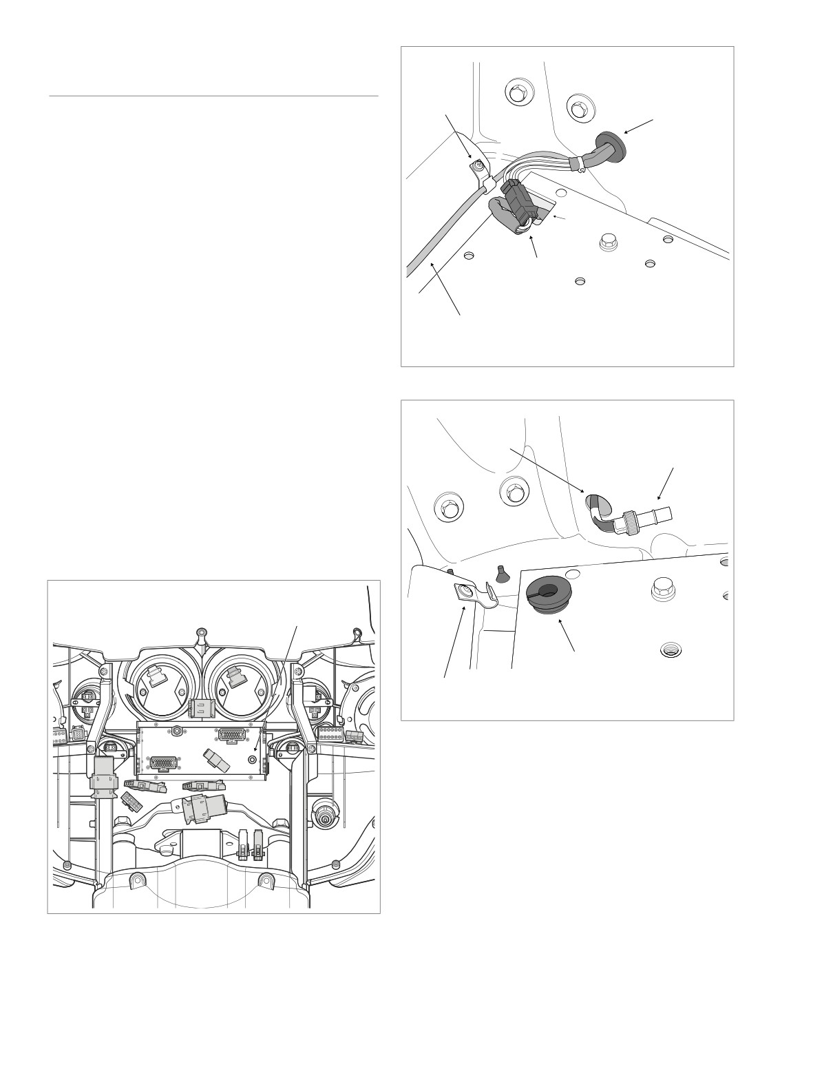
Remove radio antenna cable connector [51] at back of
radio (left side). See Figure 8-167. Carefully cut cable
Figure 8-168. Disconnect Tour-Pak Lights Connector
where it exits branch of main harness conduit.
6.
Remove screw, ground wire ring terminal and P-clamp to
release main harness (and audio harness on FLHTCU)
Tour-Pak
Hole
Radio Antenna
from right side of steering head.
Cable Connector
7.
Carefully cut cable straps securing main harness to
frame backbone, left frame tube and luggage rack rail.
See Figure 8-170.
8.
Open Tour-Pak and proceed as follows:
FLHTC: Remove rubber mat.
Radio Antenna
Cable [51]
Grommet
Cable
Clip
f1465a2x
Figure 8-169. Feed Main Harness Thru Tour-Pak Hole
FLHTCU:
Open map pocket and remove acorn nuts
(with flat washers). Remove map pocket and molded
liner from Tour-Pak.
9. Depress external latch and remove bulb socket from left
side of Tour-Pak.
10. Rotate knurled ring in a counterclockwise direction to
separate pin and socket halves of radio antenna cable
f2238x8x
connector. Release cable from two clips at bottom of
Tour-Pak.
Figure 8-167. Remove Outer Fairing (FLHTC/U)
8-138
2005 Touring: Electrical
HOME
11. Depress button and separate pin and socket halves of
Tour-Pak lights connector [12], 3-place Multilock, inside
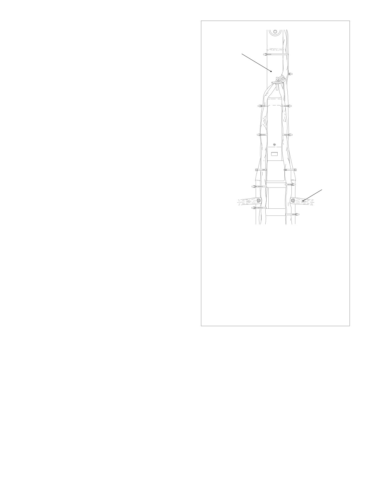
A = Anchored
Tour-Pak. See Figure 8-168.
Frame
12. Pull grommet into Tour-Pak and remove from main har-
Backbone
ness conduit.
1
13. Pull Tour-Pak lights and radio antenna cable connectors
through hole at front of Tour-Pak. See Figure 8-169.
2 A
14. Carefully cut radio antenna cable where it exits main
harness conduit.
3 A
INSTALLATION
1. Place new radio antenna cable on motorcycle following
original routing. Note that the cable follows the branches
4 A
of the main harness (and audio harness on FLHTCU)
routed to the rear left side of the motorcycle.
NOTE
Specifically, from the front of the inner fairing, the radio
5 A
antenna cable is routed under the fairing cap where it passes
through a P-clamp on the right side of the steering head. The
Saddlebag
6
Guard
cable then runs along the right side of the frame backbone,
where it crosses to the left side at the main harness anchor in
the center of the frame backbone. From this point, the cable
follows the left side of the frame backbone, runs along the
7
inboard side of the upper frame tube and then continues
down the luggage rack rail where it passes through the hole
f2225x8x
at the front of the Tour-Pak.
1
Captures main harness, cruise roll-off switch conduit,
2.
Feed Tour-Pak lights and radio antenna cable connec-
audio harness (FLHTCUI only) and frame backbone.
tors and conduit through hole at front of Tour-Pak. Cap-
2
Captures main harness and audio harness
(FLHTCUI
ture conduit in grommet. Install grommet in hole with the
only). ANCHORED.
larger OD facing inside.
3
4
Captures main harness and audio harness
(FLHTCUI
only). ANCHORED.
3.
Mate pin and socket halves of Tour-Pak lights connector
5
Captures main harness, audio harness (FLHTCUI only),
[12], 3-place Multilock, and tuck into cavity inside Tour-
fuel vapor vent tube and console pod or instrument
Pak. See Figure 8-168.
console conduit. ANCHORED.
6
Captures main harness, audio harness (FLHTCUI only),
4.
Rotate knurled ring in a clockwise direction to mate pin
console pod or instrument console conduit and upper
frame tube.
and socket halves of radio antenna cable connector.
Capture cable in two clips at bottom of Tour-Pak.
7
Captures main harness, audio harness (FLHTCUI only),
console pod conduit (FLHTCUI only) and upper frame
tube.
5.
Install bulb socket on left side of Tour-Pak.
6.
Proceed as follows:
Figure 8-170. Install Cable Straps
FLHTC: Install rubber mat in Tour-Pak. Close Tour-Pak.
FLHTCU: Install molded liner in Tour-Pak. Install map
pocket and secure using acorn nuts (with flat washers).
9.
At front of top engine stabilizer bracket, install new 14
Close Tour-Pak.
inch cable strap capturing frame backbone, radio
antenna cable, main harness and audio harness (if
7.
At front of inner fairing, connect radio antenna cable
present). Tighten cable strap, but leave loose enough so
connector [51] to back of radio. See Figure 8-167.
that one finger can be inserted between strap and frame
backbone. Do not overtighten. Cut any excess cable
8.
On right side of motorcycle, capture radio antenna cable,
strap material.
main harness and audio harness (if present) in P-clamp.
Install ground wire ring terminal on screw and fasten P-
10.
Install remaining cables straps as shown in Figure 8-
clamp to right side of steering head.
170.
2005 Touring: Electrical
8-139
HOME
11. Install the outer fairing and windshield. See Section 2.30
13. Install left side saddlebag. See Section 2.25 SADDLE-
UPPER FAIRING/WINDSHIELD (FLTR), OUTER FAIR-
BAG, INSTALLATION.
ING, INSTALLATION.
14. Install fuel tank. For carbureted models, see Section 4.7
FUEL TANK (CARBURETED), INSTALLATION (AFTER
12. Align barbed studs in left side cover with grommets in
COMPLETE REMOVAL), FLHT/C. For fuel injected
frame downtubes and push firmly into place (no tools
models, see Section
9.4 FUEL TANK
(FUEL
required).
INJECTED), INSTALLATION
(AFTER COMPLETE
REMOVAL), FLHT/C/U/I, FLTRI.
8-140
2005 Touring: Electrical
HOME
RADIO ANTENNA CABLE (FLTR)
1
9425
REMOVAL
1.
Remove fuel tank. See Section 9.4 FUEL TANK (FUEL
INJECTED), COMPLETE REMOVAL, FLHT/C/U/I,
FLTRI.
2.
Remove left side saddlebag. See Section 2.25 SAD-
DLEBAG, REMOVAL.
3.
Gently pull side cover from frame downtubes (no tools
required).
4.
Remove the outer fairing and windshield. See Section
2.30 UPPER FAIRING/WINDSHIELD (FLTR), OUTER
2
FAIRING, REMOVAL.
5.
Remove radio antenna cable connector [51] at back of
Figure 8-172. Capture Radio Antenna Cable
radio (left side). See Figure 8-171. Carefully cut cable
where it exits branch of main harness conduit.
9.
Carefully cut cable strap to release radio antenna cable
6.
Remove screw, ground wire ring terminal and P-clamp to
release main harness bundle from right side of steering
from shoulder of upper frame tube (just in front of air
valve mounting bracket). Cut cable strap to release radio
head.
antenna cable from slotted hole in rear fender support.
7.
Carefully cut cable straps securing main harness to
See Figure 8-172.
frame backbone and left frame tube. See Figure 8-173.
10.
At bottom of radio antenna bracket, rotate knurled ring to
separate pin and socket halves of radio antenna cable
8.
On left side of motorcycle, remove bolt (with flat washer)
connector [51].
to remove passenger seat strap and saddlebag front
mounting bracket. Remove Phillips screw and chrome
11.
Draw radio antenna cable forward to area of fuse block
frame tube cover.
bracket. Carefully cut cable where it exits branch of main
harness conduit.
Radio Antenna
INSTALLATION
Cable [51]
1.
Place new radio antenna cable on motorcycle following
original routing. Note that the cable follows the branches
of the main harness routed to the rear left side of the
motorcycle.
NOTE
Specifically, from the front of the inner fairing, the radio
antenna cable is routed through an opening on the right side
of the fairing bracket where it then passes through a P-clamp
on the right side of the steering head. The cable runs rear-
ward along the right side of the frame backbone, where it
crosses to the left side at the main harness anchor in the
center of the frame backbone. From this point, the cable fol-
lows the left side of the frame backbone, runs along the
inboard side of the upper frame tube and then down to the
radio antenna bracket.
2.
Feed radio antenna cable and connector rearward fol-
lowing inboard side of upper frame tube. With the 3-
f2230x2x
place Multilock connector (unused) positioned about as
far rearward as the rear shock air valve, install new
Figure 8-171. Remove Outer Fairing
(FLTR)
cable strap to secure radio antenna cable to shoulder of
2005 Touring: Electrical
8-141
HOME
upper frame tube (just in front of air valve mounting
bracket). Using slotted hole, install new cable strap to
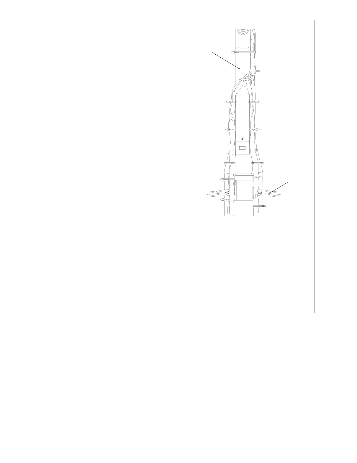
A = Anchored
secure radio antenna cable to rear fender support. See
Figure 8-172.
Frame
Backbone
3.
At bottom of radio antenna bracket, rotate knurled ring to
1
mate pin and socket halves of radio antenna cable con-
nector [51].
4.
Install chrome frame tube cover on frame tube. Install
2 A
Phillips screw. Install bolt
(with flat washer) to fasten
saddlebag front mounting bracket and passenger seat
strap to chrome frame tube cover.
5.
At front of inner fairing, connect radio antenna cable
3 A
connector [51] at back of radio (left side). See Figure 8-
171.
6.
On right side of motorcycle, capture radio antenna cable
4 A
and main harness in P-clamp. Install ground wire ring
terminal on screw and fasten P-clamp to right side of
steering head.
7.
At front of top engine stabilizer bracket, install new 14
inch cable strap capturing frame backbone, radio
5 A
antenna cable and main harness. Tighten cable strap,
but leave loose enough so that one finger can be
Saddlebag
inserted between strap and frame backbone. Do not
6
Guard
overtighten. Cut any excess cable strap material.
8.
Install remaining cables straps as shown in Figure 8-
7
170.
9.
Install the outer fairing and windshield. See Section 2.30
f2225x8x
UPPER FAIRING/WINDSHIELD (FLTR), OUTER FAIR-
ING, INSTALLATION.
1
Captures main
harness, cruise roll-off switch conduit,
10.
Align barbed studs in left side cover with grommets in
audio harness (FLHTCUI only) and frame backbone.
frame downtubes and push firmly into place (no tools
2
Captures main harness and audio harness
(FLHTCUI
only). ANCHORED.
required).
3
4
Captures main harness and audio harness
(FLHTCUI
11.
Install left side saddlebag. See Section 2.25 SADDLE-
only). ANCHORED.
BAG, INSTALLATION.
5
Captures main harness, audio harness (FLHTCUI only),
fuel vapor vent tube and console pod or instrument
12.
Install fuel tank. See Section 9.4 FUEL TANK (FUEL
console conduit. ANCHORED.
6
Captures main harness, audio harness (FLHTCUI only),
INJECTED), INSTALLATION
(AFTER COMPLETE
console pod or instrument console conduit and upper
REMOVAL), FLHT/C/U/I, FLTRI.
frame tube.
7
Captures main harness, audio harness (FLHTCUI only),
console pod conduit (FLHTCUI only) and upper frame
tube.
Figure 8-173. Install Cable Straps
8-142
2005 Touring: Electrical
HOME
AUDIO HARNESS (FLHTCU)
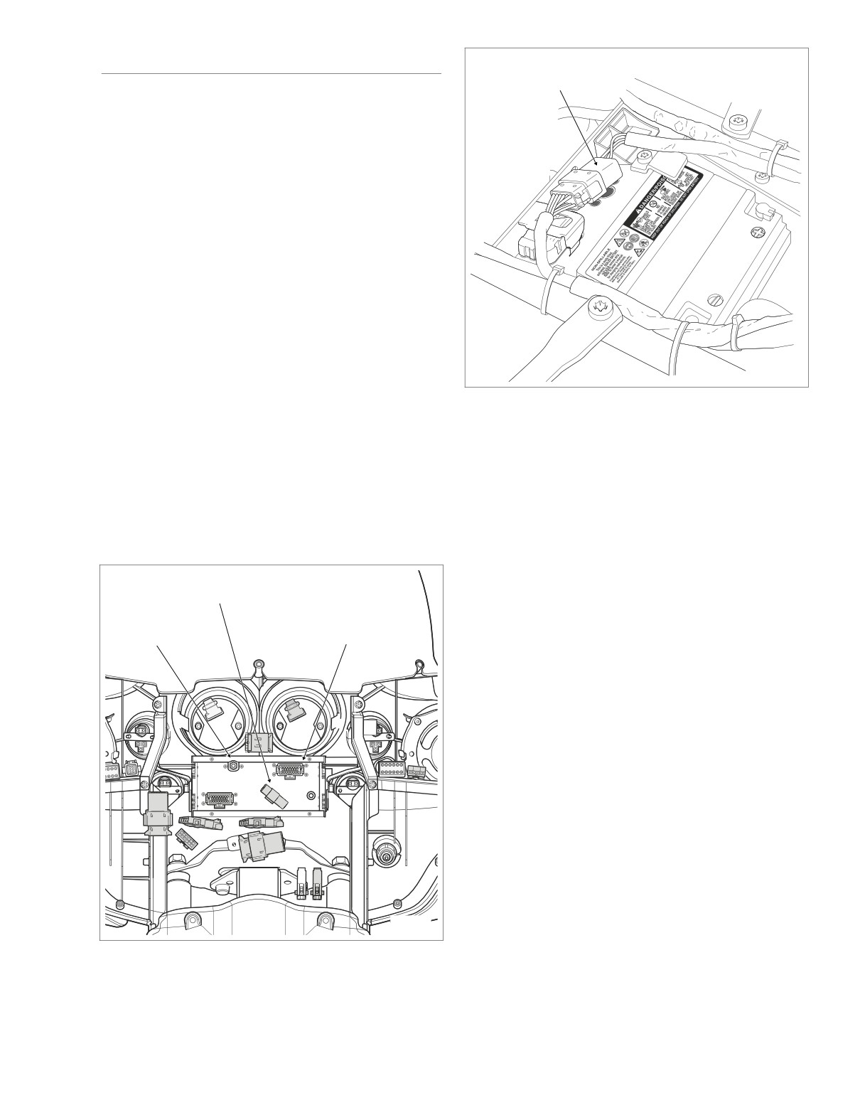
Console Pod
Connector [53]
REMOVAL
1.
Remove fuel tank. For carbureted models, see Section
4.7 FUEL TANK
(CARBURETED), COMPLETE
REMOVAL, FLHT/C. For fuel injected models, see Sec-
tion 9.4 FUEL TANK (FUEL INJECTED), COMPLETE
REMOVAL, FLHT/C/U/I, FLTRI.
2.
Remove right side saddlebag. See Section 2.25 SAD-
DLEBAG, REMOVAL.
3.
Gently pull side cover from frame downtubes (no tools
required).
4.
Repeat steps 2 and 3 on left side of motorcycle.
5.
Remove the outer fairing and windshield. See Section
2.29 UPPER FAIRING/WINDSHIELD
(FLHT/C/U),
OUTER FAIRING/WINDSHIELD, REMOVAL.
f2192x8x
6.
See Figure 8-174. Disconnect pin and socket halves of
Figure 8-175. Disconnect Console Pod Connector
the following connectors:
a. CB antenna cable connector [50], back of radio
(right side).
7.
Remove screw, ground wire ring terminal and P-clamp to
release main harness and audio harness from right side
b. Audio to interconnect harness connector
[6],
3-
of steering head.
place Deutsch (black); back of radio (right side).
8.
Carefully pull audio harness rearward under right side of
c. Radio connector [28], 23-place Amp (gray); back of
fairing cap allowing conduit and connectors to hang over
radio (left side).
top of engine guard.
9.
Carefully cut cable straps securing audio harness to
Audio to
frame backbone, left and right frame tubes, and luggage
Interconnect Harness [6]
rack rails. See Figure 8-177. Carefully cut cable straps
securing audio harness to main harness, if present.
CB Antenna
Radio [28]
10.
Remove flange nut (10 mm) from right side ground stud
Cable [50]
on upper frame crossmember. Remove audio harness
ground ring terminal.
11.
Release console pod connector [53],
12-place Mini-
Deutsch, from attachment clip anchored in hole at rear
of battery box. See Figure
8-175. Depress external
latches and use a rocking motion to separate pin and
socket halves.
12.
Remove trim
ring and gently pull on wire harness to
draw rear right speaker/passenger controls connector
[41], 6-place Mini-Deutsch, out of speaker box. Depress
external latch and use a rocking motion to separate pin
and socket halves.
13.
Open Tour-Pak. Open map pocket and remove acorn
nuts. Remove map pocket and molded liner from Tour-
Pak.
f2238x8x
14.
Separate pin and socket halves of CB antenna cable
connector [50]. Release cable from clip at bottom of
Figure 8-174.
Audio Harness Connectors
Tour-Pak. See Figure 8-176.
2005 Touring: Electrical
8-143
HOME
2.
See Figure 8-174. Standing at front of motorcycle, mate
pin and socket halves of the following wire harness con-
Grommet
nectors:
a. CB antenna cable connector [50], back of radio
Cable
(right side).
Clip
b. Audio to interconnect harness connector
[6],
3-
place Deutsch (black); back of radio (right side).
c. Radio connector [28], 23-place Amp (gray); back of
radio (left side).
3.
On right side of motorcycle, capture audio harness and
main harness in P-clamp. Install ground wire ring termi-
nal on screw and fasten P-clamp to right side of steering
head.
4.
Install audio harness ground ring terminal onto right side
ground stud on upper frame crossmember. Install flange
CB Antenna
nut (10 mm) and tighten to 50-90 in-lbs (5.7-10.2 Nm).
Cable Connector
f1467b2x
5.
Mate pin and socket halves of console pod connector
[53],
12-place Mini-Deutsch. Install connector onto
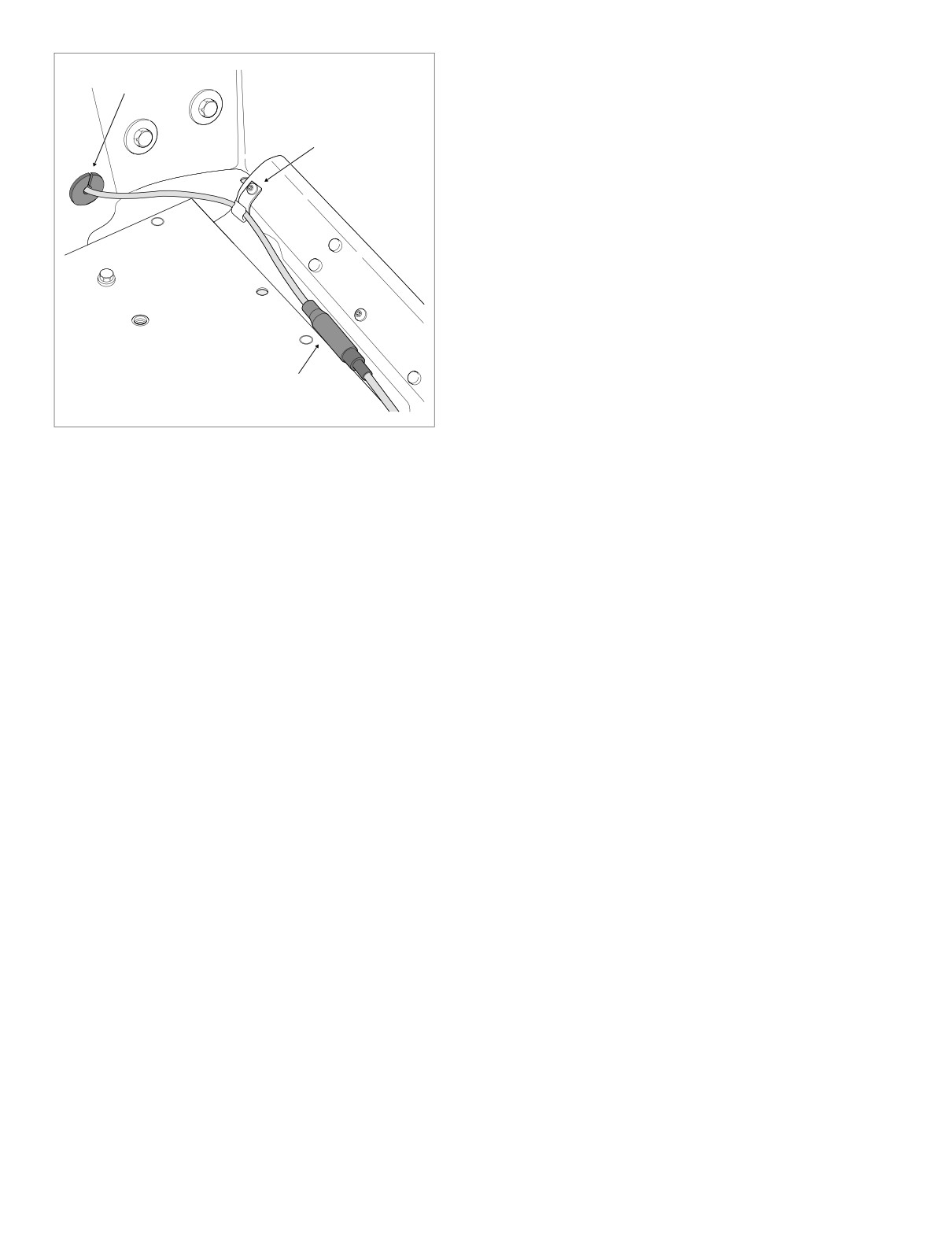
Figure 8-176. Disconnect CB Antenna Cable Connector
attachment clip anchored in hole at rear of battery box.
See Figure 8-175.
15. Pull right side grommet into Tour-Pak and remove from
6.
Mate pin and socket housings of rear right speaker/pas-
CB antenna cable. Feed CB antenna cable through hole
senger controls connector [41], 6-place Mini-Deutsch.
at front of Tour-Pak.
Feed connector back up into speaker box pressing trim
ring into hole.
16. Moving to opposite side of motorcycle, remove trim ring
and gently pull on wire harness to draw rear left speaker/
7.
Pass CB antenna cable connector [50] through hole at
passenger controls connector [42], 6-place Mini-Deut-
front of Tour-Pak. Capture cable in grommet. Install
sch, out of speaker box. Depress external latch and use
grommet in hole with the larger OD facing inside. See
a rocking motion to separate pin and socket halves.
Figure 8-176.
17. Release rear headset receptacle from bracket at bottom
8.
Mate pin and socket halves of CB antenna cable con-
of left side speaker box. Release spring from hole in
nector. Capture antenna cable in clip at bottom of Tour-
receptacle wire jacket.
Pak.
18. Remove audio harness from motorcycle.
9.
Moving to opposite side of motorcycle, mate pin and
socket housings of rear left speaker/passenger controls
connector [42], 6-place Mini-Deutsch. Feed connector
INSTALLATION
back up into speaker box pressing trim ring into hole.
10.
Attach spring to rear headset receptacle using hole in
1.
Place new audio harness on motorcycle following origi-
wire jacket. Capture headset receptacle in bracket at
nal routing. Note that the audio harness follows the
bottom of left side speaker box.
branches of the main harness as it is routed to the rear
left and right sides of the motorcycle.
11.
At front of top engine stabilizer bracket, install new 14
inch cable strap capturing frame backbone, audio har-
NOTE
ness and main harness. Tighten cable strap, but leave
loose enough so that one finger can be inserted
Specifically, from the front of the inner fairing, the audio har-
between strap and frame backbone. Do not over-
ness is routed under the fairing cap where it passes through
tighten. Cut any excess cable strap material.
a P-clamp on the right side of the steering head. The harness
then runs along the right side of the frame backbone, where
12.
Install remaining cables straps as shown in Figure 8-
a branch crosses to the left side at the main harness anchor
177.
in the center of the frame backbone. From this point, each
branch follows its respective side of the frame backbone, run-
13.
Install the outer fairing and windshield. See Section 2.29
ning along the inboard side of the upper frame tubes and
UPPER FAIRING/WINDSHIELD (FLHT/C/U), OUTER
then down the luggage rack rails.
FAIRING/WINDSHIELD, INSTALLATION.
8-144
2005 Touring: Electrical
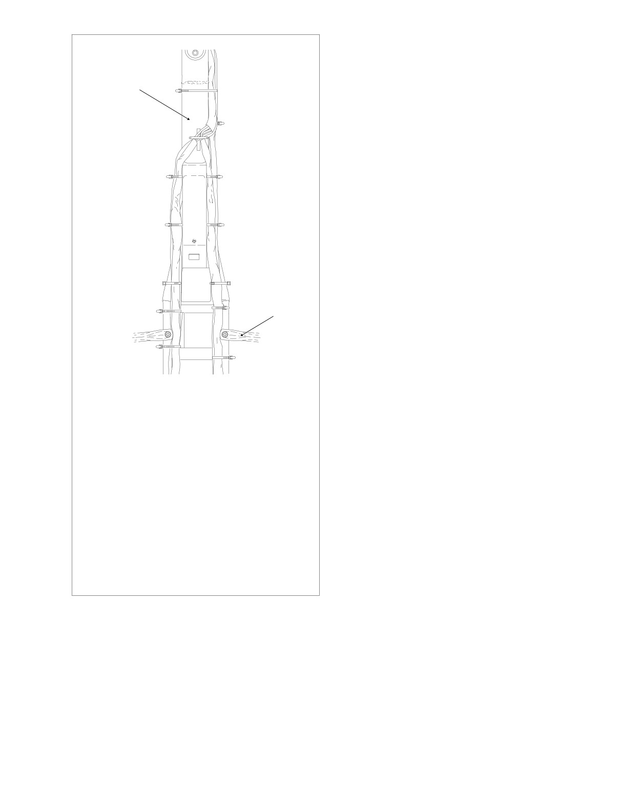
HOME
14. Align barbed studs in right side cover with grommets in
frame downtubes and push firmly into place (no tools
A = Anchored
required).
Frame
15. Install right side saddlebag. See Section 2.25 SADDLE-
Backbone
1
BAG, INSTALLATION.
16. Repeat steps 14 and 15 on left side of motorcycle.
17. Install fuel tank. For carbureted models, see Section 4.7
2 A
FUEL TANK (CARBURETED), INSTALLATION (AFTER
COMPLETE REMOVAL), FLHT/C. For fuel injected
models, see Section
9.4 FUEL TANK
(FUEL
INJECTED), INSTALLATION
(AFTER COMPLETE
8 A
3 A
REMOVAL), FLHT/C/U/I, FLTRI.
9 A
4 A
10 A
5 A
Saddlebag
11
6
Guard
12
7
f2225x8x
1
Captures main harness, cruise roll-off switch conduit,
audio harness (FLHTCUI only) and frame backbone.
2
Captures main harness and audio harness
(FLHTCUI
only). ANCHORED.
3
4
5 Captures main harness, audio harness (FLHTCUI only),
EFI/ignition harness, and conduit to fuel tank harness (all
models except FLHR/C/S). ANCHORED.
6
7
Captures audio harness (FLHTCUI only) and upper frame
tube.
8
9
Captures main harness and audio harness
(FLHTCUI
only). ANCHORED.
10
Captures main harness, audio harness (FLHTCUI only),
fuel vapor vent tube and console pod or instrument
console conduit. ANCHORED.
11
Captures main harness, audio harness (FLHTCUI only),
console pod or instrument console conduit and upper
frame tube.
12
Captures main harness, audio harness (FLHTCUI only),
console pod conduit (FLHTCUI only) and upper frame
tube.
Figure 8-177. Install Cable Straps
2005 Touring: Electrical
8-145
HOME
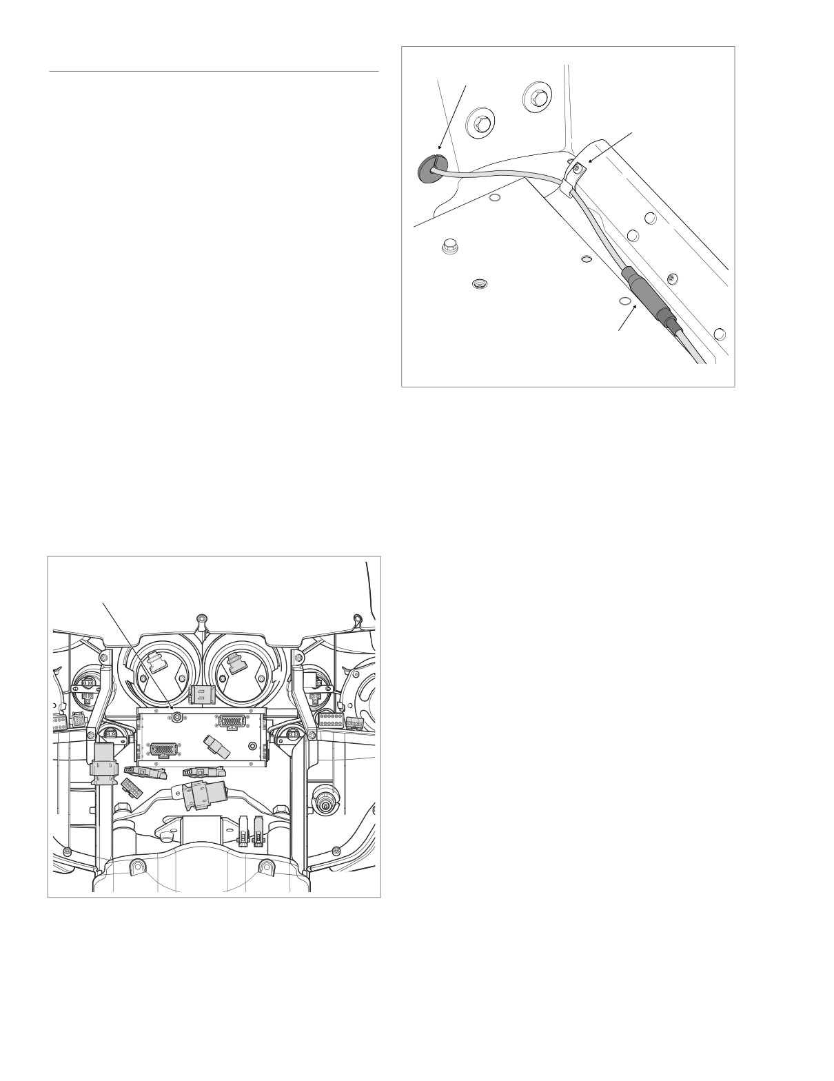
CB ANTENNA CABLE (FLHTCU)
Grommet
REMOVAL
Cable
Clip
1.
Remove fuel tank. For carbureted models, see Section
4.7 FUEL TANK
(CARBURETED), COMPLETE
REMOVAL, FLHT/C. For fuel injected models, see Sec-
tion 9.4 FUEL TANK (FUEL INJECTED), COMPLETE
REMOVAL, FLHT/C/U/I, FLTRI.
2.
Remove right side saddlebag. See Section 2.25 SAD-
DLEBAG, REMOVAL.
3.
Gently pull side cover from frame downtubes (no tools
required).
4.
Remove the outer fairing and windshield. See Section
2.29 UPPER FAIRING/WINDSHIELD
(FLHT/C/U),
OUTER FAIRING/WINDSHIELD, REMOVAL.
CB Antenna
5.
Locate CB antenna cable connector [50] at back of radio
Cable Connector
f1467b2x
(right side). Rotate knurled ring in a counterclockwise
direction to disconnect. See Figure 8-178. Carefully cut
cable where it exits audio harness conduit.
Figure 8-179. CB Antenna Cable Connector
(Tour-Pak)
6.
Remove screw, ground wire ring terminal and P-clamp to
release main harness and audio harness from right side
of steering head.
8.
Open Tour-Pak. Open map pocket and remove acorn
7.
Carefully cut cable straps securing audio harness to
nuts
(with flat washers). Remove map pocket and
frame backbone, right frame tube and luggage rack rail.
molded liner from Tour-Pak.
See Figure 8-181. Carefully cut cable straps securing
9.
Separate pin and socket halves of CB antenna cable
audio harness to main harness, if present.
connector [50]. Release cable from clip at bottom of
Tour-Pak. See Figure 8-179.
10. Pull right side grommet into Tour-Pak and remove from
CB Antenna
Cable [50]
CB antenna cable. Feed CB antenna cable through hole
at front of Tour-Pak.
11. Carefully cut CB antenna cable where it exits branch of
audio harness conduit.
INSTALLATION
1.
Place new CB antenna cable on motorcycle following
original routing. Note that the cable follows the branches
of the main harness and audio harness routed to the
rear right side of the motorcycle.
NOTE
Specifically, from the front of the inner fairing, the CB
antenna cable is routed under the fairing cap where it passes
through a P-clamp on the right side of the steering head.
f2238x8x
From this point, the cable follows the right side of the frame
backbone, runs along the inboard side of the upper frame
Figure 8-178. CB Antenna Cable Connector
tube and then continues down the luggage rack rail where it
(Inner Fairing)
passes through the hole at the front of the Tour-Pak.
8-146
2005 Touring: Electrical
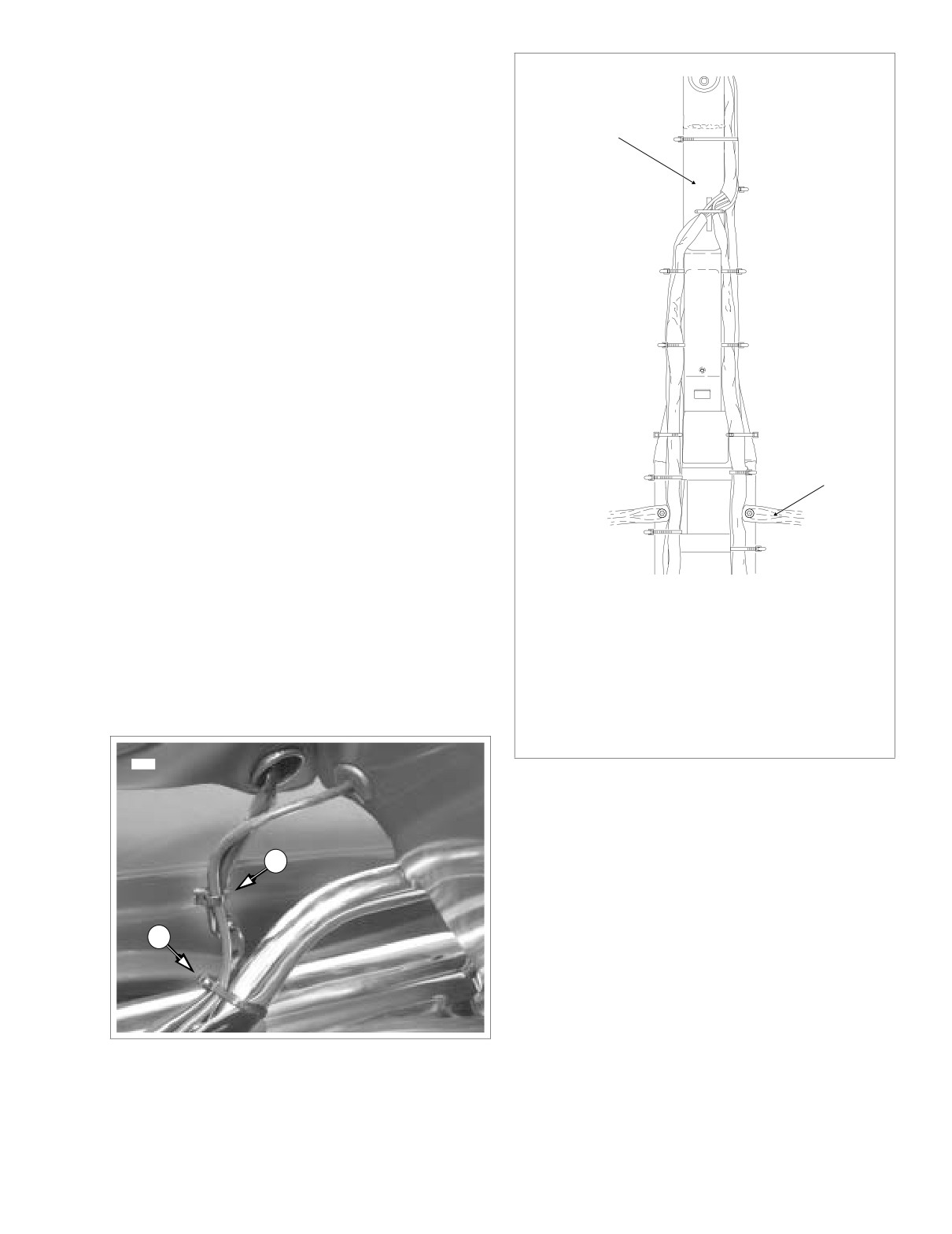
HOME
2.
Pass CB antenna cable connector [50] through hole at
front of Tour-Pak. Capture cable in grommet. Install
A = Anchored
grommet in hole with the larger OD facing inside. See
Figure 8-179.
Frame
Backbone
3.
Mate pin and socket halves of CB antenna cable con-
1
nector. Capture antenna cable in clip at bottom of Tour-
Pak.
2 A
4.
Install two new cable straps to secure CB antenna cable
to rear right speaker/passenger controls conduit and lug-
gage rack rail. See Figure 8-180.
5.
Install molded liner in Tour-Pak. Install map pocket and
3 A
secure using acorn nuts (with flat washers). Close Tour-
Pak.
6.
At front of inner fairing, rotate knurled ring to connect CB
4 A
antenna cable connector [50] to back of radio. See Fig-
ure 8-178.
7.
On right side of motorcycle, capture CB antenna cable,
audio harness and main harness in P-clamp. Install
ground wire ring terminal on screw and fasten P-clamp
5 A
to right side of steering head.
Saddlebag
6
Guard
8.
At front of top engine stabilizer bracket, install new 14
inch cable strap capturing frame backbone, CB antenna
cable, audio harness and main harness. Tighten cable
strap, but leave loose enough so that one finger can be
inserted between strap and frame backbone. Do not
7
overtighten. Cut any excess cable strap material.
f2225x8x
9.
Install remaining cables straps as shown in Figure 8-
181.
1
Captures main harness, cruise roll-off switch conduit,
audio harness (FLHTCUI only) and frame backbone.
10.
Install the outer fairing and windshield. See Section 2.29
2
Captures main harness and audio harness
(FLHTCUI
only). ANCHORED.
UPPER FAIRING/WINDSHIELD (FLHT/C/U), OUTER
3
4
5 Captures main harness, audio harness (FLHTCUI only),
FAIRING/WINDSHIELD, INSTALLATION.
EFI/ignition harness, and conduit to fuel tank harness (all
models except FLHR/C/S). ANCHORED.
6
7
Captures audio harness (FLHTCUI only) and upper frame
tube.
9426
Figure 8-181. Install Cable Straps
11. Align barbed studs in right side cover with grommets in
frame downtubes and push firmly into place (no tools
1
required).
12. Install right side saddlebag. See Section 2.25 SADDLE-
BAG, INSTALLATION.
2
13. Install fuel tank. For carbureted models, see Section 4.7
FUEL TANK (CARBURETED), INSTALLATION (AFTER
COMPLETE REMOVAL), FLHT/C. For fuel injected
models, see Section
9.4 FUEL TANK
(FUEL
INJECTED), INSTALLATION
(AFTER COMPLETE
REMOVAL), FLHT/C/U/I, FLTRI.
Figure 8-180. Secure CB Antenna Cable
2005 Touring: Electrical
8-147
HOME
IGNITION HARNESS
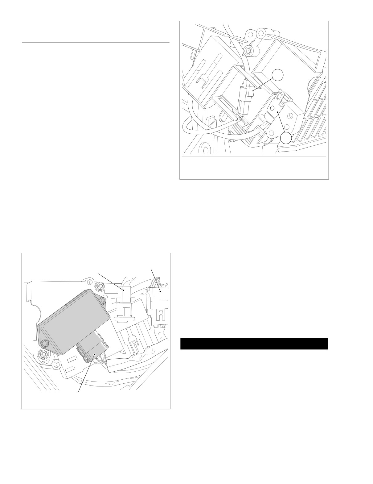
f1847x8x
(CARBURETED)
REMOVAL
1.
Remove fuel tank. See Section 4.7 FUEL TANK (CAR-
BURETED), COMPLETE REMOVAL, FLHT/C or
1
FLHR/S.
2.
Unthread bolt and remove battery positive cable (red)
from battery positive
(+) terminal.
(Battery negative
cable already removed under FUEL TANK, COMPLETE
REMOVAL.)
3.
Using a T40 TORX drive head, loosen bolt to move lip of
hold-down clamp off edge of battery. Remove battery
from battery box.
2
4.
Remove right side saddlebag. See Section 2.25 SAD-
DLEBAG, REMOVAL.
5.
Gently pull side cover from frame downtubes (no tools
1.
Vehicle Speed Sensor [65]
required).
2.
P&A Security Siren [142]
6.
Carefully cut cable straps to free ignition harness from
Figure 8-183. Electrical Bracket (Inboard Side)
right side of frame backbone, upper frame tube and
other wire harness bundles. See Figure 8-186.
7.
Remove ignition coil connector [83] and manifold abso-
8.
Remove ignition control module connector [10]. Depress
lute pressure sensor connector [80]. Pull external latch
external latches and use a rocking motion to separate
outward and use rocking motion to separate pin and
pin and socket halves. See Figure 8-182.
socket halves. Draw conduit and connectors to right side
of motorcycle as they are disconnected.
9.
Gently pull on data link connector [91] to disengage from
arms on electrical bracket.
10.
Pull main harness connector [8] from slot in electrical
Main Harness [8]
bracket. Depress external latches and use a rocking
Data Link [91]
motion to separate pin and socket halves.
11.
Remove two flange nuts to release electrical bracket
from studs on side of battery box.
12.
On inboard side of electrical bracket, disconnect vehicle
speed sensor connector [65]. Depress button on socket
housing and pull apart pin and socket halves. See Fig-
ure 8-183.
CAUTION
Damage to wires can result in electrical problems. Be
sure that rubber boot is present on threaded end of bat-
tery box TORX screw. Replace rubber boot if absent or
damaged. See Figure 8-184.
13. Note that ignition harness conduit runs forward of the
Ignition Control
front battery box TORX screw. Pull conduit to the rear of
Module [10]
f2191x8x
the screw, and then draw connectors and conduit down
right side of frame backbone into battery box.
Figure 8-182. Electrical Bracket (Under Right Side Cover)
8-148
2005 Touring: Electrical
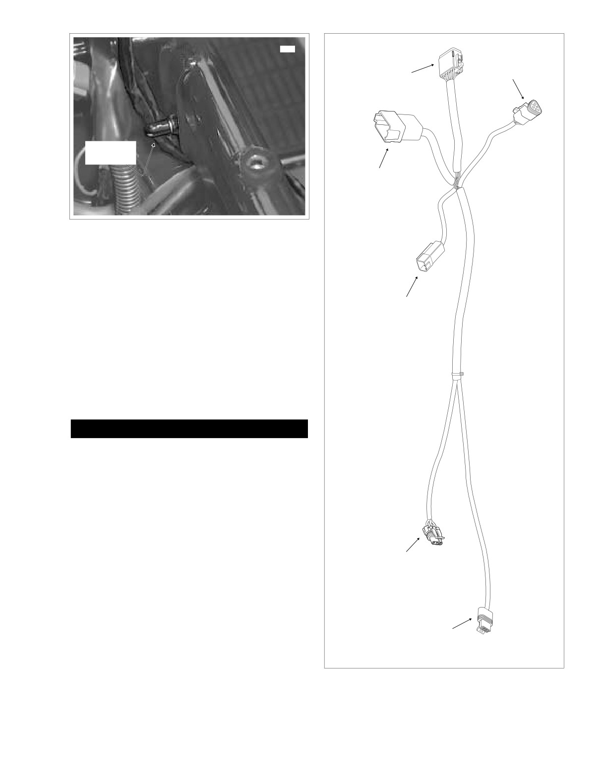
HOME
8321
Vehicle Speed
Ignition
Control Module
Sensor [65B]
[10B]
Rubber
Boot
Main Harness
[8A]
Figure 8-184. Remove Ignition Harness From Vehicle
14. Pull connectors and conduit out through opening at side
of battery box to remove ignition harness from motorcy-
cle.
Data Link
[91A]
INSTALLATION
1. Locate end of ignition harness terminating in two con-
nectors. See Figure 8-185.
2. Standing on right side of motorcycle, carefully feed con-
nectors and conduit through opening into battery box.
Pull up on harness and tuck conduit into space in front of
the battery box TORX screw.
CAUTION
Damage to wires can result in electrical problems. Be
sure that rubber boot is present on threaded end of bat-
tery box TORX screw. Replace rubber boot if absent or
damaged. See Figure 8-184.
3. Draw connectors and conduit up along right side of
frame backbone just below the main harness bundle.
4. Loosely install new cable straps to secure ignition har-
ness to right side of frame backbone, upper frame tube
and other wire harness bundles. See Figure 8-186.
Manifold Absolute
5. Feed ignition coil connector over the top engine stabi-
Pressure
lizer link to left side of motorcycle. Install ignition coil
Sensor [80B]
connector [83] onto left side of ignition coil.
6. Install manifold absolute pressure sensor connector [80].
7.
Returning to electrical bracket, mate pin and socket
Ignition
halves of vehicle speed sensor connector [65]. Route
Coil [83B]
siren and vehicle speed sensor connectors and conduit
on inboard side of electrical bracket as shown in Figure
f2226x8x
8-183.
Figure 8-185. Ignition Wire Harness Connectors
2005 Touring: Electrical
8-149