Harley Davidson 2013 Sportster Models. Service Manual - page 15
 

  Главная      Harley Davidson     Harley Davidson 2013 Sportster Models. Service Manual


Search            copyright infringement  


Content      ..     13      14      15      16     ..


Harley Davidson 2013 Sportster Models. Service Manual - page 15


INSTALLATION

TORQUE VALUE

FASTENER

81-88 Nm

60-65 ft-lbs

Axle, front, nut

55.6-65.1 Nm

41-48 ft-lbs

Axle, front, pinch screw: XR
1200X

38.0-51.6 Nm

28-38 ft-lbs

Brake caliper, front, mounting
bolt

27.1-33.9 Nm

20-25 ft-lbs

Brake line banjo bolt

1.0-2.0 Nm

9-17

in-lbs

Brake master cylinder, front,
reservoir cover screws

Direct contact of D.O.T. 4 brake fluid with eyes can cause
irritation. Avoid eye contact. In case of eye contact flush
with large amounts of water and get medical attention.
Swallowing large amounts of D.O.T. 4 brake fluid can cause
digestive discomfort. If swallowed, obtain medical atten-
tion. Use in well ventilated area. KEEP OUT OF REACH OF
CHILDREN. (00240a)

D.O.T. 4 brake fluid will damage painted and body panel
surfaces it comes in contact with. Always use caution and
protect surfaces from spills whenever brake work is per-
formed. Failure to comply can result in cosmetic damage.
(00239b)

NOTE

If DOT 4 BRAKE FLUID contacts painted surfaces, IMMEDI-
ATELY flush area with clear water.

1.

Align calipers to brake discs.

a.

Tighten axle nut to 60-65 ft-lbs (81-88 Nm).

b.

Loosen axle pinch screw nut.

c.

Position right fork leg against bearing spacer. Tighten
axle pinch screw to 41-48 ft-lbs (55.6-65.1 Nm).

2.

See

Figure 2-82

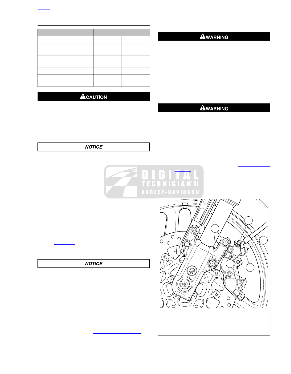
. Place brake caliper over brake disc with

bleeder valve (1) facing upwards. Install mounting bolts
(4) and tighten to 28-38 ft-lbs (38.0-51.6 Nm).

Avoid leakage. Be sure gaskets, banjo bolt(s), brake line
and caliper bore are clean and undamaged before
assembly. (00321a)

NOTE

Brake caliper housing has a positive stop for banjo fitting. When
tightening banjo bolt into brake caliper in the next step, rotate
banjo fitting clockwise until it contacts positive stop.

3.

Position a

new

washer (3) on each side of hydraulic brake

line banjo fitting (5). Insert banjo bolt (2) through washers
and fitting. Tighten to 20-25 ft-lbs (27.1-33.9 Nm).

4.

Bleed brake system. See

2.17 BLEEDING BRAKES

.

NOTE

Bleed both calipers.

A plugged or covered relief port can cause brake drag or
lock-up, which could lead to loss of control, resulting in
death or serious injury. (00288a)

5.

Verify operation of master cylinder relief port. With motor-
cycle positioned with master cylinder reservoir is level,
squeeze brake lever slowly with reservoir cover removed.
A slight spurt of fluid will break the surface if all internal
components are working properly.

6.

Install gasket and cover on master cylinder. Install screws.
Tighten to 9-17

in-lbs

(1.0-2.0 Nm).

After repairing the brake system, test brakes at low speed.
If brakes are not operating properly, testing at high speeds
can cause loss of control, which could result in death or
serious injury. (00289a)

7.

Test brake system.

a.

Turn ignition switch ON. Squeeze brake hand lever
to verify operation of the stop lamp.

b.

Test ride the motorcycle. If the brakes feel spongy,
bleed the system again. See

2.17 BLEEDING

BRAKES

.

NOTE

Avoid making hard stops for the first 100 mi (160 km) to allow
the new pads to become conditioned to the brake discs.

1

3

2

4

5

sm06932

1. Bleeder valve
2. Banjo bolt (metric)
3. Sealing washer
4. Mounting bolt (metric)
5. Banjo fitting

Figure 2-82. Front Caliper Assembly: XR 1200X

HOME

2013 Sportster Service: Chassis 2-57

2.11

REAR BRAKE MASTER CYLINDER: XL MODELS

GENERAL

The rear brake master cylinder is mounted transverse to the
centerline, beneath the rear fork pivot shaft assembly.

If the rear brake feels spongy or excessive pedal travel exists
or the brake does not work at all, proceed to Inspection.

NOTES

Use only CCI #20 BRAKE GREASE to lubricate master
cylinder bores, pistons, primary cups and secondary cups.

Use only KS62F assembly grease on caliper pistons and
piston seals.

Use only G40M BRAKE GREASE on the caliper pins and
boots.

Direct contact of D.O.T. 4 brake fluid with eyes can cause
irritation. Avoid eye contact. In case of eye contact flush
with large amounts of water and get medical attention.
Swallowing large amounts of D.O.T. 4 brake fluid can cause
digestive discomfort. If swallowed, obtain medical atten-
tion. Use in well ventilated area. KEEP OUT OF REACH OF
CHILDREN. (00240a)

D.O.T. 4 brake fluid will damage painted and body panel
surfaces it comes in contact with. Always use caution and
protect surfaces from spills whenever brake work is per-
formed. Failure to comply can result in cosmetic damage.
(00239b)

NOTE

If DOT 4 BRAKE FLUID contacts painted surfaces, IMMEDI-
ATELY flush area with clear water.

INSPECTION

1.

Check the fluid level in the rear brake reservoir. If it is low,
refill and bleed brake system. See

2.17 BLEEDING

BRAKES

.

2.

Check for fluid leaks in the brake line, around banjo fittings
or rear brake caliper piston or bleeder valve. Repair brake
system.

a.

Brake Line:

See

2.16 BRAKE LINES

.

b.

Brake Caliper:

See

2.14 REAR BRAKE CALIPER:

XL MODELS

.

3.

Check rear brake friction pads and disc for excessive wear
or damage. Replace as necessary.

a.

Brake Pads:

See

1.16 BRAKE PADS AND DISCS:

XL MODELS, Brake Pad Replacement: Rear

.

b.

Brake Discs:

See

2.5 WHEELS

.

4.

Check mechanical brake linkage from brake pedal to
master cylinder for damage. Replace as necessary.

a.

Models with Mid-Mount Controls:

See

2.40 RIDER

FOOT CONTROLS: XL MID-MOUNT CONTROLS

.

b.

Models with Forward Controls:

See

2.41 RIDER

FOOT CONTROLS: XL FORWARD CONTROLS

.

5.

Eliminate any air in the hydraulic brake assembly by
bleeding the system. See

2.17 BLEEDING BRAKES

.

If none of these conditions exist but the rear brake system does
not operate properly, the rear master cylinder is defective.
Replace or repair as necessary.

REMOVAL

Direct contact of D.O.T. 4 brake fluid with eyes can cause
irritation. Avoid eye contact. In case of eye contact flush
with large amounts of water and get medical attention.
Swallowing large amounts of D.O.T. 4 brake fluid can cause
digestive discomfort. If swallowed, obtain medical atten-
tion. Use in well ventilated area. KEEP OUT OF REACH OF
CHILDREN. (00240a)

1.

Drain rear brake master cylinder reservoir and remove
hose clamp and feed hose from master cylinder feed hose
port fitting. Discard hose clamp. See

2.13 REAR BRAKE

MASTER CYLINDER RESERVOIR

.

2.

Remove bleeder nipple cap from bleeder valve on rear
brake caliper. Install end of a length of 5/16 in (7.9 mm)
ID clear plastic tubing over caliper bleeder valve, while
placing free end in a suitable container.

NOTE

Dispose of brake fluid in accordance with local regulations.

3.

Open bleeder valve about 1/2-turn. Pump brake pedal to
drain brake fluid. Close bleeder valve but do not tighten.

4.

Models with EVAP Controls:

Remove EVAP canister

and mounting bracket. See

4.20 EVAPORATIVE EMIS-

SIONS CONTROL, Charcoal Canister

.

Wear safety glasses or goggles when removing or
installing retaining rings. Retaining rings can slip from the
pliers and could be propelled with enough force to cause
serious eye injury. (00312a)

NOTE

Use correct retaining ring pliers and correct tips. Verify that
tips are not excessively worn or damaged.

5.

See

Figure 2-83

Remove retaining ring (1) from clevis pin

(2). Remove clevis pin and disengage master cylinder
yoke (3) from bell crank (4). Discard retaining ring.

NOTE

Damaged banjo bolt surfaces will leak when reassembled.
Prevent damage to seating surfaces by carefully removing
brake line components.

HOME

2-58 2013 Sportster Service: Chassis

6.

Remove banjo bolt (5) and washers (6) from master cyl-
inder. Lift banjo fitting away from master cylinder. Discard
washers.

7.

Remove two screws (7) and two washers (8) securing rear
master cylinder to master cylinder mounting bracket (9)
and remove rear master cylinder.

8.

If it is necessary to remove master cylinder mounting
bracket:

a.

Remove retaining ring (10) and clevis pin (11). Dis-
connect bell crank from mounting bracket.

b.

Remove two screws (12).

c.

Remove screw (13) and mounting bracket.

7

3

5

8

11

2

1

6

13

6

4

10

12

9

sm07132

1. Retaining ring
2. Clevis pin
3. Yoke
4. Bell crank
5. Banjo bolt
6. Sealing washer
7. Screw
8. Washer
9. Mounting bracket
10. Retaining ring
11. Clevis pin
12. Screw
13. Screw

Figure 2-83. Rear Brake Master Cylinder

DISASSEMBLY

NOTES

Do not disassemble the rear master cylinder unless prob-
lems are being experienced. Discard all seals during the

disassembly procedure. Install a complete rebuild kit when
the unit is reassembled.

Clamp rear brake master cylinder in a vise by its mounting
bosses only. Use brass or aluminum jaw covers or other
protective device on vise jaws to prevent damage to
master cylinder.

1.

See

Figure 2-84

. Clamp rear brake master cylinder in a

vise with yoke (1) pointing up.

2.

Remove external boot (2). Remove spring pin (3) from
end of pushrod (4). Discard spring pin.

NOTE

Grip yoke by the edges with an adjustable wrench. Do not grip
yoke by the flats or the yoke may become deformed.

3.

Hold yoke with an adjustable wrench. Using an open-end
wrench, loosen shoulder nut. Remove yoke.

Wear safety glasses or goggles when removing or
installing spring. Spring tension can cause spring, attached
components and/or hand tools to fly out which could result
in death or serious injury. (00477c)

4.

Press down on spring retainer (5) to compress external
return spring (6). While spring is compressed, remove
shoulder nut from pushrod. Carefully release pressure on
external return spring. Remove spring retainer and external
return spring.

5.

Remove and discard inner boot (8).

NOTE

Do not remove boot collar nut and pushrod retainer from
pushrod.

Wear safety glasses or goggles when removing or
installing retaining rings. Retaining rings can slip from the
pliers and could be propelled with enough force to cause
serious eye injury. (00312a)

6.

See

Figure 2-86

. Thread shoulder nut back onto pushrod

several turns, to protect pushrod threads. Press down on
pushrod to compress piston spring (1). Remove retaining
ring (2).

7.

Remove pushrod (3) with boot collar nut (4) and pushrod
retainer (5), piston (6) with secondary cup (7), primary cup
(8) and piston spring. Discard retaining ring, piston with
secondary cup, primary cup and piston spring.

8.

Remove dust cover (9), retaining ring (10), feed port fitting
(11) and O-ring (12). Discard retaining ring and O-ring.

HOME

2013 Sportster Service: Chassis 2-59

7

2

6

3

5

8

4

1

sm06913a

1. Yoke
2. External boot
3. Spring pin
4. Pushrod
5. Spring retainer
6. External spring
7. Shoulder nut
8. Inner boot

Figure 2-84. Rear Brake Master Cylinder

1

2

sm01808

1. Incorrect
2. Correct

Figure 2-85. Tightening Yoke

7

5

2

9

11

4

1

10

12

3

6

8

sm06921

1. Piston spring
2. Retaining ring
3. Pushrod
4. Boot collar nut
5. Pushrod retainer
6. Piston
7. Secondary cup
8. Primary cup
9. Dust cover
10. Retaining ring
11. Feed port fitting
12. O-ring

Figure 2-86. Rear Brake Master Cylinder

CLEANING AND INSPECTION

Use denatured alcohol to clean brake system components.
Do not use mineral-based solvents (such as gasoline or
paint thinner), which will deteriorate rubber parts even
after assembly. Deterioration of these components can
cause brake failure, which could result in death or serious
injury. (00291a)

Compressed air can pierce the skin and flying debris from
compressed air could cause serious eye injury. Wear
safety glasses when working with compressed air. Never
use your hand to check for air leaks or to determine air
flow rates. (00061a)

1.

Blow out drilled passages and piston bore in master cyl-
inder body with low pressure compressed air from a clean
air supply. Do not use a wire or similar instrument to clean
drilled passages.

HOME

2-60 2013 Sportster Service: Chassis

2.

Carefully inspect all components.

a.

Inspect piston bore for damage. Replace as neces-
sary.

b.

Inspect outlet port that mates with brake line banjo
fitting. This is a critical sealing surface. Replace as
necessary.

3.

Verify that vent holes in master cylinder are completely
open and free of dirt or debris.

ASSEMBLY

TORQUE VALUE

FASTENER

14.7-19.6 Nm

130-173

in-lbs

Brake master cylinder, rear,
pushrod shoulder nut

NOTES

When assembling rear brake master cylinder, always use
new parts from the service parts kit. See the parts catalog.

Lubricate cylinder bore, cups and seals with CCI #20
BRAKE GREASE before assembly.

Stand master cylinder on wooden block or clean, lint-free
towel to protect seating surfaces.

1.

Coat

new

O-ring with DOT 4 BRAKE FLUID. Install O-ring

and feed port fitting into feed port on top of master cylinder.

Wear safety glasses or goggles when removing or
installing retaining rings. Retaining rings can slip from the
pliers and could be propelled with enough force to cause
serious eye injury. (00312a)

NOTE

Use correct retaining ring pliers and correct tips. Verify that
tips are not excessively worn or damaged.

2.

Secure with

new

retaining ring. Verify that retaining ring

is fully seated in groove.

3.

Slide dust cover onto feed port fitting. Press into place in
master cylinder feed port. Turn feed port fitting so it points
toward banjo fitting end of master cylinder body.

NOTE

Clamp rear brake master cylinder in a vise by its mounting
bosses only. Use brass jaw covers or other protective device
on vise jaws to prevent damage to master cylinder.

4.

Clamp master cylinder in a vise with banjo fitting end
pointing down.

5.

See

Figure 2-87

. Lubricate master cylinder bore,

new

piston (1) with

new

secondary cup (3), and

new

primary

cup (2) with CCI #20 BRAKE GREASE supplied in the
service parts kit.

Wear safety glasses or goggles when removing or
installing spring. Spring tension can cause spring, attached
components and/or hand tools to fly out which could result
in death or serious injury. (00477c)

6.

Press small end of

new

piston spring (4) onto mounting

boss (8) on piston (1).

7.

Slide piston/spring assembly, flared end of spring first,
into cylinder bore so that spring seats against counter bore
(recess) at bottom of cylinder.

8.

Apply approximately 0.1 g of G40M BRAKE GREASE to
ball end of pushrod (5). Insert ball end of pushrod into
cupped end of piston.

1

2

3

4

5

6

7

8

sm02308

1. Piston
2. Primary cup
3. Secondary cup
4. Piston spring
5. Pushrod
6. Boot collar nut
7. Pushrod retainer
8. Piston spring mounting boss

Figure 2-87. Rear Master Cylinder Piston, Pushrod and

Spring Assembly

Wear safety glasses or goggles when removing or
installing retaining rings. Retaining rings can slip from the
pliers and could be propelled with enough force to cause
serious eye injury. (00312a)

9.

Temporarily thread shoulder nut onto pushrod several
turns to protect pushrod threads. Press down on pushrod
to compress piston spring. Slide pushrod retainer down
into master cylinder bore.

10. Secure pushrod assembly with

new

retaining ring. Verify

that retaining ring is fully seated in groove. Remove
shoulder nut from pushrod.

11. See

Figure 2-88

. Apply approximately 0.1 g of G40M

BRAKE GREASE around groove (4) in boot collar nut (3).
Carefully slide inner boot (5) down onto pushrod (2) and
into end of master cylinder bore. Press lip of inner boot
down around groove in boot collar nut.

12. Install external return spring and spring retainer. Thread

shoulder nut shoulder-first onto pushrod several turns past
flats.

13. Thread yoke onto pushrod, at least 2-3 turns past flats.

Install

new

spring pin into end of pushrod.

HOME

2013 Sportster Service: Chassis 2-61

2

4

1

3

5

sm01810

1. Rear brake master cylinder assembly
2. Pushrod
3. Boot collar nut
4. Groove
5. Inner boot

Figure 2-88. Lubricating and Installing Inner Boot

14. See

Figure 2-89

Measure from centerline of clevis pin

hole (1) in yoke to centerline of master cylinder mounting
boss hole (2) closest to yoke.

15. Turn yoke on pushrod to 3.40-3.48 in (86.3-88.3 mm).

3

1

2

sm01811

1. Clevis pin hole
2. Mounting boss hole
3. 3.40-3.48 in (86.3-88.3 mm)

Figure 2-89. Adjusting Pushrod Length

NOTE

Grip yoke by the edges with adjustable wrench. Do not grip
yoke by the flats or the yoke may become deformed.

16. Holding yoke with an adjustable wrench, turn shoulder nut

back against yoke. Tighten to 130-173

in-lbs

(14.7-19.6

Nm).

17. See

Figure 2-90

Remove master cylinder assembly from

vise. Slide external boot (2) over yoke/pushrod assembly
and external return spring.

18. Install the external boot.

a.

Position external boot tabs (3) at the 3 o'clock and 9
o'clock position when master cylinder body (1) is held
upright. The drain hole is at bottom of boot when
master cylinder is mounted.

b.

Fit lip on large end of the external boot to groove in
end of master cylinder.

c.

Seat the spring retainer in groove in small end of
external boot.

2

4

5

1

3

sm01809

1. Rear master cylinder assembly
2. External boot
3. Tabs (2)
4. Feed port fitting
5. Banjo fitting hole

Figure 2-90. Assembled Rear Master Cylinder

INSTALLATION

TORQUE VALUE

FASTENER

23.1-29.9 Nm

17-22 ft-lbs

Brake master cylinder
mounting bracket, rear, screw:
XL Models

23.1-29.9 Nm

17-22 ft-lbs

Brake master cylinder
mounting bracket, rear, screw:
XL Models

23.1-29.9 Nm

17-22 ft-lbs

Brake master cylinder, rear,
mounting screw: XL Models

27.1-33.9 Nm

20-25 ft-lbs

Brake line banjo bolt

Wear safety glasses or goggles when removing or
installing retaining rings. Retaining rings can slip from the
pliers and could be propelled with enough force to cause
serious eye injury. (00312a)

NOTE

Use correct retaining ring pliers and correct tips. Verify that
tips are not excessively worn or damaged.

HOME

2-62 2013 Sportster Service: Chassis

1.

See

Figure 2-83

. Install mounting bracket (9):

a.

Attach mounting bracket to frame loosely with screws
(12, 13) and tighten two screws (12) to 17-22 ft-lbs
(23.1-29.9 Nm).

b.

Tighten screw (13) to 17-22 ft-lbs (23.1-29.9 Nm).

2.

Install bell crank (4) with clevis pin (11). Secure with

new

retaining ring (10).

3.

Install rear master cylinder assembly on mounting bracket
with screws (7) and washers (8). Tighten to 17-22 ft-lbs
(23.1-29.9 Nm).

4.

Fit yoke (3) onto bell crank (4). Install clevis pin (2) and
secure with

new

retaining ring (1).

NOTE

Master cylinder housing has a positive stop for banjo fitting.
When tightening banjo bolt into master cylinder in the next
step, rotate banjo fitting clockwise until it contacts positive stop.

5.

Position a

new

sealing washer (6) on each side of

hydraulic brake line banjo fitting. Insert banjo bolt (5)
through washers and fitting. Thread bolt into master cyl-
inder housing. Tighten to 20-25 ft-lbs (27.1-33.9 Nm).

6.

Install rear brake master cylinder feed hose on master
cylinder feed hose port fitting. Secure with

new

hose

clamp. See

2.13 REAR BRAKE MASTER CYLINDER

RESERVOIR

.

7.

Models with EVAP Controls:

Install the EVAP canister

and mounting bracket. See

4.20 EVAPORATIVE EMIS-

SIONS CONTROL, Charcoal Canister

.

Direct contact of D.O.T. 4 brake fluid with eyes can cause
irritation. Avoid eye contact. In case of eye contact flush
with large amounts of water and get medical attention.
Swallowing large amounts of D.O.T. 4 brake fluid can cause
digestive discomfort. If swallowed, obtain medical atten-
tion. Use in well ventilated area. KEEP OUT OF REACH OF
CHILDREN. (00240a)

D.O.T. 4 brake fluid will damage painted and body panel
surfaces it comes in contact with. Always use caution and
protect surfaces from spills whenever brake work is per-
formed. Failure to comply can result in cosmetic damage.
(00239b)

NOTES

If DOT 4 brake fluid contacts painted surfaces, IMMEDI-
ATELY flush area with clear water.

Rear brake master cylinder reservoir must be in a level
position when filling and checking fluid level.

Reservoir cover may be removed from rear brake master
cylinder reservoir to more easily verify fluid level in reser-
voir.

Use only DOT 4 BRAKE FLUID from a sealed container.

Do not overfill reservoir. Do not reuse old brake fluid.

8.

Position motorcycle upright (not resting on jiffy stand).

9.

Remove reservoir cap.

10. Fill rear master cylinder reservoir with DOT 4 brake fluid

until the fluid level reaches the UPPER mark on the
reservoir.

11. Bleed brake system. See

2.17 BLEEDING BRAKES

.

Be sure that all lights and switches operate properly before
operating motorcycle. Low visibility of rider can result in
death or serious injury. (00316a)

12. Test operation of the stop lamp.

After servicing brakes and before moving motorcycle,
pump brakes to build brake system pressure. Insufficient
pressure can adversely affect brake performance, which
could result in death or serious injury. (00279a)

After repairing the brake system, test brakes at low speed.
If brakes are not operating properly, testing at high speeds
can cause loss of control, which could result in death or
serious injury. (00289a)

13. Test ride motorcycle at low speed.

HOME

2013 Sportster Service: Chassis 2-63

2.12

REAR BRAKE MASTER CYLINDER: XR 1200X

GENERAL

The rear brake master cylinder is mounted to the right side
rider footrest/rear brake pedal bracket.

If the rear brake feels spongy or excessive pedal travel exists
or the brake does not work at all, proceed with Inspection which
follows.

Direct contact of D.O.T. 4 brake fluid with eyes can cause
irritation. Avoid eye contact. In case of eye contact flush
with large amounts of water and get medical attention.
Swallowing large amounts of D.O.T. 4 brake fluid can cause
digestive discomfort. If swallowed, obtain medical atten-
tion. Use in well ventilated area. KEEP OUT OF REACH OF
CHILDREN. (00240a)

D.O.T. 4 brake fluid will damage painted and body panel
surfaces it comes in contact with. Always use caution and
protect surfaces from spills whenever brake work is per-
formed. Failure to comply can result in cosmetic damage.
(00239b)

NOTE

If DOT 4 brake fluid contacts painted surfaces, IMMEDIATELY
flush area with clear water.

INSPECTION

1.

Check the level of fluid in the rear brake reservoir. If it is
low, refill and bleed brake system. See

2.17 BLEEDING

BRAKES

.

2.

Check for fluid leaks in the brake line, around banjo fittings
or rear brake caliper piston or bleeder valve. Repair and
bleed brake system.

a.

For

brake

line

replacement

procedure,

see

2.16 BRAKE LINES

.

b.

To repair rear brake caliper, see procedure in

2.15 REAR BRAKE CALIPER: XR 1200X

.

c.

See

2.17 BLEEDING BRAKES

for hydraulic brake

system bleeding procedure.

3.

Check rear brake friction pads and disc for excessive wear
or damage. Replace as necessary.

a.

See

1.17 BRAKE PADS AND DISCS: XR 1200X

for

specifications.

b.

See

1.17 BRAKE PADS AND DISCS: XR 1200X,

Brake Pad Replacement: Rear

for brake pad

replacement procedure.

c.

See

2.5 WHEELS

for brake disc replacement pro-

cedure.

4.

Eliminate any air in the hydraulic brake assembly by
bleeding the system. See

2.17 BLEEDING BRAKES

.

If none of these conditions exist but the rear brake system does
not operate properly, repair or replace as necessary.

REMOVAL

Direct contact of D.O.T. 4 brake fluid with eyes can cause
irritation. Avoid eye contact. In case of eye contact flush
with large amounts of water and get medical attention.
Swallowing large amounts of D.O.T. 4 brake fluid can cause
digestive discomfort. If swallowed, obtain medical atten-
tion. Use in well ventilated area. KEEP OUT OF REACH OF
CHILDREN. (00240a)

1.

See

Figure 2-91

Drain rear brake master cylinder reservoir

(7) and remove feed hose (8) from master cylinder feed
hose port fitting. Discard hose clamp. See

2.13 REAR

BRAKE MASTER CYLINDER RESERVOIR

.

2.

Install end of a length of 5/16 in (7.9 mm) ID clear plastic
tubing over rear caliper bleeder valve and place free end
of tubing in a suitable container.

3.

Open bleeder valve about 1/2-turn. Pump brake pedal to
drain brake fluid. Close bleeder valve but do not tighten.

NOTE

Dispose of brake fluid in accordance with local regulations.

Wear safety glasses or goggles when removing or
installing retaining rings. Retaining rings can slip from the
pliers and could be propelled with enough force to cause
serious eye injury. (00312a)

4.

Remove retaining ring (1) from clevis pin (2). Remove
clevis pin and disengage master cylinder yoke (3) from
brake pedal. Discard retaining ring.

NOTE

Damaged banjo bolt surfaces will leak when reassembled.
Prevent damage to seating surfaces by carefully removing
brake line components.

5.

Remove banjo bolt (6) and washers (5). Lift banjo fitting
away from master cylinder. Discard washers.

6.

Remove two screws (4) securing rear master cylinder to
master cylinder mounting bracket and remove rear master
cylinder.

7.

If it is necessary to remove master cylinder/footpeg
mounting bracket, remove fasteners (9). See

2.42 RIDER

FOOT CONTROLS: XR 1200X

.

HOME

2-64 2013 Sportster Service: Chassis

1

2

3

6

5

4

7

8

9

sm05287a

1. Retaining ring
2. Clevis pin
3. Yoke
4. Screw and washer (2)
5. Washer (2)
6. Banjo bolt
7. Reservoir
8. Feed hose
9. Fastener (2)

Figure 2-91. Rear Brake Master Cylinder and Reservoir

DISASSEMBLY

NOTES

Do not disassemble the rear master cylinder unless prob-
lems are being experienced. Discard all seals during the
disassembly procedure. Install a complete rebuild kit when
the unit is reassembled.

Clamp rear brake master cylinder in a vise by its mounting
bosses only. Use brass or aluminum jaw covers or other
protective device on vise jaws to prevent damage to
master cylinder.

1.

See

Figure 2-92

. Clamp rear brake master cylinder in a

vise with yoke pointing up.

NOTE

Grip yoke by the edges with an adjustable wrench. Do not grip
yoke by the flats or the yoke may become deformed.

2.

Hold yoke with an adjustable wrench. Using an open-end
wrench, loosen shoulder nut. Remove yoke.

3.

See

Figure 2-93

. Remove nut (4) from pushrod (5).

4.

Remove and discard boot (6).

Wear safety glasses or goggles when removing or
installing retaining rings. Retaining rings can slip from the
pliers and could be propelled with enough force to cause
serious eye injury. (00312a)

NOTES

Do not remove boot collar nut from pushrod.

Use correct retaining ring pliers and correct tips. Verify
that tips are not excessively worn or damaged.

5.

Thread nut (4) back onto pushrod several turns, to protect
pushrod threads.

6.

Press down on pushrod to compress piston spring (10).
Remove retaining ring (7), pushrod (5) with boot collar nut,
piston (8) with secondary cup, primary cup (9) and piston
spring (10). Discard retaining ring, piston/cup assembly
and piston spring.

7.

Remove dust cover (12), retaining ring (13), feed port fitting
(15) and O-ring (14). Discard retaining ring and O-ring.

1

2

sm05298a

1. Incorrect
2. Correct

Figure 2-92. Holding Yoke

HOME

2013 Sportster Service: Chassis 2-65

3

4

7

2

5

14

8

12

13

15

10

6

1

11

9

sm06771

9.

1.

Primary cup

Retaining ring

2.

10.

Clevis pin

Piston spring

11.

3.

Retaining clip

Yoke

4.

12.

Nut

Dust cover

13.

5.

Pushrod retainer

Pushrod

6.

14.

Boot

O-ring

15.

7.

Feed port fitting

Retaining ring

8. Piston

Figure 2-93. Rear Brake Master Cylinder

CLEANING, INSPECTION AND REPAIR

Use denatured alcohol to clean brake system components.
Do not use mineral-based solvents (such as gasoline or
paint thinner), which will deteriorate rubber parts even
after assembly. Deterioration of these components can
cause brake failure, which could result in death or serious
injury. (00291a)

Compressed air can pierce the skin and flying debris from
compressed air could cause serious eye injury. Wear
safety glasses when working with compressed air. Never
use your hand to check for air leaks or to determine air
flow rates. (00061a)

1.

Thoroughly clean master cylinder body and all brake
system components. Blow out drilled passages and piston
bore with low pressure compressed air from a clean air
supply. Do not use a wire or similar instrument to clean
drilled passages.

2.

Carefully inspect all parts for wear or damage and replace
as necessary.

a.

Inspect piston bore in master cylinder housing for
scratches, grooves, scoring, pitting or corrosion.
Replace housing if any of these conditions are found.

b.

Inspect outlet port that mates with brake line banjo
fitting. This is a critical sealing surface. If necessary,
replace housing.

3.

Verify that vent holes in master cylinder are completely
open and free of dirt or debris.

ASSEMBLY

TORQUE VALUE

FASTENER

14.7-19.6 Nm

130-173

in-lbs

Brake master cylinder, rear,
pushrod nut: XR 1200X

NOTES

When assembling rear brake master cylinder, always use
new parts from the service parts kit. Consult the PARTS
CATALOG for the correct kit part number.

CCI #20 BRAKE GREASE is recommended for lubrication
of cylinder bore, cups and seals prior to assembly.

Stand master cylinder on wooden block or clean, lint-free
towel to protect seating surfaces.

Wear safety glasses or goggles when removing or
installing retaining rings. Retaining rings can slip from the
pliers and could be propelled with enough force to cause
serious eye injury. (00312a)

NOTE

Use correct retaining ring pliers and correct tips. Verify that
tips are not excessively worn or damaged.

1.

See

Figure 2-93

. Coat

new

O-ring (14) with DOT 4 BRAKE

FLUID. Install O-ring and feed port fitting (15) into feed
port on master cylinder body. Secure with

new

retaining

ring (13). Verify that retaining ring is fully seated in groove.

2.

Slide dust cover (12) onto feed port fitting and press into
place in master cylinder feed port.

NOTE

Clamp rear brake master cylinder body in a vise by its mounting
bosses only. Use brass jaw covers or other protective device
on vise jaws to prevent damage to master cylinder.

3.

Clamp master cylinder in a vise with banjo fitting end
pointing down.

4.

See

Figure 2-94

Lubricate master cylinder bore,

new

piston (1) with

new

secondary cup (3), and

new

primary

cup (2) with CCI #20 BRAKE GREASE supplied in the
service parts kit.

HOME

2-66 2013 Sportster Service: Chassis

Wear safety glasses or goggles when removing or
installing spring. Spring tension can cause spring, attached
components and/or hand tools to fly out which could result
in death or serious injury. (00477c)

5.

Press small end of

new

piston spring (4) onto mounting

boss (8) on piston.

1

2

3

4

5

6

7

8

sm05294

1. Piston
2. Primary cup
3. Secondary cup
4. Piston spring
5. Pushrod
6. Boot collar nut
7. Pushrod retainer
8. Piston spring mounting boss

Figure 2-94. Rear Master Cylinder Piston, Pushrod and

Spring Assembly

6.

Slide piston/spring assembly, flared end of spring first,
into cylinder bore so that spring seats against counter bore
(recess) at bottom of cylinder.

7.

Apply approximately 0.1 g of G40M BRAKE GREASE to
ball end of pushrod.

Wear safety glasses or goggles when removing or
installing retaining rings. Retaining rings can slip from the
pliers and could be propelled with enough force to cause
serious eye injury. (00312a)

NOTE

Use correct retaining ring pliers and correct tips. Verify that
tips are not excessively worn or damaged.

8.

See

Figure 2-93

. Temporarily thread nut (4) onto pushrod

(5) several turns to protect pushrod threads.

9.

Insert pushrod into master cylinder body. Press down on
pushrod to compress piston spring (10). Slide pushrod
retainer down into master cylinder bore and hold in place.

10. Secure pushrod assembly with

new

retaining ring (7).

Verify that retaining ring is fully seated in groove. Remove
nut (4) from pushrod.

11. Apply approximately 0.1 g of G40M BRAKE GREASE

around groove in boot collar nut. Carefully slide boot (6)
down onto pushrod and into end of master cylinder bore.
Press lip of boot down around groove in boot collar nut.

12. Thread nut (4) onto pushrod (5), several turns past flats.

13. Thread yoke (3) onto pushrod, at least 2-3 turns past flats.

14. See

Figure 2-95

. Measure distance (3) from centerline of

clevis pin hole (1) in yoke to centerline of master cylinder
mounting boss hole (2) closest to yoke. This distance must
be 2.64-2.76 in (67.1-70.1 mm). Adjust yoke until this dis-
tance is obtained.

NOTE

Grip yoke by the edges with adjustable wrench. do not grip
yoke by the flats or the yoke may become deformed.

15. While holding yoke with an adjustable wrench, turn

shoulder nut back against yoke. Tighten to 130-173

in-lbs

(14.7-19.6 Nm).

16. Remove master cylinder assembly from vise.

1

2

3

sm05299

1. Clevis pin hole
2. Mounting boss hole
3. Adjustment distance

Figure 2-95. Adjusting Pushrod Length

INSTALLATION

TORQUE VALUE

FASTENER

8.1-10.9 Nm

72-96

in-lbs

Brake master cylinder, rear,
mounting screw: XR 1200X

27.1-33.9 Nm

20-25 ft-lbs

Brake line banjo bolt

Wear safety glasses or goggles when removing or
installing retaining rings. Retaining rings can slip from the
pliers and could be propelled with enough force to cause
serious eye injury. (00312a)

HOME

2013 Sportster Service: Chassis 2-67

1.

See

Figure 2-91

Assemble and install master cyl-

inder/footpeg mounting bracket if it was removed. See

2.42 RIDER FOOT CONTROLS: XR 1200X

.

2.

Install rear master cylinder assembly to mounting bracket
with screws and washers (4). Tighten to 72-96

in-lbs

(8.1-

10.9 Nm).

3.

Fit yoke (3) onto foot pedal. Install clevis pin (2). Secure
with

new

retaining ring (1).

NOTE

Master cylinder housing has a positive stop for banjo fitting.
When tightening banjo bolt into master cylinder in the next
step, rotate banjo fitting clockwise until it contacts positive stop.

4.

Position a

new

washer (5) on each side of hydraulic brake

line banjo fitting. Insert banjo bolt (6) through washers and
fitting. Thread banjo bolt into master cylinder housing.
Tighten to 20-25 ft-lbs (27.1-33.9 Nm).

5.

Install rear brake master cylinder feed hose (8) on master
cylinder feed hose port fitting. Secure with

new

hose

clamp.

Direct contact of D.O.T. 4 brake fluid with eyes can cause
irritation. Avoid eye contact. In case of eye contact flush
with large amounts of water and get medical attention.
Swallowing large amounts of D.O.T. 4 brake fluid can cause
digestive discomfort. If swallowed, obtain medical atten-
tion. Use in well ventilated area. KEEP OUT OF REACH OF
CHILDREN. (00240a)

D.O.T. 4 brake fluid will damage painted and body panel
surfaces it comes in contact with. Always use caution and
protect surfaces from spills whenever brake work is per-
formed. Failure to comply can result in cosmetic damage.
(00239b)

NOTES

If DOT 4 brake fluid contacts painted surfaces, IMMEDI-
ATELY flush area with clear water.

Rear brake master cylinder reservoir must be in a level
position when filling and checking fluid level.

Reservoir cover may be removed from rear brake master
cylinder reservoir to more easily verify fluid level in reser-
voir.

Use only DOT 4 BRAKE FLUID from a sealed container.

Do not overfill reservoir. Do not reuse old brake fluid.

6.

Position motorcycle upright (not resting on jiffy stand).

7.

See

Figure 2-96

Remove reservoir cap (2).

8.

Fill rear master cylinder reservoir (1) with DOT 4 BRAKE
FLUID until the fluid level reaches the UPPER mark (3)
on the reservoir.

9.

Bleed brake system. See

2.17 BLEEDING BRAKES

.

10. Turn ignition switch ON. Test operation of stop lamp.

After servicing brakes and before moving motorcycle,
pump brakes to build brake system pressure. Insufficient
pressure can adversely affect brake performance, which
could result in death or serious injury. (00279a)

After repairing the brake system, test brakes at low speed.
If brakes are not operating properly, testing at high speeds
can cause loss of control, which could result in death or
serious injury. (00289a)

11. Test ride motorcycle at low speed. If brake feels spongy,

repeat bleeding procedure.

2

1

3

4

sm05262a

1. Reservoir
2. Reservoir cap
3. Upper fluid level
4. Lower fluid level

Figure 2-96. Rear Brake Master Cylinder Reservoir: XR

1200X

HOME

2-68 2013 Sportster Service: Chassis

2.13

REAR BRAKE MASTER CYLINDER RESERVOIR

REMOVAL: XL MODELS

Direct contact of D.O.T. 4 brake fluid with eyes can cause
irritation. Avoid eye contact. In case of eye contact flush
with large amounts of water and get medical attention.
Swallowing large amounts of D.O.T. 4 brake fluid can cause
digestive discomfort. If swallowed, obtain medical atten-
tion. Use in well ventilated area. KEEP OUT OF REACH OF
CHILDREN. (00240a)

D.O.T. 4 brake fluid will damage painted and body panel
surfaces it comes in contact with. Always use caution and
protect surfaces from spills whenever brake work is per-
formed. Failure to comply can result in cosmetic damage.
(00239b)

NOTE

If DOT 4 brake fluid contacts painted surfaces, IMMEDIATELY
flush area with clear water.

1.

Position motorcycle upright on suitable lift.

2.

See

Figure 2-97

Grasp reservoir cover (2) and gently pull

straight out from reservoir (1).

3.

Remove screw with captive washer (3).

4.

Remove reservoir cap (4). Hold reservoir upside down
over a suitable container and drain brake fluid.

NOTE

Dispose of brake fluid in accordance with local regulations.

5.

Loosen hose clamp (5). Pull feed hose (6) from reservoir.
Slide hose clamp off free end of feed hose.

6.

See

Figure 2-98

. Slide feed hose (2) down through clamp

(3). Hold free end of hose down over container and drain
any brake fluid remaining in hose.

7.

Loosen hose clamp (4). Pull feed hose off feed hose port
(5) on master cylinder (1).

8.

Cover feed hose port with a clean, lint-free cloth to keep
dirt and debris out of master cylinder.

2

1

5

6

4

3

sm01331

1. Rear brake master cylinder reservoir
2. Reservoir cover
3. Mounting screw with captive washer
4. Reservoir cap
5. Hose clamp
6. Master cylinder feed hose

Figure 2-97. Reservoir Mount

HOME

2013 Sportster Service: Chassis 2-69

3

2

1

4

5

sm01332

1. Rear brake master cylinder
2. Master cylinder feed hose
3. Clamp
4. Hose clamp
5. Feed hose port

Figure 2-98. Master Cylinder Feed Hose

INSTALLATION: XL MODELS

TORQUE VALUE

FASTENER

2.3-2.8 Nm

20-25

in-lbs

Brake master cylinder reser-
voir, rear, mounting screw

Direct contact of D.O.T. 4 brake fluid with eyes can cause
irritation. Avoid eye contact. In case of eye contact flush
with large amounts of water and get medical attention.
Swallowing large amounts of D.O.T. 4 brake fluid can cause
digestive discomfort. If swallowed, obtain medical atten-
tion. Use in well ventilated area. KEEP OUT OF REACH OF
CHILDREN. (00240a)

D.O.T. 4 brake fluid will damage painted and body panel
surfaces it comes in contact with. Always use caution and
protect surfaces from spills whenever brake work is per-
formed. Failure to comply can result in cosmetic damage.
(00239b)

NOTE

If DOT 4 BRAKE FLUID contacts painted surfaces, IMMEDI-
ATELY flush area with clear water.

1.

See

Figure 2-98

. Slide end of feed hose (2) onto feed hose

port (5) on master cylinder (1). Secure feed hose to fitting
with hose clamp (4).

2.

Slide free end of feed hose up through clamp (3).

3.

See

Figure 2-97

Slide hose clamp (5) onto free end of

feed hose (6).

4.

Push feed hose onto fitting on reservoir (1). Secure with
a hose clamp.

5.

Install reservoir using screw with captive washer (3).
Tighten to 20-25

in-lbs

(2.3-2.8 Nm).

NOTES

Level the rear brake master cylinder reservoir.

Use only DOT 4 BRAKE FLUID from a sealed container.

Do not overfill reservoir. Do not reuse old brake fluid.

6.

Position motorcycle upright (not resting on jiffy stand). Fill
master cylinder reservoir with DOT 4 BRAKE FLUID until
the fluid level reaches the UPPER mark on the reservoir.

7.

Bleed brake system. See

2.17 BLEEDING BRAKES

.

8.

Install reservoir cover (2).

9.

Verify tail lamp, and stop lamp.

10. Test ride motorcycle. If brake feels spongy, repeat bleeding

procedure.

REMOVAL: XR 1200X

Direct contact of D.O.T. 4 brake fluid with eyes can cause
irritation. Avoid eye contact. In case of eye contact flush
with large amounts of water and get medical attention.
Swallowing large amounts of D.O.T. 4 brake fluid can cause
digestive discomfort. If swallowed, obtain medical atten-
tion. Use in well ventilated area. KEEP OUT OF REACH OF
CHILDREN. (00240a)

D.O.T. 4 brake fluid will damage painted and body panel
surfaces it comes in contact with. Always use caution and
protect surfaces from spills whenever brake work is per-
formed. Failure to comply can result in cosmetic damage.
(00239b)

NOTE

If DOT 4 brake fluid contacts painted surfaces, IMMEDIATELY
flush area with clear water.

1.

Position motorcycle upright on suitable lift.

2.

See

Figure 2-99

Loosen reservoir cap (2).

3.

Remove screw (6).

4.

Remove reservoir cap (2). Hold reservoir upside down
over a suitable container and drain brake fluid.

5.

Loosen hose clamp (3) and pull feed hose (4) from reser-
voir. Slide hose clamp off free end of feed hose.

6.

Loosen hose clamp (5) and pull feed hose off master cyl-
inder. Cover feed hose port with a clean, lint-free cloth to
keep dirt and debris out of master cylinder.

HOME

2-70 2013 Sportster Service: Chassis

2

1

3

4

6

5

sm05303

1. Rear brake master cylinder reservoir
2. Reservoir cap
3. Hose clamp
4. Feed hose
5. Hose clamp (master cylinder)
6. Screw

Figure 2-99. Rear Brake Master Cylinder Reservoir: XR

1200X

INSTALLATION: XR 1200X

TORQUE VALUE

FASTENER

4.1-6.8 Nm

36-60

in-lbs

Brake master cylinder reser-
voir, rear, mounting screw

Direct contact of D.O.T. 4 brake fluid with eyes can cause
irritation. Avoid eye contact. In case of eye contact flush
with large amounts of water and get medical attention.
Swallowing large amounts of D.O.T. 4 brake fluid can cause
digestive discomfort. If swallowed, obtain medical atten-
tion. Use in well ventilated area. KEEP OUT OF REACH OF
CHILDREN. (00240a)

D.O.T. 4 brake fluid will damage painted and body panel
surfaces it comes in contact with. Always use caution and
protect surfaces from spills whenever brake work is per-
formed. Failure to comply can result in cosmetic damage.
(00239b)

NOTE

If DOT 4 brake fluid contacts painted surfaces, IMMEDIATELY
flush area with clear water.

1.

See

Figure 2-99

Slide end of feed hose (4) onto feed hose

port on master cylinder. Secure feed hose to fitting with
hose clamp (5).

2.

Slide hose clamp (3) onto free end of feed hose (4).

3.

Push feed hose onto fitting on reservoir (1). Secure with
a hose clamp.

4.

Install reservoir using screw (6). Tighten to 36-60

in-lbs

(4.1-6.8 Nm).

NOTES

Level the rear brake master cylinder reservoir.

Use only DOT 4 BRAKE FLUID from a sealed container.

Do not overfill reservoir. Do not reuse old brake fluid.

5.

Position motorcycle upright (not resting on jiffy stand). Fill
master cylinder reservoir with DOT 4 BRAKE FLUID until
the fluid level reaches the UPPER mark on the reservoir.

6.

Bleed brake system. See

2.17 BLEEDING BRAKES

.

7.

Install reservoir cover (2).

8.

Verify operation of brake lamp.

9.

Test ride motorcycle. If brake feels spongy, repeat bleeding
procedure.

HOME

2013 Sportster Service: Chassis 2-71

2.14

REAR BRAKE CALIPER: XL MODELS

REMOVAL

NOTE

If only replacing brake pads, do not remove rear brake caliper.
For brake pad replacement only, see

1.16 BRAKE PADS AND

DISCS: XL MODELS

.

Direct contact of D.O.T. 4 brake fluid with eyes can cause
irritation. Avoid eye contact. In case of eye contact flush
with large amounts of water and get medical attention.
Swallowing large amounts of D.O.T. 4 brake fluid can cause
digestive discomfort. If swallowed, obtain medical atten-
tion. Use in well ventilated area. KEEP OUT OF REACH OF
CHILDREN. (00240a)

NOTE

Damaged banjo bolt surfaces will leak when reassembled.
Prevent damage to seating surfaces by carefully removing
brake line components.

D.O.T. 4 brake fluid will damage painted and body panel
surfaces it comes in contact with. Always use caution and
protect surfaces from spills whenever brake work is per-
formed. Failure to comply can result in cosmetic damage.
(00239b)

NOTES

Do not remove rear caliper from mounting bracket unless
caliper mounting pins and boots require service. Removing
caliper from mounting bracket increases the risk of con-
taminants falling into caliper boots and bushings. This
could result in damage to the caliper during vehicle oper-
ation.

It is further not required or recommended to remove or
loosen the caliper mounting pins.

It is not necessary or recommended to remove the rear
brake caliper from the caliper mounting bracket to perform
caliper service.

If DOT 4 brake fluid contacts painted surfaces, IMMEDI-
ATELY flush area with clear water.

1.

Position vehicle upright on a suitable lift.

2.

Place a suitable container under the rear caliper brake
line banjo fitting to catch any brake fluid that may leak out.
Do not reuse brake fluid.

NOTE

Dispose of brake fluid in accordance with local regulations.

3.

See

Figure 2-100

. Remove the banjo bolt (1) and both

washers (2) to detach rear brake line (3) from brake caliper
(4). Discard washers.

4.

Remove pad pin plug.

5.

See

Figure 2-101

. Remove brake pad pin.

6.

See

Figure 2-102

. Remove brake pads (15).

7.

Remove rear wheel. See

2.5 WHEELS, Rear Wheel

.

8.

Remove rear brake caliper and caliper mounting bracket.

2

3

5

1

4

7

6

sm03595a

1. Banjo bolt
2. Washer (2)
3. Rear brake line
4. Brake caliper
5. Caliper mounting bracket
6. Bleeder valve
7. Damper

Figure 2-100. Rear Caliper Assembly

sm01451

Figure 2-101. Brake Pad Pin (plug removed)

HOME

2-72 2013 Sportster Service: Chassis


Content      ..     13      14      15      16     ..