Harley Davidson 2013 Sportster Models. Service Manual - page 14
 

  Главная      Harley Davidson     Harley Davidson 2013 Sportster Models. Service Manual


Search            copyright infringement  


Content      ..     12      13      14      15     ..


Harley Davidson 2013 Sportster Models. Service Manual - page 14


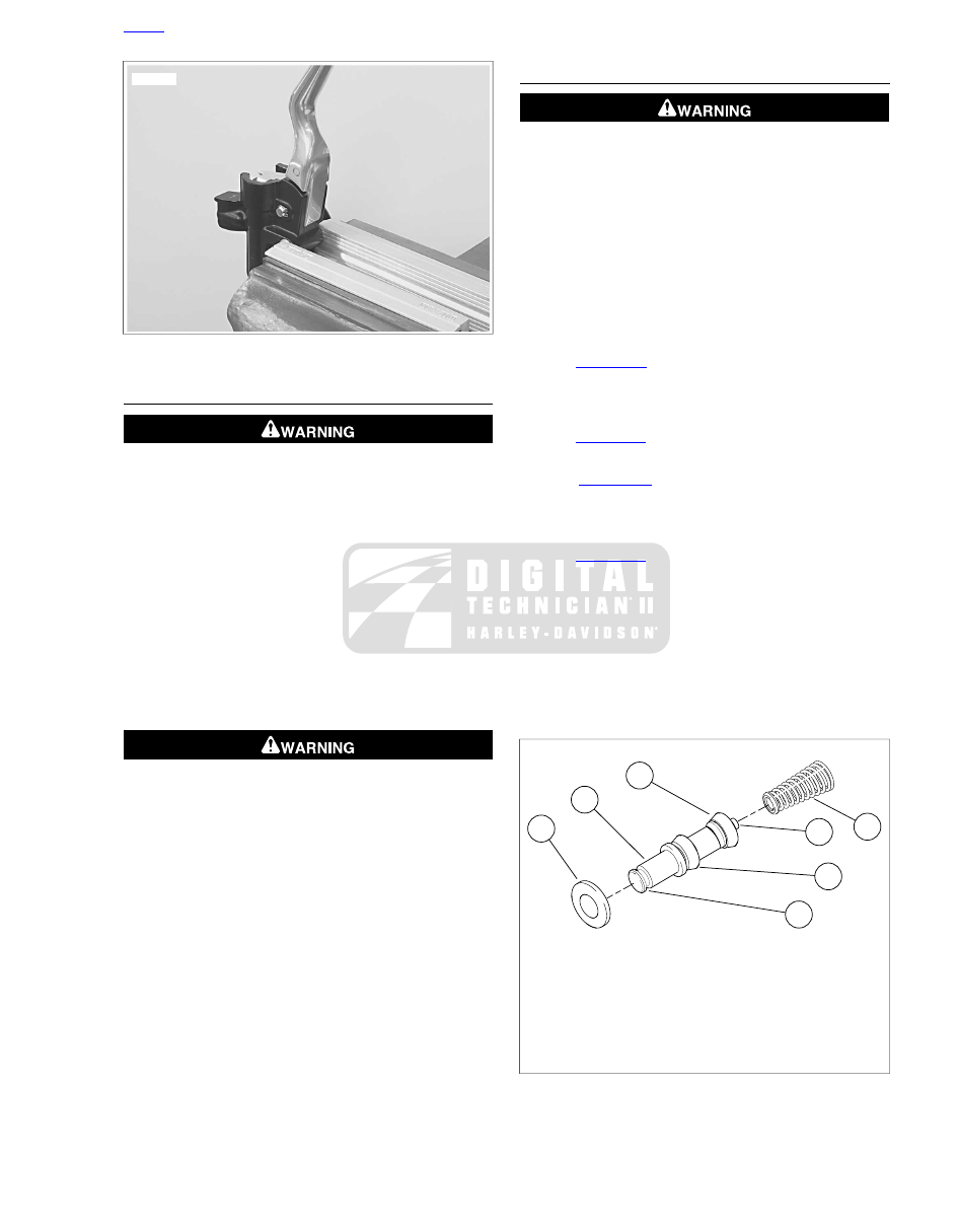
sm01241

Figure 2-54. Clamping Front Master Cylinder

CLEANING, INSPECTION AND REPAIR

Compressed air can pierce the skin and flying debris from
compressed air could cause serious eye injury. Wear
safety glasses when working with compressed air. Never
use your hand to check for air leaks or to determine air
flow rates. (00061a)

NOTE

Do not use a wire or similar instrument to clean drilled passages
in bottom of reservoir.

1.

Clean brake system components with denatured alcohol.
Do not contaminate with mineral oil or other solvents.

a.

Wipe dry with a clean, lint free cloth.

b.

Blow out drilled passages and piston bore with low
pressure compressed air from a clean air supply.

Use denatured alcohol to clean brake system components.
Do not use mineral-based solvents (such as gasoline or
paint thinner), which will deteriorate rubber parts even
after assembly. Deterioration of these components can
cause brake failure, which could result in death or serious
injury. (00291a)

2.

Carefully inspect all parts for wear or damage. Replace
as necessary.

a.

Inspect the piston bore in the master cylinder housing
for scoring, pitting or corrosion.

b.

Inspect the outlet port that mates with the brake line
banjo fitting. This is a critical sealing surface.

c.

Inspect diaphragm for damage.

ASSEMBLY

Do not use parts from single caliper repair kits (9/16 inch
bore) on dual caliper models. Likewise, do not use parts
from dual caliper repair kits (11/16 inch bore) on single
caliper models. Using incorrect parts can cause brake
failure, which could result in death or serious injury.
(00278a)

NOTES

Always reassemble the master cylinder using new parts
from the correct service repair kit.

CCI #20 BRAKE GREASE is recommended for lubrication
of cylinder bore, cups and seals prior to assembly.

See

Figure 2-54

Clamp front brake master cylinder in a

vise by the mirror mounting boss only. Use brass or alu-
minum jaw covers or other protective device on vise jaws
to prevent damage to master cylinder.

1.

See

Figure 2-54

Clamp master cylinder in a vise so that

banjo fitting hole is pointing straight down.

2.

See

Figure 2-53

Coat piston bore of master cylinder

housing (5), piston (14), primary cup (12) and secondary
cup (13) with CCI #20 BRAKE GREASE (21) supplied in
the service parts kit.

3.

See

Figure 2-55

. Install piston assembly into master cyl-

inder.

a.

Press small end of piston spring (4) onto mounting
boss (6) on piston (1).

b.

Slide piston/spring assembly, flared end of spring first,
into master cylinder bore so that spring seats against
counter bore (recess) at bottom of cylinder.

c.

Single disc piston:

Slide stop plate (7) down over

end of piston.

1

2

3

4

5

7

6

sm02406

1. Piston
2. Primary cup
3. Secondary cup
4. Piston spring
5. Dust boot groove
6. Piston spring mounting boss
7. Stop plate (single disc piston only)

Figure 2-55. Front Brake Master Cylinder Piston

(Typical-Single Disc Piston Shown)

HOME

2013 Sportster Service: Chassis 2-41

Wear safety glasses or goggles when removing or
installing retaining rings. Retaining rings can slip from the
pliers and could be propelled with enough force to cause
serious eye injury. (00312a)

NOTE

Use correct retaining ring pliers and correct tips. Verify that
tips are not excessively worn or damaged.

4.

See

Figure 2-53

.

a.

Dual disc master cylinder:

Press down on piston

(14) and install

new

retaining ring (15). Verify that

retaining ring is fully seated in groove.

b.

Single disc master cylinder:

Press down on piston

(14) and stop plate (22), and install

new

retaining ring

(15). Verify that retaining ring is fully seated in groove.

5.

Install

new

dust boot (16). Large lip of dust boot fits down

inside end of piston bore. Small lip of dust boot fits into
groove in end of piston (item 5,

Figure 2-55

).

6.

Apply approximately 0.1 g G40M BRAKE GREASE (from
service parts kit) to each of the following two locations:

a.

Pivot hole in brake hand lever (18).

b.

End of piston (14).

7.

Align hole in brake hand lever with hole in master cylinder
bracket. From top of assembly, slide pivot pin (9) through
bracket and hand lever.

Wear safety glasses or goggles when removing or
installing retaining rings. Retaining rings can slip from the
pliers and could be propelled with enough force to cause
serious eye injury. (00312a)

8.

Install

new

retaining ring (17) in pivot pin groove. Verify

that retaining ring is fully seated in groove.

9.

Remove master cylinder assembly from vise. Install cover
(2), diaphragm plate (3) and diaphragm (4) on master
cylinder reservoir. Install two screws (1) to fasten cover
to reservoir, but do not tighten at this time.

10. See

Figure 2-56

. Squeeze front brake lever and place a

5/32 in (4 mm) thick cardboard insert between brake lever
and lever bracket. Release brake lever.

sm01242

Figure 2-56. Install 5/32 in (4 mm) Cardboard Insert Before

Installing Master Cylinder Assembly

INSTALLATION

TORQUE VALUE

FASTENER

12.2-14.9 Nm

108-132

in-lbs

Brake master cylinder clamp,
front, screw

27.1-33.9 Nm

20-25 ft-lbs

Brake line banjo bolt

10.9-16.3 Nm

96-144

in-lbs

Mirror stem locknut

10.9-13.6 Nm

96-120

in-lbs

Cylinder head exhaust port nut

Do not remove or install the master cylinder assembly
without first positioning a 5/32-inch (4 mm) thick insert
between the brake lever and lever bracket. Removing or
installing the master cylinder assembly without the insert
in place may result in damage to the rubber boot and
plunger on the front stoplight switch. (00324a)

1.

See

Figure 2-57

. Position brake lever/master cylinder

assembly inboard of switch housing assembly (1). Engage
tab (5) on lower switch housing in slot (4) at top of brake
lever bracket (3).

2.

See

Figure 2-53

Align holes in handlebar clamp (8) with

master cylinder housing (5). Start two screws (6) with
washers (7). Beginning with top screw, tighten to 108-132

in-lbs

(12.2-14.9 Nm).

HOME

2-42 2013 Sportster Service: Chassis

5

4

3

2

1

sm01243

1. Switch housing assembly
2. 5/32 in (4 mm) cardboard insert
3. Brake lever bracket
4. Slot
5. Tab

Figure 2-57. Fitting Brake Lever/Master Cylinder To Right

Handlebar Switch Housing

Avoid leakage. Be sure gaskets, banjo bolt(s), brake line
and master cylinder bore are clean and undamaged before
assembly. (00322a)

NOTE

See

Figure 2-58

The master cylinder housing positive stops

for banjo fittings are different on XL Models and the XR 1200X.
Never intermix model components. When tightening the banjo
bolt, verify that the banjo fitting is correctly oriented and con-
tacts the positive stop.

3.

See

Figure 2-59

Position a

new

washer (8) on each side

of hydraulic brake line banjo fitting (6). Insert banjo bolt
(7) through washers and fitting. Thread bolt into master
cylinder housing. Tighten to 20-25 ft-lbs (27.1-33.9 Nm).

1

2

sm05497

1. XR 1200X
2. XL models

Figure 2-58. Front Brake Master Cylinder Identification

1

3

4

6

8

8

5

2

7

sm06942

1. Front brake master cylinder and reservoir
2. Mirror
3. Turn signal clamp screw
4. Locknut and washer
5. Turn signal assembly
6. Front brake banjo fitting
7. Banjo bolt
8. Sealing washer

Figure 2-59. Front Brake Master Cylinder (typical)

4.

See

Figure 2-53

. Position motorcycle so that top of master

cylinder reservoir is level. Remove two screws (1), front
master cylinder reservoir cover (2), diaphragm plate (3)
and diaphragm (4).

Direct contact of D.O.T. 4 brake fluid with eyes can cause
irritation. Avoid eye contact. In case of eye contact flush
with large amounts of water and get medical attention.
Swallowing large amounts of D.O.T. 4 brake fluid can cause
digestive discomfort. If swallowed, obtain medical atten-
tion. Use in well ventilated area. KEEP OUT OF REACH OF
CHILDREN. (00240a)

D.O.T. 4 brake fluid will damage painted and body panel
surfaces it comes in contact with. Always use caution and
protect surfaces from spills whenever brake work is per-
formed. Failure to comply can result in cosmetic damage.
(00239b)

NOTES

If DOT 4 brake fluid contacts painted surfaces, IMMEDI-
ATELY flush area with clear water.

Cover handlebar switches with a shop towel before adding
brake fluid to front master cylinder reservoir. Spilling brake
fluid on handlebar switches may render them inoperative.

See

Figure 2-60

Do not use sight glass (2) to determine

maximum fluid level. Sight glass should only be used as
a visual indicator that fluid level is low and needs attention.

HOME

2013 Sportster Service: Chassis 2-43

A ridge (1) is cast into the inside of the reservoir to help
determine the correct maximum fluid level.

Fill master cylinder only with DOT 4 BRAKE FLUID from
a sealed container.

Do not overfill reservoir. Do not reuse old brake fluid.

5.

See

Figure 2-60

. Add enough DOT 4 BRAKE FLUID to

reservoir to bring fluid level even with ridge (1) cast into
inside of reservoir, about 1/4 in (6.35 mm) below top edge.

1

2

sm01244

1. Cast-in ridge
2. Sight glass

Figure 2-60. Filling Front Master Cylinder Reservoir

A plugged or covered relief port can cause brake drag or
lock-up, which could lead to loss of control, resulting in
death or serious injury. (00288a)

6.

Verify proper operation of master cylinder relief port. Slowly
actuate brake hand lever with reservoir cover removed. A
slight spurt of fluid will break fluid surface in reservoir

compartment if all internal components are working prop-
erly.

7.

Bleed brake system. See

2.17 BLEEDING BRAKES

.

NOTE

On dual caliper models, bleed both calipers.

After repairing the brake system, test brakes at low speed.
If brakes are not operating properly, testing at high speeds
can cause loss of control, which could result in death or
serious injury. (00289a)

8.

See

Figure 2-59

. Install mirror (2), secure with locknut and

washer (4). Position mirror for rearward visibility. Tighten
locknut to 96-144

in-lbs

(10.9-16.3 Nm).

NOTE

XL 1200X: Install mirror upside down. Check clearance
between mirrors and gas tank while turning handlebar lock to
lock.

9.

All Models except XL 1200X:

Install turn signal assembly

(5). Position so lens faces directly forward. Verify turn
signal does not strike fuel tank when the handlebar is
turned full right. Tighten clamp screw (3) to 96-120

in-lbs

(10.9-13.6 Nm).

10. Verify operation of stop lamp.

After repairing the brake system, test brakes at low speed.
If brakes are not operating properly, testing at high speeds
can cause loss of control, which could result in death or
serious injury. (00289a)

11. Test brake system.

a.

Test ride motorcycle at low speed. If brake feels
spongy, repeat bleeding procedure.

b.

Test ride the motorcycle. If the brakes feel spongy,
bleed the system again. See

2.17 BLEEDING

BRAKES

.

HOME

2-44 2013 Sportster Service: Chassis

2.9

FRONT BRAKE CALIPER: XL MODELS

REMOVAL

NOTE

If only replacing brake pads, do not remove front brake cal-
iper(s). For brake pad replacement only, see

1.16 BRAKE

PADS AND DISCS: XL MODELS

.

Direct contact of D.O.T. 4 brake fluid with eyes can cause
irritation. Avoid eye contact. In case of eye contact flush
with large amounts of water and get medical attention.
Swallowing large amounts of D.O.T. 4 brake fluid can cause
digestive discomfort. If swallowed, obtain medical atten-
tion. Use in well ventilated area. KEEP OUT OF REACH OF
CHILDREN. (00240a)

NOTE

Damaged banjo bolt surfaces will leak when reassembled.
Prevent damage to seating surfaces by carefully removing
brake line components.

D.O.T. 4 brake fluid will damage painted and body panel
surfaces it comes in contact with. Always use caution and
protect surfaces from spills whenever brake work is per-
formed. Failure to comply can result in cosmetic damage.
(00239b)

NOTE

If DOT 4 brake fluid contacts painted surfaces, IMMEDIATELY
flush area with clear water.

1.

See

Figure 2-61

Remove bleeder nipple cap (9) from

bleeder valve (8) on front brake caliper (4).

2.

See

Figure 2-62

. Install end of a length of 5/16 in (7.9 mm)

ID clear plastic tubing over caliper bleeder valve, while
placing free end in a suitable container. Open bleeder
valve about 1/2 turn. Pump brake hand lever repeatedly
to drain brake fluid. Close bleeder valve.

NOTE

Dispose of brake fluid in accordance with local regulations.

3.

See

Figure 2-61

. Remove the banjo bolt (1) and both

washers (2) to detach front brake line (3) from caliper (4).
Discard washers.

4.

Remove pad pin plug (7).

5.

See

Figure 2-63

. Loosen, but do not remove, brake pad

pin.

6.

See

Figure 2-61

Remove both mounting bolts (6) (12

pt/10 mm). Pull caliper and mounting bracket assembly
rearward to disengage from brake disc.

9

8

3

1

7

4

5

6

2

sm01333

1. Banjo bolt
2. Washer (2)
3. Front brake line
4. Brake caliper
5. Caliper mounting bracket
6. Mounting bolt (2) (12 pt/10 mm)
7. Pad pin plug
8. Bleeder valve
9. Bleeder nipple cap

Figure 2-61. Front Caliper Assembly

sm01424

Figure 2-62. Bleeding Hydraulic System

HOME

2013 Sportster Service: Chassis 2-45

sm01334

Figure 2-63. Brake Pad Pin (Plug Removed)

DISASSEMBLY

1.

See

Figure 2-64

Remove brake pad pin (14) and brake

pads (8) from caliper body (15).

2.

Slide brake caliper off mounting bracket (1).

3.

Remove pad spring (16). Do not remove bleeder valve
(10) at this time.

4.

See

Figure 2-65

Install a discarded brake pad in the cal-

iper (1) with the backing plate (4) facing the pistons. Posi-
tion the brake pad so the friction material (3) is against
the back of the caliper, as shown.

5.

Loosely install brake pad pin (2) to hold brake pad in place.

Compressed air can pierce the skin and flying debris from
compressed air could cause serious eye injury. Wear
safety glasses when working with compressed air. Never
use your hand to check for air leaks or to determine air
flow rates. (00061a)

NOTE

Do not damage banjo bolt sealing surface or threads of banjo
bolt hole in brake caliper. Use an air nozzle with a rubber tip.

When removing piston with compressed air, piston can
develop considerable force and fly out of caliper bore.
Keep hands away from piston to avoid possible injury.
(00530b)

6.

See

Figure 2-66

Gently apply low pressure compressed

air to banjo bolt hole (3) to force pistons from caliper bores.

7.

Remove brake pad pin and brake pad.

8.

See

Figure 2-64

Remove both pistons (17) from caliper

bores by hand. If necessary, wiggle pistons gently to
completely remove.

NOTE

Damaged piston bores will leak when reassembled. Do not
use metal objects to remove or install objects from piston bores.
Prevent damage to pistons, seals and bores by only using a
wooden toothpick when servicing calipers.

9.

See

Figure 2-67

. Using a wooden toothpick (1), remove

dust seal (2) and piston seal (3) from each caliper bore.
Discard seals.

10. See

Figure 2-64

If necessary, remove bleeder valve (10).

HOME

2-46 2013 Sportster Service: Chassis

9

1

2

3

4

5

6

7

8

10

11

12

13

14

15

16

20

19

18

17

21

sm01812

12.

1.

Caliper bushing boot

Caliper bracket

2.

13.

Caliper pin boot

Pad pin plug

14.

3.

Pad pin

Screw (2)

4.

15.

Bolt pin (caliper)

Caliper body

16.

5.

Pad spring

Pad retainer (2)

6.

17.

Insulator (2)

Piston (2)

18.

7.

Piston seal (2)

Brake pad (2)

8.

19.

Brake pad set (includes item 9)

Dust seal (2)

20.

9.

Piston kit

Retainer clip (not sold separately)

10.

21.

Bleeder valve

Bolt pin (mounting bracket)

11. Bleeder nipple cap

Figure 2-64. Front Brake Caliper Assembly

HOME

2013 Sportster Service: Chassis 2-47

2

1

4

3

sm01335

1. Brake caliper
2. Brake pad pin
3. Brake pad friction material
4. Brake pad backing plate

Figure 2-65. Preparing Caliper for Piston Removal

2

1

3

4

sm01336

1. Low pressure air nozzle
2. Brake caliper
3. Banjo bolt hole
4. Brake pad

Figure 2-66. Removing Pistons

1

3

2

sm01337

1. Wooden toothpick
2. Dust seal
3. Piston seal

Figure 2-67. Caliper Seals

CLEANING, INSPECTION AND REPAIR

Use denatured alcohol to clean brake system components.
Do not use mineral-based solvents (such as gasoline or
paint thinner), which will deteriorate rubber parts even
after assembly. Deterioration of these components can
cause brake failure, which could result in death or serious
injury. (00291a)

1.

See

Figure 2-64

Wipe old lubrication from inside of caliper

pin boot (2) and caliper bushing boot (12) with a soft, clean
cloth.

2.

Clean all other rubber parts with DOT 4 BRAKE FLUID.
Do not contaminate with mineral oil or other solvents.
Clean all metal parts with denatured alcohol. Wipe parts
dry with a clean, lint-free cloth.

Compressed air can pierce the skin and flying debris from
compressed air could cause serious eye injury. Wear
safety glasses when working with compressed air. Never
use your hand to check for air leaks or to determine air
flow rates. (00061a)

3.

Blow out drilled passages and piston bore with low pres-
sure compressed air from a clean air supply. Do not use
a wire or similar instrument to clean drilled passages.

HOME

2-48 2013 Sportster Service: Chassis

4.

Carefully inspect all components. Replace any parts that
appear damaged or worn.

a.

Check pistons (17) for pitting, scratching or corrosion
on outside surfaces.

b.

Inspect caliper piston bores. Do not hone bores. If
bores show pitting or corrosion, replace caliper.

c.

Inspect pad pin (14) for grooving and wear. Measure
the pad pin diameter in an unworn area, and then in
the area of any grooving or wear. If wear is more than
0.011 in (0.28 mm), replace pad pin.

d.

Inspect caliper bolt pin (4). If damaged or excessively
worn, replace brake caliper assembly.

e.

Inspect caliper bushing boot and caliper pin boot. If
worn or damaged, replace.

f.

Always replace all seals after disassembly.

Always replace brake pads in complete sets for correct
and safe brake operation. Improper brake operation could
result in death or serious injury. (00111a)

5.

Inspect brake pads and brake disc. Replace if necessary.

a.

See

1.16 BRAKE PADS AND DISCS: XL MODELS

for specifications.

b.

See

2.5 WHEELS

for brake disc replacement pro-

cedure.

ASSEMBLY

TORQUE VALUE

FASTENER

4.0-6.9 Nm

35-61

in-lbs

Brake caliper bleeder valve

NOTE

Use ONLY KS62F assembly grease for lubrication. Use of DOT
4 BRAKE FLUID will result in increased brake lever travel.

1.

Lubricate the following parts prior to assembly using a
light coat of KS62F assembly grease from the service
parts kit. All other surfaces must be dry for assembly.

a.

Nose radius of pistons. See

Figure 2-68

.

b.

All surfaces of piston seals and dust seals.

NOTE

Damaged piston bores will leak when reassembled. Do not
use metal objects to remove or install objects in piston bores.
Prevent damage to bores by only using a wooden toothpick
when servicing calipers.

2.

See

Figure 2-67

. Install a

new

piston seal (3) and a

new

dust seal (2) into each piston bore.

3.

See

Figure 2-68

. Carefully insert pistons by hand, nose

radius first, into caliper bores. If installation shows resist-
ance, remove piston(s) and check that seals are properly
installed and fully seated in grooves.

4.

See

Figure 2-64

. Install bleeder valve (10) on caliper

housing if removed. Tighten bleeder valve to 35-61

in-lbs

(4.0-6.9 Nm).

5.

See

Figure 2-69

Install pad spring in channel. Press firmly

into place.

sm01338

Figure 2-68. Piston Nose Radius

sm01444

Figure 2-69. Front Caliper Pad Spring

LUBRICATING FRONT CALIPER BOLT PINS
AND BOOTS

1.

See

Figure 2-70

. Apply approximately 0.4 g of G40M

BRAKE GREASE inside caliper bushing boot (3) and cal-
iper pin boot (4).

2.

See

Figure 2-71

Apply G40M BRAKE GREASE inside

boot lip (8) to prevent sticking between boots (3, 4) and
bolt pins (5, 6).

3.

Assemble brake caliper and mounting bracket, carefully
sliding bolt pins into boots. Slide brake caliper all the way
onto mounting bracket until boot lips fit over tapered
shoulders (7) of bolt pins.

HOME

2013 Sportster Service: Chassis 2-49

3

1

5

4

2

6

sm01445

1. Front brake caliper
2. Caliper mounting bracket
3. Caliper bushing boot
4. Caliper pin boot
5. Caliper bolt pin
6. Bracket bolt pin

Figure 2-70. Lubricating Caliper Boots and Pins

1

7

5

4

8

2

1

3

6

2

4

5

sm01446

1. Front brake caliper
2. Caliper mounting bracket
3. Caliper bushing boot
4. Caliper pin boot
5. Caliper bolt pin
6. Bracket bolt pin
7. Tapered shoulder
8. Boot lip

Figure 2-71. Assembling Front Brake Caliper and Mounting

Bracket

INSTALLING BRAKE PADS IN CALIPER

TORQUE VALUE

FASTENER

14.8-19.6 Nm

131-173

in-lbs

Brake pad pin

2.0-2.9 Nm

18-25

in-lbs

Brake pad pin plug

NOTE

Rear brake pads cannot be used on front brake calipers.

1.

See

Figure 2-72

Insert one set of brake pads (1) into

caliper with friction material on pad facing opening for
brake disc. Curved portion of pad fits into recessed area
of caliper. Make sure brake pad front mounting tab (2) fits
into slot (5) in caliper mounting bracket (4).

2.

See

Figure 2-64

. Press brake pads (8) tightly up against

pad spring (16) and install pad pin (14). Tighten to 131-
173

in-lbs

(14.8-19.6 Nm).

NOTE

If pad pin does not fit, check the following:

You are using a set of pads, not two identical pads.

Pad spring orientation must match

Figure 2-69

.

See

Figure 2-72

Pad front mounting tabs (2) must be fully

seated in mounting bracket slot (5).

Pads must be pushed tight up against pad spring before
pad pin is installed.

3.

See

Figure 2-64

Install pad pin plug (13). Tighten to 18-25

in-lbs

(2.0-2.9 Nm).

3

1

3

5

4

2

2

1

sm01447

1. Brake pad
2. Front mounting tab
3. Pad pin hole
4. Front caliper mounting bracket
5. Slot

Figure 2-72. Front Brake Pads

HOME

2-50 2013 Sportster Service: Chassis

INSTALLATION

TORQUE VALUE

FASTENER

81-88 Nm

60-65 ft-lbs

Axle, front, nut

28.5-36.6 Nm

21-27 ft-lbs

Axle, front, pinch screw: XL
Models

38.0-51.6 Nm

28-38 ft-lbs

Brake caliper, front, mounting
bolt

27.1-33.9 Nm

20-25 ft-lbs

Brake line banjo bolt

1.0-2.0 Nm

9-17

in-lbs

Brake master cylinder, front,
reservoir cover screw

Direct contact of D.O.T. 4 brake fluid with eyes can cause
irritation. Avoid eye contact. In case of eye contact flush
with large amounts of water and get medical attention.
Swallowing large amounts of D.O.T. 4 brake fluid can cause
digestive discomfort. If swallowed, obtain medical atten-
tion. Use in well ventilated area. KEEP OUT OF REACH OF
CHILDREN. (00240a)

D.O.T. 4 brake fluid will damage painted and body panel
surfaces it comes in contact with. Always use caution and
protect surfaces from spills whenever brake work is per-
formed. Failure to comply can result in cosmetic damage.
(00239b)

NOTE

If DOT 4 brake fluid contacts painted surfaces, IMMEDIATELY
flush area with clear water.

1.

Dual Caliper Models:

Align calipers to brake discs.

a.

Tighten axle nut to 60-65 ft-lbs (81-88 Nm).

b.

Loosen axle pinch screw nut.

c.

Position right fork leg against bearing spacer. Tighten
axle pinch screw to 21-27 ft-lbs (28.5-36.6 Nm).

2.

See

Figure 2-73

. Place brake caliper (4) with mounting

bracket (5) over brake disc with bleeder valve (8) facing
upwards. Install mounting bolts (6) into mounting holes on
fork leg. Tighten to 28-38 ft-lbs (38.0-51.6 Nm).

Avoid leakage. Be sure gaskets, banjo bolt(s), brake line
and caliper bore are clean and undamaged before
assembly. (00321a)

NOTE

Brake caliper housing has a positive stop for banjo fitting. When
tightening banjo bolt into brake caliper in the next step, rotate
banjo fitting clockwise until it contacts positive stop.

3.

Position a

new

washer (2) on each side of hydraulic brake

line (3) banjo fitting. Insert banjo bolt (1) through washers
and fitting. Thread bolt into caliper housing. Tighten to 20-
25 ft-lbs (27.1-33.9 Nm).

4.

Dual Caliper Models:

Repeat previous two steps for other

brake caliper.

5.

Remove cover screws, top cover and gasket from front
brake master cylinder reservoir.

NOTES

See

Figure 2-74

. Do not use sight glass to determine

maximum fluid level. Sight glass should only be used as
a visual indicator that fluid level is low and needs attention.

Cover handlebar switches with a shop towel before adding
brake fluid to front master cylinder reservoir. Spilling brake
fluid on handlebar switches may render them inoperative.

Use only DOT 4 BRAKE FLUID from a sealed container.

Do not overfill reservoir. Do not reuse old brake fluid.

6.

See

Figure 2-74

Add enough DOT 4 BRAKE FLUID to

reservoir to bring fluid level even with ridge cast into inside
of reservoir, about 1/4 in (6.35 mm) below top edge.

After repairing the brake system, test brakes at low speed.
If brakes are not operating properly, testing at high speeds
can cause loss of control, which could result in death or
serious injury. (00289a)

7.

Bleed brake system. See

2.17 BLEEDING BRAKES

.

NOTE

On dual caliper models, bleed both calipers.

A plugged or covered relief port can cause brake drag or
lock-up, which could lead to loss of control, resulting in
death or serious injury. (00288a)

8.

Verify proper operation of master cylinder relief port. Turn
handlebar to level reservoir. Squeeze brake lever slowly
with reservoir cover removed. A slight spurt of fluid will
break the surface if all internal components are working
properly.

9.

See

Figure 2-74

Add enough DOT 4 BRAKE FLUID to

reservoir to bring fluid level even with ridge cast into inside
of reservoir, about 1/4 in (6.35 mm) below top edge.

10. Install gasket and cover on master cylinder with screws.

Tighten to 9-17

in-lbs

(1.0-2.0 Nm).

After repairing the brake system, test brakes at low speed.
If brakes are not operating properly, testing at high speeds
can cause loss of control, which could result in death or
serious injury. (00289a)

11. Test brake system.

a.

Turn ignition switch ON. Squeeze brake hand lever
to verify operation of the stop lamp.

b.

Test ride the motorcycle. If the brakes feel spongy,
bleed the system again. See

2.17 BLEEDING

BRAKES

.

HOME

2013 Sportster Service: Chassis 2-51

NOTE

Avoid making hard stops for the first 100 mi (160 km). This
allows the new pads to become conditioned to the brake discs.

9

8

3

1

7

4

5

6

2

sm01333

1. Banjo bolt
2. Washer (2)
3. Front brake line
4. Brake caliper
5. Caliper mounting bracket
6. Mounting bolt (2) (12 pt/10 mm)
7. Pad pin plug
8. Bleeder valve
9. Bleeder nipple cap

Figure 2-73. Front Caliper Assembly

1

2

sm01244

1. Cast-in ridge
2. Sight glass

Figure 2-74. Filling Front Master Cylinder Reservoir

HOME

2-52 2013 Sportster Service: Chassis

2.10

FRONT BRAKE CALIPER: XR 1200X

REMOVAL

NOTE

Do not remove front brake calipers if only replacing brake pads
See

1.17 BRAKE PADS AND DISCS: XR 1200X

.

Direct contact of D.O.T. 4 brake fluid with eyes can cause
irritation. Avoid eye contact. In case of eye contact flush
with large amounts of water and get medical attention.
Swallowing large amounts of D.O.T. 4 brake fluid can cause
digestive discomfort. If swallowed, obtain medical atten-
tion. Use in well ventilated area. KEEP OUT OF REACH OF
CHILDREN. (00240a)

NOTE

Damaged banjo bolt surfaces will leak when reassembled.
Prevent damage to seating surfaces by carefully removing
brake line components.

D.O.T. 4 brake fluid will damage painted and body panel
surfaces it comes in contact with. Always use caution and
protect surfaces from spills whenever brake work is per-
formed. Failure to comply can result in cosmetic damage.
(00239b)

NOTE

If DOT 4 brake fluid contacts painted surfaces, IMMEDIATELY
flush area with clear water.

1.

See

Figure 2-75

Remove bleeder nipple cap from bleeder

valve (1) on front brake caliper.

2.

See

Figure 2-76

. Install end of a length of 5/16 in (7.9 mm)

ID clear plastic tubing over caliper bleeder valve, while
placing free end in a suitable container. Open bleeder
valve about 1/2 turn. Pump brake hand lever repeatedly
to drain brake fluid. Close bleeder valve.

NOTE

Dispose of brake fluid in accordance with local regulations.

3.

See

Figure 2-75

Remove the banjo bolt (2) (metric) and

both washers (3) to detach front brake line from caliper.
Discard washers.

4.

Remove both mounting bolts (4) (metric). Pull caliper
assembly rearward to remove from brake disc.

1

3

2

4

5

sm06932

1. Bleeder valve
2. Banjo bolt (metric)
3. Sealing washer
4. Mounting bolt (metric)
5. Banjo fitting

Figure 2-75. Front Caliper Assembly: XR 1200X

sm01424

Figure 2-76. Bleeding Hydraulic System

HOME

2013 Sportster Service: Chassis 2-53

1

13

11

12

11

10

9

8

7

6

5

4

3

2

14

15

16

sm05107

9.

1.

Bleeder valve cap

Inner caliper housing

2.

10.

Upper piston (large) (2)

Caliper mounting bolt (2)

11.

3.

Bridge bolt (4)

Piston seal (large) (2)

4.

12.

Piston dust seal (large) (2)

Pad pin (2)

13.

5.

Pad set

Pad spring

6.

14.

Crossover seal

Piston dust seal (small) (2)

15.

7.

Piston seal (small) (2)

Outer caliper housing

8.

16.

Bleeder valve

Lower piston (small) (2)

Figure 2-77. Front Brake Caliper Assembly

DISASSEMBLY

1.

See

Figure 2-78

. Remove brake pad pins (1) and anti-

rattle spring (2).

2.

Slide one brake pad out of caliper assembly. Do not
remove bleeder valve (3) at this time.

3.

With one brake pad in the caliper, loosely install brake pad
pins (1) to hold brake pad in place.

Compressed air can pierce the skin and flying debris from
compressed air could cause serious eye injury. Wear
safety glasses when working with compressed air. Never
use your hand to check for air leaks or to determine air
flow rates. (00061a)

NOTE

Do not damage banjo bolt sealing surface or threads of banjo
bolt hole in brake caliper. Use an air nozzle with a rubber tip.

HOME

2-54 2013 Sportster Service: Chassis

When removing piston with compressed air, piston can
develop considerable force and fly out of caliper bore.
Keep hands away from piston to avoid possible injury.
(00530b)

4.

See

Figure 2-78

Gently apply low pressure compressed

air to banjo bolt hole (4) to force pistons from caliper bores.

5.

Remove brake pad pins and brake pad.

6.

Remove bridge bolts (5, 6) and separate caliper housings.

7.

Remove pistons from each housing by hand. If necessary,
wiggle pistons gently to completely remove.

NOTE

Damaged piston bores will leak when reassembled. Do not
use metal objects to remove or install objects from piston bores.
Prevent damage to pistons, seals and bores by only using a
wooden toothpick when servicing calipers.

8.

See

Figure 2-79

Using a wooden toothpick (1), remove

dust seal (2) and piston seal (3) from each caliper bore.
Discard seals.

9.

See

Figure 2-78

. If necessary, remove bleeder valve (3).

1

5

2

3

6

6

4

sm05099

1. Pad pins (2) (metric)
2. Spring
3. Bleeder valve
4. Banjo bolt hole
5. Bridge bolt, long (2)
6. Bridge bolt, short (2)

Figure 2-78. Preparing Caliper for Piston Removal

2

3

1

sm05100

1. Wooden toothpick
2. Dust seal
3. Piston seal

Figure 2-79. Caliper Seals

CLEANING, INSPECTION AND REPAIR

Use denatured alcohol to clean brake system components.
Do not use mineral-based solvents (such as gasoline or
paint thinner), which will deteriorate rubber parts even
after assembly. Deterioration of these components can
cause brake failure, which could result in death or serious
injury. (00291a)

1.

Clean all rubber parts with DOT 4 BRAKE FLUID. Do not
contaminate with mineral oil or other solvents. Clean all
metal parts with denatured alcohol. Wipe parts dry with a
clean, lint-free cloth.

Compressed air can pierce the skin and flying debris from
compressed air could cause serious eye injury. Wear
safety glasses when working with compressed air. Never
use your hand to check for air leaks or to determine air
flow rates. (00061a)

2.

Blow out drilled passages and piston bore with low pres-
sure compressed air from a clean air supply. Do not use
a wire or similar instrument to clean drilled passages.

3.

Carefully inspect all components. Replace as necessary.

a.

Check pistons for pitting, scratches or corrosion on
outside surfaces.

b.

Inspect piston bores. Do not hone bores. Replace as
necessary.

NOTE

The pad pins are manufactured with a relief near the center
of their length, where the pad spring touches. Do not use

HOME

2013 Sportster Service: Chassis 2-55

this area as a measurement point to determine pad pin
wear.

c.

Inspect pad pin for grooving and wear at the pad
contact points. Measure the pad pin diameter in an
unworn area and in an area of any grooving or wear.
If wear exceeds 0.011 in (0.28 mm), replace pad pin.

d.

Inspect pad spring for wear or cracks. Replace if
necessary.

e.

Always replace all seals after disassembly.

Always replace brake pads in complete sets for correct
and safe brake operation. Improper brake operation could
result in death or serious injury. (00111a)

4.

Inspect brake pads and brake disc. Replace if necessary.

a.

Specifications:

See

1.17 BRAKE PADS AND DISCS:

XR 1200X

.

b.

Brake Disc:

See

2.5 WHEELS

.

ASSEMBLY

TORQUE VALUE

FASTENER

16.9-24.5 Nm

12-18 ft-lbs

Brake caliper, front, bridge bolt

14.8-19.6 Nm

131-173

in-lbs

Brake pad pin

4.0-6.9 Nm

35-61

in-lbs

Brake caliper bleeder valve

1.

Lubricate the following parts using a light coat of G40M
BRAKE GREASE. All other surfaces must be dry.

a.

Nose radius of pistons.

b.

All surfaces of piston seals and dust seals.

NOTES

Damaged piston bores will leak when reassembled. Do
not use metal objects to remove or install objects in piston
bores. Prevent damage to bores by only using a wooden
toothpick when servicing calipers.

Pistons and bores differ slightly in diameter: one large and
one small in each housing.

2.

See

Figure 2-79

. Install a

new

piston seal (3) and a

new

dust seal (2) into each piston bore.

3.

See

Figure 2-80

Carefully insert pistons (2, 3) by hand,

nose radius first, into caliper bores. If installation shows
resistance, remove piston(s) and check that seals are
properly installed and fully seated in grooves. Press pis-
tons completely into bores.

4.

Install

new

crossover seal (1).

5.

See

Figure 2-78

. Install bridge bolts (5, 6).

a.

Apply a drop of LOCTITE 569 THREAD SEALANT
to the threads of the bridge bolts.

b.

Assemble caliper housings and secure with bridge
bolts. Verify the bridge bolts are in the correct loca-
tions based on length.

c.

Tighten bridge bolts to 12-18 ft-lbs (16.9-24.5 Nm).

6.

See

Figure 2-81

. Install brake pads and pad spring. Verify

the spring is oriented as shown with the arrow and word
"UP" (2) facing the banjo bolt hole (1). Secure with pad
pins (3).

7.

Tighten pad pins to 131-173

in-lbs

(14.8-19.6 Nm).

8.

Install bleeder valve on caliper housing if removed. Tighten
bleeder valve to 35-61

in-lbs

(4.0-6.9 Nm).

1

2

3

sm05102

1. Crossover seal
2. Large piston (2)
3. Small piston (2)

Figure 2-80. Caliper Housings and Pistons

1

3

2

sm05101

1. Banjo bolt hole
2. Arrow and word "UP"
3. Pad pins (2)

Figure 2-81. Front Caliper Pad Spring Orientation

HOME

2-56 2013 Sportster Service: Chassis


Content      ..     12      13      14      15     ..