Harley Davidson 2011 Touring Models. Electrical Diagnostic Manual - page 27
 

  Главная      Harley Davidson     Harley Davidson 2011 Touring Models. Electrical Diagnostic Manual


Search            copyright infringement  


Content      ..     25      26      27      28     ..


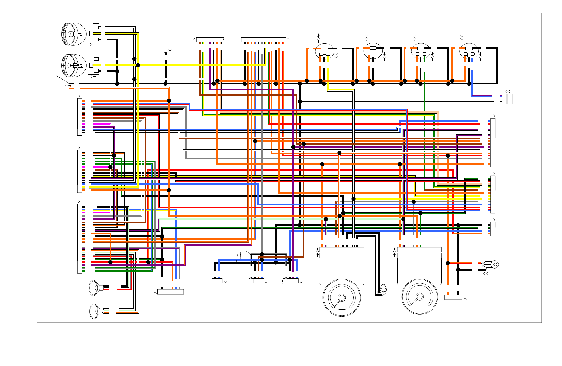
Harley Davidson 2011 Touring Models. Electrical Diagnostic Manual - page 27


[29B]

(BK)

HDI Only

Cigar

Lighter

Tachometer

Speedometer

See

Front Lighting,

Console Harness,

ABS

See

Front Lighting,

Console Harness,

ABS

See

Front Lighting,

Console Harness,

ABS

LH Front

Turn Signal

RH Front

Turn Signal

Front Fender

Tip Lamp

Trip Odometer

Reset Switch

(GY)

[34B]

[35B]

2

1

2

1

3

S

+

2

1

2

1

3

S

+

2

1

2

1

3

S

+

2

1

2

1

3

S

+

1

2

3

4

5

6

7

8

9

10

11

12

1
2
3
4
5
6
7
8
9

10
11
12

1

2

3

4

5

6

7

8

9

10

11

12

1 2 3 4 5 6 7

1
2
3
4
5
6
7
8
9

10
11
12
13

15
16
17
18
19
20
21
22
23

1

2

3

RPM x 100

1 2

5 6 7

1 2

5 6 7

Ignition

Ser

ia

l

D

at

a

B

a

tte

ry

Accesso

ry

Ground

1 2

5

8

9 11

6 7

1 2

5

8

9 11

6 7

Ignition

Ser

ia

l

D

at

a

B

a

tte

ry

Accesso

ry

Ground

T

rip

Odometer-

Reset

Switch

Fue

l

Le

v

el

T

ri

p

Ss

witch

A

B

C

D

1

3

4

5

6

7

8

9

10

11

1

2

3

4

5

6

7

8

9

10

11

12

(BK)

1
2
3

1
2
3

TEMP Signal
Ground

1

2

3

1

2

Air

Temperature

Air

Temperature

Sensor

4

1

2

3

4

6

Oil

Pressure

See

Classic/Ultra

Radio Circuit

Right Front

Speaker

Left Front

Speaker

FLTRX

Only

Headlamp 2

Ground

To Upper

Triple Clamp

Fairing Harness

See Indicators,

Fairing Switches,

Handlebar Switches

Fairing Harness

See Indicators,

Fairing Switches,

Handlebar Switches

See Main

Harness

(1 Or 2 Of 5)

See Main

Harness

(1 Or 2 Of 5)

See Main

Harness

(1 Or 2 Of 5)

Audio Harness

See

Classic/Ultra

Radio Circuit

On All Except FLTRX

Headlamp

Hi Beam

Lo Beam

GND

[38A]

[38A-2 ]

2

1

3

2

1

3

13

14

15

16

13

14

Fuel

Voltmeter

(BK)

Hi Beam

Lo Beam

GND

[154A]

LGN/BK

LGN/BK

GY/BK

BN/GN

BN/GN

GY/BK

GY/BK

BE/BK

BN/BK

LGN/V

LGN/V

LGN/V

LGN/V

LGN/W

LGN/W

BN/BK

BK/GN

BK/GN

BK/GN

BK/GN

BK/GN

BN/GY

BN/GY

BK/GN

BK/GN

BK/GN

GY/GN

GN/BE

GY/GN

GN/BE

BN/O

BN/O

O/BE

O/BE

V/GY

V/GY

GN/Y

GN/Y

R/GN

R/GN

BE/V

BE/V

BN

BK

BK

BK

BK

BK

BK

BK

TN

TN

BK

BK

BK

V/O

O/W

O/W

O/R

O/R

O/R

Y

W

Y

Y

W

W

Y

W

V

V

O

O

O

O

O

O

BK

BK

BK

BK

BK

BK

BK

O

O

O

BK/R

W/BN

GY/W

GY/W

GY/R

GY/R

PK/W

PK/W

PK/W

BK/R
Y/BK

BE/Y

BE/Y

V/BK

V/BK

V/BK

O/BK

O/BK

W/BE

BN/W

BN/W

W/BK

R/BE

R/BE

GY

BE

BE

BE

BE

BE

BE

BN

BN

BK

BK

BK

BK

BK

O/R

BK

BK

BK

O/W

BE/BK

BK/R

BK/R

W/BE

W/BN

W/BK

GY

O/W

O/W

O/W

W/O

W/O

R/O

V/O

R/O

BN/GY

O/BE

R/O

R/O

W/V

V

Y/BK

O/W

W/V

Y/W

Y/W

Y/W

O

O

O

O

O

[108B]

[108A]

(BK)

[39B]

[39A]

[115A]

[115B]

[113A]

[113B]

[111A]

[111B]

[117A]

[117B]

[114A]

[114B]

[112A]

[112B]

[110A]

[110B]

[116A]

[116B]

[107A]

[107B]

[15A]

[2A]

[1A]

[6B]

[21A]

[105A]

[32A]

Heated Grips

(

If Equipped

)

2

1

[189B]

[31RA]

[31LA]

[GND 3]

[132A]

[132B]

[22B]

[24B]

[27B]

[38B-2]

[38B]

Left Hand Controls

See Indicators,

Fairing Switches,

Handlebar Switches

Right Hand Controls

See Indicators,

Fairing Switches,

Handlebar Switches

et00389

Figure B-19. Fairing Harness: 2011 Touring

See Fairing Harness

See Main Harness

(3 Or 4 of 5)

See Main Harness

(3 Or 4 of 5)

See Main Harness

(3 Or 4 of 5)

See Main Harness

(3 Or 4 of 5)

Radio Function Switch

Right Turn Switch

Engine Stop Switch

Start Switch
Cruise Set/Resume Switch

(Ultra Models Only)

PTT & SQ (Push To Talk & Squelch)

(Ultra Models Only)

Horn Switch

Headlamp Hi/Lo Switch

Left Turn Switch

Radio Audio Control

2
3
4
5
6

1

2

3

4

5

6

7

8

9

10

11

12

Left Hand

Controls

7
8
9

10
11
12

Right Hand

Controls

Front Stop

Lamp Switch

1

13

14

ACC

CRUISE

SPKR

SPOT

Fairing Harness

See Fairing Harness

1

2

3

4

5

6

7

8

9

10

11

12

1 2 3 4

1 2 3 4

Connectors

On FLT

Models

Only

Clutch Lockout Switch

Right

Turn

Oil

Pressure

Neutral

High

Beam

Left

Turn

Indicator

Lamps

(BK)

1 2 3 4 5 6 7

BK

BK

BK

BK

O/R

O/V

O/V

V/O

V/O

V/O

V/O

O

O/R

O

Y

Y

GY/BK

GY/BK

BK/GN

BK/GN

BK/GN

BK/GN

R/GN

R/GN

O/BE

O/BE

O/BE

O/BE

BN/O

BN/O

BK/GN

BN/O

BN/O

BN

BN

BK

TN

BK

BK

BK

TN

O

O

W

W

Y

W

V

O

V

GN/Y

GN/Y

GY

BK

BE

O/W

R/Y

W/V

O/W

BE/BK

GY/GN

GN/BE

BN/BK

V/BK

PK/W

BK/R

O/BK

Y/BK

W/BK
W/BN

BK/R

GY/W

V/BK

BN/W

PK/W

W/BE

[105D]

[105C]

[105B]

[21B]

[24A]

[22A]

Fairing Harness

See Fairing Harness

See Fairing Harness

Except

FLHR/C

Right Hand

Controls

Right Turn Switch

Cruise Set/Resume Switch

(FLHRC Only)

Front Stop

Lamp Switch

1
2
3
4
5
6

1

2

(BK)

(BK)

(BK)

(GY)

(FLHRC Only)

Engine Stop Switch
Start Switch

BE/BK

W/BK

W/BN

W/BE

BK/R

GY

O/W

R/Y

[22A]

[159A]

FLHR/C

Except

FLHR/C

(GY)

Left Hand

Controls

Left Turn Switch

1
2
3
4

5

6

7
8

Clutch

Lockout Switch

Cruise On/Off Switch

(FLHRC Only)

2

(FLHRC Only)

(GY)

Horn Switch
Lights Hi/Low Switch

Y/BK

R/GN

BK/R

BE

BK

O/W

W/V

W

Y

[24A]

[158A]

Except

FLHR/C

et00390

Figure B-20. Indicators, Fairing Switches, Handlebar Switches: 2011 Touring

Figure B-20.

Figure B-20.

Indicators, Fairing Switches, Handlebar Switches: 2011

Touring

Indicators, Fairing Switches, Handlebar Switches: 2011

Touring

69

69

72

72

1

2
3
4
9

10
12

1

2
3
4
9

10
12

TSM/TSSM

ECM

Right Hand

Controls

Engine Stop Switch

Start Switch

3
4

6

Left Hand

Controls

FLHR/C

Except FLHR/C

Clutch Lockout

Switch

3
4

6

Starter

Left

GND 1

Dirty

Right

GND 2

Clean

Main Fuse

40A

B

A

Red

Band

(BK)

Left GND 1

Dirty

B

A

Neutral

5 6

5

Battery

Battery

Ignition

Serial Data

Neutral Switch

Start Relay Control

Serial Data

Engine Stop Switch

Clutch Lockout Switch

Ground

BK

BK/R

[64-2B]

[64-1B]

Neutral

Switch

[21A]
[21B]

[5B]

[128B]

[128A]

[24B]

[24A]

[30B]

[30A]

Start

Relay

Lighting

Relay

Battery 15A

Ignition 15A

C

B

A

C

B

A

Ignition

Switch

12 12

7

7

BK

8

8

7

7

BK

[24B]

[24A]

FLHR/C

FLHR/C

Except

FLHR/C

Except

FLHR/C

13 13

FLHR/C

Except

FLHR/C

(Gray)

10

10

2

11

12

2

11

12

3

6

3

6

[209A]

[209B]

HFSM

(Black)

1
2
3

1
2

1
2

3

Receive Antenna

Xmit Antenna A

Xmit Antenna B

Xmit Antenna A

Xmit Antenna B

BK

Y/BK
O/Y

BK

O/Y

Ignition

Switch

85

86

30

87

2

1

3

5

4H

3G

3H

4G

85

86

30

87

2

1

3

5

2J

1G

1J

2G

BK/GN

BN/GY

TN/GN

BK

BK

BK

BK

GN

BK

TN

BK

R/GY

R/BK

R/GY

R/BK

R

R

R/GY

R/BK

R

R/GY

R/BK

R/BK

BK/R

R/GY

R/BK

R

R

R

R

GN

BK

GY

GY

BK/GN

BK/GN

BK/GN

BK/GN

BK/R

BK/R

BK/R

BK/R

BK/R

BK/GN

BK/GN

BK/GN

BK/R

BK/R

BK/R

BK/R

BK/R

BK/R

BK/R

BK/R

TN

LGN/V

LGN/V

BN/GY

BK/GN

W/BK

W/BK

W/BK

BK/R

W/BK

GY

TN

GY

W/BK

W/BK

BK/R

GY

GY

W/BK

BK/R

GY

GY

GY

W/BK

GY

TN

TN

BK/GN

BK/R

BK/R

TN

TN

TN

TN

R

R

R

TN

TN

O

(BK)

Neutral

7 6

7

[21A]
[21B]

TN

R

TN

O

[33A]

[33B]

[33A]

[33B]

[222A]

[222B]

2D

2C

1F

1E

[131]

[2B]

[2A]

[1B]

[1A]

[20B]

[20A]

B+

IGN

ACC

OFF

IGN

A

C

B

ACC

B+

IGN

ACC

OFF

IGN

3

1

2

ACC

[208B]

[208A]

[78B]

[78A]

[22B]

[22A]

Start Relay Enable

Start Relay Input

C

C

D

D

(Except

Anti-Theft

Tracking

Module)

(Anti-Theft

Tracking

Module)

C

C

Anti-Theft

Tracking

Module

TN/GN

TN/GN

TN/GN

TN/GN

TN/GN

GN

GN

[267B]

[267A]

[266A]

[266B]

et00391

Figure B-21. Starting Circuit: 2011 Touring

2.

Is voltage greater than 5.25V?

a.

Yes. Repair short to voltage on (BN/O) wire.

b.

No.

Go to Test 9.

9. Ground Circuit Open Test

1.

Connect TCA [211].

2.

Clear DTCs using odometer self-diagnostics. See

2.1 INITIAL DIAGNOSTICS, Odometer Self-Diagnostics

.

3.

Start the vehicle and operate the throttle.

4.

Did the DTC return?

a.

Yes. Replace the TCA. See the service manual.

b.

No. Operation normal.

DTC P2138

TOOL NAME

PART NUMBER

HARNESS CONNECTOR TEST KIT

HD-41404-C

BREAKOUT BOX

HD-48637

Table 6-99. DTC P2138 Diagnostic Faults

POSSIBLE CAUSES

Open in TGS-1 circuit

Short to ground in TGS-1 circuit

Short to voltage in TGS-1 circuit

Open in TGS-2 circuit

Short to ground in TGS-1 circuit

Short to voltage in TGS-1 circuit

TCA malfunction

1. TGS-2 Voltage Test

1.

Connect BREAKOUT BOX (Part No. HD-48637) between
wire harness [78B] and ECM [78A] leaving [78A] discon-
nected. See 

1.2 DIAGNOSTIC TOOLS

2.

Disconnect TCA [211].

3.

Disconnect TGS [204].

4.

Using HARNESS CONNECTOR TEST KIT (Part No. HD-
41404-C) and a multimeter, test for continuity between
breakout box terminal 59 and [204B] terminal 5.

5.

Is continuity present?

a.

Yes.

Go to Test 2.

b.

No. Repair open in (BE/GN) wire.

2. TGS-2 Circuit Test

1.

Test for continuity between breakout box terminal 59 and
61.

2.

Is continuity present?

a.

Yes. Repair short to ground in (BE/GN) wire.

b.

No.

Go to Test 3.

3. Sensor Power Circuit Test

1.

Test for continuity between breakout box terminal 59 and
50.

2.

Is continuity present?

a.

Yes. Repair short between (BE/GN) and (BN/O) wires.

b.

No.

Go to Test 4.

4. Sensor Ground Test

1.

Using HARNESS CONNECTOR TEST KIT (Part No. HD-
41404-C) and a multimeter, test for continuity between
breakout box terminal 39 and TGS [204B] terminal 4.

2.

Is continuity present?

a.

Yes.

Go to Test 5.

b.

No. Repair open in (V/Y) wire.

5. Shorted 5V Circuit Test

1.

Test for continuity between breakout box terminals 39 and
61.

2.

Is continuity present?

a.

Yes. Repair short to ground in (V/Y) wire.

b.

No.

Go to Test 6.

6. Sensor Ground Circuit Test

1.

Test for continuity between breakout box terminals 39 and
50.

2.

Is continuity present?

a.

Yes. Repair short between (V/Y) and (BN/O) wires.

b.

No.

Go to Test 7.

7. Sensor Ground-2 Open Circuit Test

1.

Test for continuity between breakout box terminal 62 and
[204B] terminal 1.

2.

Is continuity present?

a.

Yes.

Go to Test 8.

b.

No. Repair open in (BK/GY) wire.

8. TGS-2 Circuit Test

1.

Turn IGN ON.

2.

Measure voltage between breakout box terminals 39 and
61.

3.

Is voltage greater than 5.25V?

a.

Yes. Repair short to voltage on (V/Y) wire.

b.

No.

Go to Test 9.

9. Sensor Ground Continuity Test

1.

Measure voltage between breakout box terminals 59 and
61.

2.

Is voltage greater than 5.25V?

a.

Yes. Repair short to voltage on (BE/GN) wire.

b.

No.

Go to Test 10.

HOME

6-96  2011 Touring Diagnostics:  Engine Management

10. Ground Circuit Open Test

1.

Connect [204].

2.

Clear DTCs using odometer self-diagnostics. See

2.1 INITIAL DIAGNOSTICS, Odometer Self-Diagnostics

.

3.

Start the vehicle and operate the throttle.

4.

Did the DTC return?

a.

Yes. Replace the TCA. See the service manual.

b.

No. Operation normal.

HOME

2011 Touring Diagnostics:  Engine Management  6-97

6.32

DTC P2176

DESCRIPTION AND OPERATION

The TAC system sets DTC P2176 when the ECM determines
the zero position of the throttle plate has not been successfully
learned.

At power up, the ECM adjusts the throttle plate to the limp-
home position, then begins to move the throttle plate closed.
The ECM monitors and verifies the amount of movement that
occurred. The throttle plate minimum position is held briefly
then verified against the expected minimum and maximum
range of throttle. If the zero position is found within range, then
the position is stored.

If the ECM is not able to learn the minimum position or if the
learning fails four consecutive ignition cycles, the ECM initiates
DTC P2176. Refer to 

Table 6-100

.

Table 6-100. Code Description

DESCRIPTION

DTC

TCA close position not learned

P2176

DTC P2176

Table 6-101. DTC P2176 Diagnostic Faults

POSSIBLE CAUSES

Induction module malfunction

Mechanical interference

1. Air Inlet Interference Test

1.

Inspect the air inlet and check for foreign debris and/or
mechanical interference to the throttle plate.

2.

Were any issues found?

a.

Yes.

Go to Test 2.

b.

No.  Replace the induction module. See the service
manual.

2. Validation Test

1.

Remove obstructions and foreign debris from inlet and
check throttle plate movement.

2.

Clear DTCs using odometer self-diagnostics. See

2.1 INITIAL DIAGNOSTICS, Odometer Self-Diagnostics

.

3.

Start the engine and operate the throttle.

4.

Check for DTCs. See 

2.1 INITIAL DIAGNOSTICS, Odo-

meter Self-Diagnostics

.

5.

Did DTC P2176 set?

a.

Yes. Replace the induction module. See the service
manual.

b.

No.  Repair complete.

HOME

6-98  2011 Touring Diagnostics:  Engine Management

[13B]

[13A]

[78B]

[78A]

Y/GN

R

V/O

W/Y

V/Y

R/W

V/W

GN/GY

BK/PK

PK/GN

BE/GN

BK/GY

BK/GN

BK/BN

LGN/Y

GN/W

GY/BE

BN/R

BK

BN/V

BK/W

BK/Y

PK/O

BN/O

PK/Y

Y/GN

Y/BE

BE/O

PK/O

V/BE

BK/Y

BN/O

Y/GN

O/GY

O/GY

BN/O

BK/W

PK/Y

BK/W

Y/BE

BE/O

Y/GN

Y/GN

Y/GN

W/Y

V/BE

BK/O

GY/Y

V/GY

V/GY

W/GN

W/GN

BK

GY

BE

BN

V/W

R/W

R

R

V

LGN/Y

BK/GY

BE/GN

BK/GY

R/W

V/Y

1
2
3
4

A

A

B

A

B

A

B

A

B

B
C
D

A

Power

Ion Sense

Coil Rear

Coil Front

B
C
D

TGS

CKP

Sensor

ET

Sensor

TCA

TMAP

Sensor

Ignition Coil

VSS

Rear Fuel

Injector

Front Fuel

Injector

System

Relay

1

6

5

4

3

2

1

1

2

1

2

6 5 4 3 2 1

6 5 4 3 2 1

6 5 4 3 2 1

6 5 4 3 2 1

1

A

B

C

A

B

C

2

A B

A B

3 4

1 2

Front ACR

(If Equipped)

2 1

2 1

3 4

6

5

4

3

2

1

B

D

B

D

4

1

Fuel Tank

Harness

Fuel Pump

Assembly In Tank

4

Fuel

Pump

Fuse

15A

To 15A

ECM Fuse

To 15A

Exhaust

Control Fuse

Rear

HO2S

(BK)

Front

HO2S

Active

Exhaust

(HDI Only)

BK

V/O

BK

PK/GN

BK/BN

BK/BN

GN/GY

BK

LGN/R

Right

GND 2

Y/GN

Y/GN

V/GY

V/GY

Y/GN

Y/GN

GY/Y

Purge Solenoid

(Optional)

A

B

A

B

BE/GY

[79A]
[79B]

[224A]

[224B]

[204A]

[204B]

[90A]

[90B]

[203AF]

[203BF]

Rear ACR

(If Equipped)

2 1

2 1

[211A]
[211B]

[20A]
[20B]

[80A]

[80B]

[141A]

[141B]

[141B]

[65A]

[65B]

[179B]

ECM

Exhaust

Actuator

Rear

Fuel

Injector

TMAP

Sensor

Input

F

ront

Fuel

Injector

Throttle

Actuator

Control

HI

Throttle

Actuator

Control

LO

O2

Heater

Ground

TPS

2

TPS

1

Exhaust

F

eedbac

k

TGS

2

V

ehicle

Speed

Input

CKP

Sensor

Rear

HO2

Sensor

IA

T

Sensor

5V

Sensor

P

o

w

er

1

ET

Sensor

12V

P

o

w

er

Rear

Ignition

Coil

F

ront

Ignition

Coil

TGS

1

5V

Sensor

Ground

1

5V

Sensor

Ground

2

CKP

Sensor

(+)

V

ehicle

Speed

Ground

F

ront

HO2

Sensor

5V

Sensor

P

o

w

er

2

Ground

21

Purge

Solenoid

20

23 24

28 29 30 31

363738 39 4043 46

4950 51 52 53 54

59 61 62 63 64

66

68 73

HO2S

Retur

n

48

4

3
2
1

4

3
2
1

GY/BE

Ion

Sense

33

21

20

A

CR

Ground

19

19

23 24

28 29 30 31

363738 39 4043 46

4950 51 52 53 54

59 61 62 63 64

66

68 73

48

33

GN/W

GN/W

Y/GN

Y/GN

O/GY

14

B

D

15

BK

14

15

85

86

30

87

3

5

3D

4C

O/GY

BK

O/GY

BK

FLHR/C

EXCEPT

FLHR/C

BK

BK/W

BK/O

BN/R

BN/O

BN/V

BK/PK

4A

4B

[84B]

[84A]

[85B]

[85A]

[95B]

[95A]

[83B]

[83A]

[138A]

[137A]

[203AR]

[203BR]

em00702

Figure 6-45. EFI Simplified Schematic

HOME

6-100  2011 Touring Diagnostics:  Engine Management

6.34

NO ECM POWER

DESCRIPTION AND OPERATION

Constant power is supplied to the ECM through terminal 71.
The ECM turns on when power is applied to terminal 72 of
connector [78]. The ECM goes through an initialization
sequence every time power is removed and re-applied to ter-
minal 72. The only visible part of this sequence is the check
engine lamp. Upon starting, the check engine lamp will illu-

minate for 4 seconds and then (if parameters are normal) go
out.

If battery power is absent at ECM terminal 71:

DTCs cannot be cleared. Tool will show them as cleared
but will be present next time ignition key is cycled.

ECM cannot be re-flashed.

4

6

7

5

9

3

8

1

2

ed01820

1.

Tail light connector [7]: except FLHX, FLTRX

2.

Console pod [53]

3.

Positive battery terminal

4.

Hands-free antenna connector [209]

5.

Fuel pump subharness connector [13]

6.

Purge solenoid [95]

7.

P&A accessory connector [4]

8.

Negative battery terminal

9.

ECM [78]

Figure 6-46. Electrical Connectors Under Seat

Connector Information

For additional information about the connectors in the following
diagram(s) and diagnostic procedure(s), including the color of
the harness test kit terminal probes, see 

B.1 CONNECTORS

.

HOME

6-102  2011 Touring Diagnostics:  Engine Management

TSM/

TSSM/

HFSM

ECM

Main Fuse

40A

Battery

Ignition

Switch

[33A]

ECM
Fuse

To

System

Relay

Ignition

Fuse

15A

2

B A

3

Engine Stop

Switch

Ground

73

73

Engine Stop Switch

72

72

12V Battery

71

71

Ignition

2

2

3 4

3 4

GY

GY

GY

GY

BE/GY

BE/GY

R/BK

BK/GN

BE/GY

W/BK

W/BK

W/BK

W/BK

GY

W/BK

BK

6

3

6

3

15A

R

R

R

R

[5B]

[33B]

[78B]

[78A]

[30B]

[30A]

[22B]

[22A]

[1B]

[1A]

FLHX, FLHTC/CU, FLTR

FLHR/C

GY

W/BK

GY

W/BK

FLHX,

FLHTC/CU,

FLTR

FLHR/C

[222A]

[222B]

[33B]

B
A

R/BK

R

R/BK

R

R/BK

R

R/BK

R

2F

2E

1F

1E

B
A

B
A

em00820

Figure 6-47. ECM Power Circuit

NO ECM POWER

TOOL NAME

PART NUMBER

BREAKOUT BOX

HD-48637

Table 6-103. No ECM Power Diagnostic Faults

POSSIBLE CAUSES

ECM malfunction

Electrical system malfunction

Open or short to ground in ECM battery circuit

Open in ignition circuit

Engine stop switch malfunction

1. ECM Fuse Test

1.

Check ECM fuse.

2.

Is fuse good?

a.

Yes.

Go to Test 2.

b.

No. Repair short to ground on (BE/GY) wire and
replace fuse.

2. IGN Fuse Test

1.

Check IGN fuse.

2.

Is fuse good?

a.

Yes.

Go to Test 3.

b.

No. Repair short to ground on (GY) or (W/BK) wire
and replace IGN fuse.

3. ECM Connector Test

1.

With IGN OFF, disconnect ECM [78].

2.

Check for backed out, damaged and corroded terminals.
Repair terminal damage as required.

3.

Connect ECM [78].

4.

Turn IGN ON.

5.

Does ECM have power?

a.

Yes. Problem solved.

b.

No.

Go to Test 4.

4. ECM Battery Wire Test

1.

Connect BREAKOUT BOX (Part No. HD-48637) between
wire harness [78B] and ECM [78A]. See 

1.2 DIAGNOSTIC

TOOLS

.

2.

Using a multimeter, test for battery voltage between
breakout box terminal 71 (+) and ground.

HOME

2011 Touring Diagnostics:  Engine Management  6-103

3.

Is battery voltage present?

a.

Yes.

Go to Test 5.

b.

No. Repair open in (BE/GY) wire.

5. ECM Switched Voltage Test

1.

Turn IGN ON and engine stop switch to RUN.

2.

Measure voltage between breakout box terminal 72 and
ground.

3.

Is battery voltage present?

a.

Yes.

Go to Test 6.

b.

No. Repair open (W/BK) wire. If wire is okay, then
continue with tests.

Go to Test 7.

6. ECM Ground Wires Test

1.

Measure voltage between positive battery terminal and
breakout box terminal 73.

2.

Is battery voltage present?

a.

Yes. Replace ECM. See the service manual.

b.

No. Repair open in (BK/GN) wire.

7. Engine Stop Switch Battery Voltage Test

1.

Disconnect right hand controls [22].

2.

Turn IGN ON.

3.

Measure voltage on [22B] terminal 3 (GY) and ground.

4.

Is battery voltage present?

a.

Yes.

Go to Test 8.

b.

No. Repair open wire (GY).

8. Engine Stop Switch Test

1.

Turn IGN OFF and engine stop switch to RUN.

2.

Measure the resistance between [22A] terminals 3 and 4.

3.

Is resistance less than 1.0 Ohm?

a.

Yes. Repair open in (W/BK) wire from terminal 4 of
[22B] and ECM (78B).

b.

No. Repair or replace engine stop switch. See the
service manual.

HOME

6-104  2011 Touring Diagnostics:  Engine Management

6.35

STARTS, THEN STALLS

DESCRIPTION AND OPERATION

The starts, then stalls condition may be created by the fuel
system, the idle air control system or an ECM failure. When
this condition exists, see 

2.4 DTC U1300, U1301 OR BUS ER

.

There may be DTCs set causing this condition. Solve the
problems with the DTCs before performing the tests in this
section. The DTCs that may be involved with starts, then stalls
are:

Fuel injectors: DTCs P0261, P0262, P0263 and P0264

Ignition coils: DTCs P1351, P1352, P1354 and P1355

Lost idle: DTC P0505

TPS: DTCs P0122 and P0123

Password Problem: DTCs P1009 and P1010

JSS: DTCs P1501, P1502 and P1503

Neutral switch: DTC P1155

All modes: DTCs P0603 and P0605

Diagnostic Tips

The vehicle will stall on HDI models if the jiffy stand is
extended when the transmission is in gear and the clutch
is released.

If serial data is shorted, U1300 and U1301 will automatic-
ally set the check engine light.

DTCs P1009 and P1010 may accompany DTCs U1300
and U1301.

If this condition is fuel related, perform Fuel Pressure Test.
See the service manual.

If the fuel system passes the pressure test, perform the
Fuel System Electrical Test. See 

6.36 FUEL SYSTEM

ELECTRICAL TEST

.

Connector Information

For additional information about the connectors in the following
diagram(s) and diagnostic procedure(s), including the color of
the harness test kit terminal probes, see 

B.1 CONNECTORS

.

STARTS, THEN STALLS

Table 6-104. Starts, Then Stalls Diagnostic Faults

POSSIBLE CAUSES

Fuel system malfunction

Idle air control system malfunction

Open serial data circuit

Neutral switch malfunction

TSM/TSSM/HFSM malfunction

1. Throttle Test

1.

Start the engine.

2.

Will engine start with the throttle partially opened and then
stall when closed?

a.

Yes. See 

6.12 DTC P0505

.

b.

No. SidE StAnd displayed on odometer.

Go to Test

2.

c.

No. Odometer display normal.

Go to Test 4.

2. Jiffy Stand Test

1.

Turn IGN OFF.

2.

Raise jiffy stand.

3.

Turn IGN ON and engine stop switch to RUN.

4.

Does odometer display SidE StAnd?

a.

Yes. Inspect JSS for correct mounting and clearance
to jiffy stand tab (0.18 in (4.5 mm). If sensor is
mounted correctly, replace JSS. See the service
manual.

b.

No.

Go to Test 3.

3. Neutral Switch Test

1.

Is neutral switch circuit operating normally?

a.

Yes. Replace TSM/TSSM/HFSM. See the service
manual.

b.

No. Replace neutral switch. See the service manual.

4. Fuel System Test

1.

Perform Fuel Pressure test. See the service manual.

2.

Is fuel pressure normal?

a.

Yes. If fuel injectors are okay, replace ECM. See the
service manual.

b.

No. Repair fuel pressure problem. See the service
manual.

HOME

2011 Touring Diagnostics:  Engine Management  6-105

6.36

FUEL SYSTEM ELECTRICAL TEST

DESCRIPTION AND OPERATION

With the IGN ON and the engine stop switch at RUN, the ECM
will energize the system relay to complete the circuit to the in-
tank fuel pump. It will remain on as long as the engine is
cranking or running and the ECM is receiving ignition reference
pulses from the CKP sensor. If there are no reference pulses,
the ECM will de-energize the system relay within 2 seconds
after ignition is turned on or the engine has stalled, or immedi-
ately after the ignition is shut off.

The fuel pump delivers fuel to the injectors. The pressure reg-
ulator controls system pressure.

See 

Figure 6-48

. When the engine is stopped, the pump can

be turned on by applying battery voltage to the (O/GY) wire
and ground to the (BK) wire of the fuel pump connector [141B].

Improper fuel system pressure may contribute to the following
symptoms:

Engine cranks, but will not run.

Engine cuts out (may feel like ignition problems).

Hesitation, loss of power and poor fuel economy.

NOTE

After turning ignition off, wait 10 seconds before turning the
ignition back on to get the fuel pump to reprime. This time-out
period is necessary for the fuel pump and IAC to reset.

ed02014

Figure 6-48. Fuel Pump/Fuel Level Sender Connector:

FLHX, FLHTC, FLHTCU, FLTRX

Connector Information

For additional information about the connectors in the following
diagram(s) and diagnostic procedure(s), including the color of
the harness test kit terminal probes, see 

B.1 CONNECTORS

.

HOME

6-106  2011 Touring Diagnostics:  Engine Management

Y/GN

W/Y

W/BK

GN/GY

PK/GN

BK/GN

BE/GY

BK/BN

GN/W

GY/BE

PK/O

Y/GN

Y/BE

BE/O

PK/O

Y/GN

O/GY

O/GY

Y/BE

BE/O

Y/GN

Y/GN

W/Y

GY/Y

GN/O

1

2

A

A
B

A
B

A
B

A
B

B
C
D

A

Power

Ion Sense

Coil Rear

Coil Front

B
C
D

Ignition Coil

Rear Fuel

Injector

Front Fuel

Injector

System

Relay

1

B

D

B

D

4

1

Fuel Tank

Harness

Fuel Pump

Assembly In Tank

4

Fuel

Pump

Fuse

15A

Rear

HO2S

Front

HO2S

BK

PK/GN

BK/BN

BK/BN

GN/GY

BK

Right

GND 2

Y/GN

GY/Y

Purge Solenoid

(Optional)

A

B

A

B

BE/GY

ECM

Rear

Fuel

Injector

F

ront

Fuel

Injector

HO2

Heater

Ground

Rear

HO2

Sensor

12V

P

o

w

er

Rear

Ignition

Coil

F

ront

Ignition

Coil

F

ront

HO2

Sensor

12V

Stop

Switch

Ground

Purge

Solenoid

20

23

28

31

46

52 53 54

66

72 73

HO2S

Retur

n

48

3

4

1

2

3

4

GY/BE

Ion

Sense

33

GN/W

GN/W

Y/GN

Y/GN

O/GY

14

B

D

15

BK

14

15

85

30

87

3

5

3D

4C

O/GY

BK

O/GY

BK

FLHR/C

EXCEPT

FLHR/C

Engine Stop Switch

3

6

3

3 4

3 4

6

W/BK

W/BK

W/BK

W/BK

GY

GY

GY

Ignition

Switch

Ignition

Fuse

15A

1

2
3

R

R/BK

Main Fuse

Battery

40A

B A

ECM Fuse

15A

15A

Ignition

Fuse

BK

R

R

R

R/BK

[5B]

Ignition

Switch

A B C D

A B C

[33B]

[33A]

R/BK

R

B

A

B

A

GY

GY

W/BK

W/BK

Engine Stop Switch

3 4

3 4

12V

Batter

y

71

20

23

28

System

Rela

y

Enab

le

27

27

31

46

52 53 54

66

72 73

48

33

71

R

BE/GY

1

2
3

W/BK

GN/O

Y/GN

2

4D

86

1

3C

W/BK

1F

1E

1F

1E

2F

2E

4B

4A

[78B]

[78A]

[84B]

[84A]

[85B]

[85A]

[95B]

[95A]

[83B]

[83A]

[1A]

[1B]

[20A]

[20B]

[141A]

[141B]

[141B]

[222A]

[222B]

[33A]

[33B]

[22B]

[22A]

[22B]

[22A]

[13B]

[13A]

[138A]

[137A]

em00703

Figure 6-49. System Relay Circuit

HOME

2011 Touring Diagnostics:  Engine Management  6-107

FUEL SYSTEM ELECTRICAL TEST

TOOL NAME

PART NUMBER

HARNESS CONNECTOR TEST KIT

HD-41404-C

Table 6-105. Fuel System Electrical Test Diagnostic Faults

POSSIBLE CAUSES

Fuel pump malfunction

Fuel pump electrical system

ECM malfunction

Electrical system malfunction

System relay malfunction

Open ground circuit

1. ECM Fuse Test

1.

Check ECM fuse.

2.

Is fuse good?

a.

Yes.

Go to Test 2.

b.

No. See 

6.34 NO ECM POWER

.

2. Fuel Pump Voltage Test

1.

Disconnect fuel pump connector [141].

2.

Using HARNESS CONNECTOR TEST KIT (Part No. HD-
41404-C) and a multimeter, measure voltage between fuel
pump [141A] terminals B and D during the first 2-3 seconds
after IGN ON.

3.

Is battery voltage present?

a.

Yes. Replace fuel pump. See the service manual.

b.

No.

Go to Test 3.

3. Fuel Pump Open Circuit Test

1.

Turn IGN OFF.

2.

Using HARNESS CONNECTOR TEST KIT (Part No. HD-
41404-C) and a multimeter, test for continuity between
[141A] terminal B and system relay [64-1B] terminal 4C.

3.

Is continuity present?

a.

Yes. Repair open on (BK) wire to ground.

b.

No. Repair open (Y/GN) wire.

HOME

6-108  2011 Touring Diagnostics:  Engine Management

6.37

MISFIRE AT IDLE OR UNDER LOAD

DESCRIPTION AND OPERATION

Misfire conditions may be caused by:

Battery condition and connections.

Fuel system problems. Refer to 

Table 6-1

Table 6-2

 and

Table 6-3

.

Ignition system faults.

Diagnostic Tips

Wipe up spilled fuel and dispose of rags in a suitable
manner. An open spark around gasoline could cause a
fire or explosion, resulting in death or serious injury.
(00518b)

When performing the steps in the diagnostic tests, a known
good part can be used to verify whether a suspected part is
faulty. The ignition coil does not require full installation to be
functional. Verify faulty ignition coil by performing resistance
test. See 

6.19 DTC P1351, P1352, P1354, P1355

.

ed02012

Figure 6-50. Spark Tester

IN-LINE SPARK TESTER

TOOL NAME

PART NUMBER

SNAP-ON IN-LINE SPARK TESTER

YA840

See 

Figure 6-51

. The use of a SNAP-ON IN-LINE SPARK

TESTER (Part No. YA840) or equivalent can help determine

whether a problem exists in the ignition or fuel systems. If the
test light flashes without interruption on both cylinders during
the misfire event, verify spark plug condition and gap and
inspect the fuel system for proper operation. If the test light
does not flash, or the flash is interrupted during the misfire
event, the problem is ignition related.

1.

Turn IGN OFF.

2.

Remove front spark plug wire and install SNAP-ON IN-
LINE SPARK TESTER (Part No. YA840) between spark
plug wire and spark plug.

3.

Start engine and inspect tester light. The light will flash on
each spark event if power is transmitted to the plug.

4.

Install and repeat procedure on rear cylinder.

NOTE

A SNAP-ON IN-LINE SPARK TESTER (Part No. YA840) can
also be used in conjunction with a load applying dynamometer
to diagnose misfire under load.

ed01780

Figure 6-51. In-line Spark Tester

Connector Information

For additional information about the connectors in the following
diagram(s) and diagnostic procedure(s), including the color of
the harness test kit terminal probes, see 

B.1 CONNECTORS

.

HOME

2011 Touring Diagnostics:  Engine Management  6-109


Content      ..     25      26      27      28     ..