Harley Davidson 2011 Touring Models. Electrical Diagnostic Manual - page 13
 

  Главная      Harley Davidson     Harley Davidson 2011 Touring Models. Electrical Diagnostic Manual


Search            copyright infringement  


Content      ..     11      12      13      14     ..


Harley Davidson 2011 Touring Models. Electrical Diagnostic Manual - page 13


5.6

TURN SIGNALS

DESCRIPTION AND OPERATION

TSM/TSSM/HFSM receives battery power through the ignition.
The operation functions the same way whether you have a
TSM, a TSSM or a HFSM. The TSM communicates with the
other modules on the vehicle through the serial data circuit.
The turn signal switches are inputs to the TSM. When the turn
signal switch is pressed the switch closes and power flows to
TSM. This signals the TSM to supply voltage and control the
flash rate to the turn signals and the turn signal indicator. If the
turn signal switches are pressed at the same time and held
down the TSM initiates the four-way flashers.

The TSM also monitors the position of the clutch and neutral
switches to determine if it is safe to start the vehicle. The BAS
is internal to the TSM and allows the TSM to determine if the
vehicle is tipped over. If a tip over event occurs, the TSM sends
a signal to the ECM to turn off the engine.

The TSM has three major functions:

Controls the turn signals.

Serves as the BAS.

Monitors the clutch and neutral switches to prevent starter
engagement.

BAS Operation

The TSM/TSSM/HFSM uses an internal BAS to monitor vehicle
position. Under normal driving conditions the TSM/TSSM/HFSM
uses the BAS along with speed input provided from the ECM
to know when to automatically cancel the turn signals after a
turn. The TSM/TSSM/HFSM will disable turn signal lamps and
starter activation and will send a message to the ECM to shut
down the ignition and the fuel pump if the vehicle is tipped over.
The odometer will display "tIP" when a tip-over condition is
present.

BAS Restart

To restart the vehicle after shutdown has occurred:

1.

Return the vehicle to an upright position.

2.

Cycle the IGN OFF-ON before restarting the vehicle.

Manual Cancellation

If you want to stop the turn signals from flashing, briefly press
the turn signal switch a second time.

If you are signalling to turn in one direction and you press the
switch for the opposite turn signal, the first signal is cancelled
and the opposite side begins flashing.

Automatic Cancellation

Press the left or right turn switch to activate automatic turn
signal cancellation. There is no need to hold the turn switch in
when approaching the turn. The TSM/TSSM/HFSM will not
cancel the signal before the turn is actually completed.

When the directional switch is released, the system starts
a 20 count. As long as the vehicle is traveling above 7

mph (11 km/h), the directional will always cancel after 20
flashes if the system does not recognize any other input.

If the vehicle speed drops to 7 mph (11 km/h) or less,
including stopped, the directionals will continue to flash.
Counting will resume when vehicle speed reaches 8 mph
(12.9 km/h) and will automatically cancel when the count
total equals 20 as stated above.

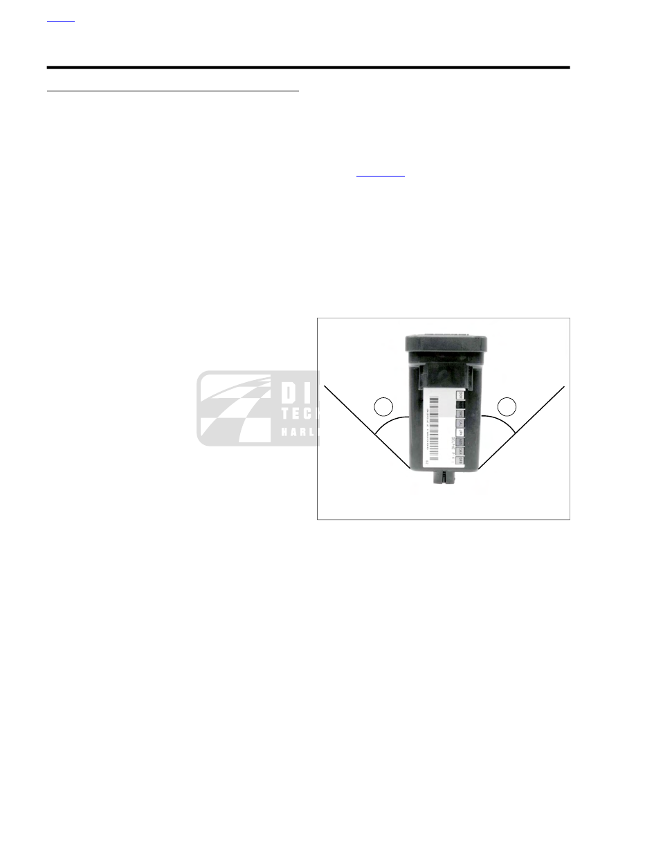
See 

Figure 5-13

The turn signals will cancel within two

seconds upon turn completion. A sensor inside the
TSM/TSSM/HFSM cancels the signal after the vehicle has
been returned to an upright position.

NOTE

The bank angle cancellation function has an automatic calibra-
tion feature. Ride the vehicle for 0.25 mile (0.4 km) at steady
speeds (upright) to calibrate the system. Performance of bank
angle function may not be optimal until this calibration is per-
formed. This self-calibration is performed automatically every
time the vehicle is started and ridden.

1

2

ed01792

1.

Left 45 degrees

2.

Right 45 degrees

Figure 5-13. Tilting TSM/HFSM

Four-Way Flashing

Use the following method to activate the four-way flashers:

1.

With the ignition switch ON and the security system dis-
armed (models with security only), press the left and right
turn signal switches at the same time.

2.

Turn the ignition switch OFF and arm the security system
if present and desired. The four-way flashers will continue
for two hours.

3.

To cancel four-way flashing, disarm the security system
if necessary, turn the ignition switch ON and press the left
and right turn signal switches at the same time.

This system allows a stranded vehicle to be left in the four-way
flashing mode and secured until help is found.

If the security system is disarmed while the four-way flashers
are active, the lights will flash as follows:

HOME

5-16  2011 Touring Diagnostics:  Accessories, Horn, Lighting and Security

1.

TSSM/HFSM stops four-way flashing mode. Vehicle sits
for 1 second with turn signals off.

2.

TSSM/HFSM performs disarming confirmation (1 flash).

3.

Vehicle sits for 1 second with turn signals off.

4.

Vehicle restarts four-way flashing mode.

GND

GND

Power

Turn

Turn

[7A]

[7B]

[31A]

[31B]

[20A]

[20B]

[21B]

[21A]

[30B]

[30A]

[24B]

[24A]

[22B]

[22A]

1

5

1

5

1

5

1

5

Right Turn

Switch

Left Turn

Switch

Battery

Ignition

Left Turn Feed Output

1
2
5

Right Turn Feed Output

6

Right Turn Switch Input

7

GY

TSM/HFSM

12

Ground

8

1
2
5
6
7

12

8

Left

Turn

Switch Input

BN/GY

BN/GY

BK/GN

BK/GN

BK/GN

W/V

W/BN

BN

V

2F

2E

1F

1E

2D

2C

1D

1C

Ignition 15A

[64-2B]

[64-1B]

Lights

Battery15A

Accessories 15A

R/GY

R

R/BK

R/BK

O/W

O/W

W/V

W/V

W/BN

W/BN

O/W

O/W

BE

GY

Right GND 2

Left GND 1

O/W

Right Rear

Turn

Lamp

Right Turn

And DOM

Running Lamp

Left Turn

And DOM

Running Lamp

Left Rear

Turn

Lamp

2

1

1

2

3

5

6

1

2

3

5

6

1

3

5 6 7

1

3

5 6 7

2

1

1
2

1
2

BK

V/BN

BK

V/BN

[19A]

[18A]

[19B]

[18B]

[94B]

[94A]

BK

BK

BN

V

BK

BK

BK

BK

BN

BE

BE

BN

BN

V

V

BN

V

V

BK

BN

BE

BE

V

BK

BN

BE

V

BK

BN

BE

V

BK

BN

BE

V

7

4

1

7

4

1

1

2

3

4

5

6

1

2

3

4

5

6

5

12

9

5

12

9

Indicator

Lamps

Right

Turn

Left

Turn

em00850

Figure 5-14. Turn Signal Circuit: FLHR/C

HOME

2011 Touring Diagnostics:  Accessories, Horn, Lighting and Security  5-17

Left Turn

And DOM

Running

Lamp

Facia/

Converter

Module

1

3

5

1

3

5

BK

BK

BK

BN

BN

BN

BK

V

BK

BN

V

V

V

[257A]

[257B]

[7A]

[7B]

6

5

2

BK

BN

V

V

V

V

V

V

V

BN

[226B]

[226A]

[94B]

BK

BK

BN

BN

V

V

6

5

2

[94B]

1

3

5

1

3

5

2

5

4

2

5

4

[7A]

[7B]

[257A]

[257B]

1

3

4

1

3

4

1

4

5

1

4

5

7

7

1

3

4

1

3

4

7

7

BK

BN

BK

BK

BK

BK

BK

BN

BN

BN

[262A]

[262B]

Facia/

Converter

Module

BK

[257A]

[257B]

V

V

V

V

Y

BN

[226B]

[226A]

1

3

4

1

3

4

1

2

5

1

2

4

5

6

6

7 11

1

3

4

1

3

4

7

7

BK

BK

BK

BK

BK

BN

BN

[262A]

[262B]

(FL/TRX/HX)

(DOM)

(HDI)

(FL/TRX/HX

Canada Only)

6

5

2

[94B]

V/BN

1

4

7

11

GN

[262B]

GN/W

[94A]

[30B]

[30A]

(FL/HTCU/HTK/TRU)

(FLHTC Only)

[24B]

[24A]

[22B]

[22A]

1

5

1

5

1

5

1

5

Right Turn

Switch

Left Turn

Switch

Battery

Ignition

Left Turn Feed Output

1
2
5

Right Turn Feed Output

6

Right Turn Switch Input

7

GY

TSM/HFSM

12

Ground

8

1
2
5
6
7

12

8

Left

Turn

Switch Input

BN/GY

BN/GY

BK/GN

BK/GN

W/V

W/BN

BN

V

2F

2E

1F

1E

2D

2C

1D

1C

Ignition 15A

[64-2B]

[64-1B]

Lights

Battery15A

Accessories 15A

R/GY

R

R/BK

R/BK

O/W

O/W

W/V

W/V

W/BN

W/BN

O/W

O/W

BK

BK

BK

BE

BE

BE

GY

BK

BK

BE

BE

BK

BK

BE

BE

BK

BN

V

B

D

B

D

3 2

3 2

3 2 1

1

1

1

3 2

RH Front

Turn Signal

Right Turn

And DOM

Running

Lamp

Left

GND 1

Right

GND 2

LH Front

Turn Signal

[15B]

[15A]

[31LA]

[31LB]

[31RA]

[31RB]

V/BK

V/BN

BK

BK

BN

BN

BN

O/W

O/W

O/W

W/V

W/V

V

BN

V

BN

V

V

BK

V

BN

V

W/BN

W/BN

5

7

8

10

11

5

7

8

10

11

5 4

1

4

1

Indicator

Lamps

Right

Turn

Left

Turn

[21B]

[21A]

[1B]

[1A]

Right Rear

Turn

Lamp

Left Rear

Turn

Lamp

2

1

1

2

3

4

5

6

2

1

1
2

1
2

BK

V/BN

BK

V/BN

[19A]

[18A]

[19B]

[18B]

Y/W

em00824

Figure 5-15. Turn Signal Circuit: Except FLHR/C

HOME

5-18  2011 Touring Diagnostics:  Accessories, Horn, Lighting and Security

WILL NOT CANCEL UPON TURN
COMPLETION, NO DTCS

Table 5-11. Will Not Cancel Upon Turn Completion, No

DTCs Diagnostic Faults

POSSIBLE CAUSES

Improper configuration

TSM/TSSM/HFSM malfunction

1. TSM/TSSM/HFSM Mounting Test

1.

Verify TSM/TSSM/HFSM is mounted correctly.

2.

Is TSM/TSSM/HFSM mounted correctly?

a.

Yes.

Go to Test 2.

b.

No. Mount correctly.

2. Correct Configuration Test

1.

Check if TSM/TSSM/HFSM is configured correctly. See

5.15 SERVICE AND EMERGENCY FUNCTIONS AND
CONFIGURATIONS

.

2.

Proper configuration?

a.

Yes.

Go to Test 3.

b.

No. Select proper vehicle configuration.

3. 4-Way Cancellation Test

1.

Gain access to the vehicle's TSM/TSSM/HFSM.

2.

See 

Figure 5-13

. Position TSM/TSSM/HFSM in the same

orientation it is mounted on the vehicle.

3.

With IGN ON, turn on 4-way flashers by depressing both
left and right turn signal switches at the same time.

4.

Turn IGN OFF. The 4-way flashers should continue to
flash.

5.

Tilt the module greater than 45 degrees to the left.

6.

Repeat steps 2-4 then tilt the module greater than 45
degrees to the right.

7.

Do 4-way flashers cancel in both directions?

a.

Yes.

Go to Test 4.

b.

No. Replace TSM/TSSM/HFSM. See the service
manual. (6773)

4. Turn Signals Cancel Test

1.

Operate vehicle at a speed greater than 7 mph (11.2 km/h)
in a straight line.

2.

Activate either turn signal.

3.

Turn signals should cancel after 20 flashes.

4.

Do turn signals cancel?

a.

Yes. System operating properly.

b.

No.

Go to Test 5.

5. Speedometer Test

1.

Does speedometer register vehicle speed?

a.

Yes. Replace TSM/TSSM/HFSM. See the service
manual. (6773)

b.

No. See 

2.1 INITIAL DIAGNOSTICS

.

FLASH AT DOUBLE NORMAL RATE, ALL
BULBS WORK, NO DTCS

TOOL NAME

PART NUMBER

ELECTRICAL CONTACT LUBRICANT

99861-02

Table 5-12. Flash at Double Normal Rate, All Bulbs Work,

No DTCs Diagnostic Faults

POSSIBLE CAUSES

Incorrect lamps

TSM/TSSM/HFSM malfunction

Lamp malfunction

1. Lamp Load Calibration Test

1.

Disconnect the negative battery cable for at least one
minute.

2.

Connect the negative battery cable.

3.

Turn IGN ON.

4.

Activate the left turn signals for more than four flashes.

5.

Activate the right turn signals for more than four flashes.

6.

Did the turn signals calibrate?

a.

Yes.

Go to Test 2.

b.

No. Correct issue and recalibrate.

2. Lamp Verification Test

1.

Determine correct part number for all installed turn signal
bulbs.

2.

Verify correct parts are installed on vehicle.

3.

Are the correct parts installed?

a.

Yes.

Go to Test 3.

b.

No. Replace with correct bulbs. See the service
manual. (6820)

3. Bulb Corrosion Test

1.

Check for corrosion on bulbs and/or sockets.

2.

Is corrosion present?

a.

Yes.

Go to Test 6.

b.

No.

Go to Test 4.

4. Lamp Connection Terminal Corrosion
Test

1.

Check for corrosion on all lamp connection terminals.

HOME

2011 Touring Diagnostics:  Accessories, Horn, Lighting and Security  5-19

2.

Is corrosion present?

a.

Yes.

Go to Test 5.

b.

No. Replace TSM/TSSM/HFSM. See the service
manual. (6791)

5. Verification Test

1.

Clean corrosion from wires and terminals.

2.

Do lamps flash at normal rate?

a.

Yes. System OK. (6822)

b.

No. Replace TSM/TSSM/HFSM. See the service
manual. (6791)

6. Lamp Operation Test

1.

Remove corrosion with a wire brush.

2.

Install ELECTRICAL CONTACT LUBRICANT (Part
No. 99861-02) in bulb sockets.

3.

Do lamps flash at normal rate?

a.

Yes. System OK. (6822)

b.

No.

Go to Test 7.

7. Lamp Assembly Test

1.

Clean or replace bulb.

2.

Do lamps flash at normal rate?

a.

Yes. System OK.  (6822)

b.

No. Replace lamp assembly. See the service manual.
(6823)

BOTH TURN SIGNAL LAMPS ON ONE SIDE
INOPERATIVE, NO DTCS

TOOL NAME

PART NUMBER

BREAKOUT BOX

HD-42682

Table 5-13. Both Turn Signal Lamps on One Side

Inoperative, No DTCs Diagnostic Faults

POSSIBLE CAUSES

Open on turn signal inputs

Open accessory circuit

Left turn signal switch malfunction

Right turn signal switch malfunction

TSM/TSSM/HFSM malfunction

1. Left or Right Turn Signal Malfunction Test

1.

With IGN ON, operate the left and right turn signals.

2.

Are the right turn signals inoperative?

a.

Yes.

Go to Test 2.

b.

No.

Go to Test 5.

2. Right Turn Signal Circuit Test

1.

With IGN OFF, connect BREAKOUT BOX (Part No. HD-
42682) between wire harness connector [30B] and
TSM/TSSM/HFSM [30A]. See 

1.2 DIAGNOSTIC TOOLS

.

2.

Turn IGN ON.

3.

While pressing the right turn signal switch, using a multi-
meter, test for voltage on breakout box (gray) terminal 7.

4.

Is battery voltage present when switch is pressed?

a.

Yes.

Go to Test 8.

b.

No.

Go to Test 3.

3. Right Turn Signal Switch Test

1.

Disconnect right hand controls [22].

2.

Test for voltage between [22B] terminal 1 and ground.

3.

Is battery voltage present?

a.

Yes.

Go to Test 4.

b.

No. Repair open in (O/W) wire. (5041)

4. Right Turn Signal Circuit Continuity Test

1.

Turn IGN OFF.

2.

Test for continuity between [22B] terminal 5 and breakout
box (gray) terminal 7.

3.

Is continuity present?

a.

Yes. Replace the right turn signal switch. See the
service manual. (6811)

b.

No. Repair open in (W/BN) wire. (5041)

5. Left Turn Signal Circuit Test

1.

With IGN OFF, connect BREAKOUT BOX (Part No. HD-
42682) between wire harness connector [30B] and
TSM/TSSM/HFSM [30A]. See 

1.2 DIAGNOSTIC TOOLS

.

2.

Turn IGN ON.

3.

While pressing the left turn signal switch, using a multi-
meter, test for voltage on breakout box (gray) terminal 8.

4.

Is battery voltage present when switch is pressed?

a.

Yes.

Go to Test 9.

b.

No.

Go to Test 6.

6. Left Turn Signal Switch Test

1.

Disconnect left hand controls [24].

2.

Test for voltage between [24B] terminal 1 and ground.

3.

Is battery voltage present?

a.

Yes.

Go to Test 7.

b.

No. Repair open in (O/W) wire. (5043)

7. Left Turn Signal Circuit Continuity Test

1.

Turn IGN OFF.

2.

Test for continuity between [24B] terminal 5 and breakout
box (gray) terminal 8.

HOME

5-20  2011 Touring Diagnostics:  Accessories, Horn, Lighting and Security

3.

Is continuity present?

a.

Yes. Replace the left turn signal switch. See the ser-
vice manual. (6811)

b.

No. Repair open in (W/V) wire. (5041)

8. Right Turn Signal Short to Voltage Test

1.

Release the right turn signal switch.

2.

Test for voltage on breakout box (gray) terminal 7.

3.

Is battery voltage present?

a.

Yes. Repair short to voltage on (W/BN) wire.

b.

No, without anti-theft tracking module. Replace
the TSM/TSSM/HFSM. See the service manual.

c.

No, with anti-theft tracking module.

Go to Test 10.

9. Left Turn Signal Short to Voltage Test

1.

Release the left turn signal switch.

2.

Test for voltage on breakout box (gray) terminal 8.

3.

Is battery voltage present?

a.

Yes. Repair short to voltage on (W/V) wire.

b.

No, without anti-theft tracking module. Replace
the TSM/TSSM/HFSM. See the service manual.

c.

No, with anti-theft tracking module.

Go to Test 10.

10. Anti-Theft Tracking Module Test

1.

Disconnect anti-theft tracking module.

2.

Press the inoperative turn signal switch.

3.

Do the turn signals function properly?

a.

Yes. Replace the anti-theft tracking module. See the
service manual.

b.

No. Replace the TSM/TSSM/HFSM. See the service
manual.

ONE TURN SIGNAL LAMP INOPERATIVE,
NO DTCS

TOOL NAME

PART NUMBER

HARNESS CONNECTOR TEST KIT

HD-41404-C

Table 5-14. One Turn Signal Lamp Inoperative, No DTCs

Diagnostic Faults

POSSIBLE CAUSES

Open turn signal circuit

Open turn signal ground circuit

Inoperative turn signal

TSM/TSSM/HFSM malfunction

1. Inoperative Signal Location Test

1.

With IGN ON, operate the left and right turn signals.

2.

Do all the turn signals operate on both sides?

a.

Yes. System operating properly.

b.

No, right front turn signal inoperative.

Go to Test

2.

c.

No, left front turn signal inoperative.

Go to Test 5.

d.

No, right rear turn signal inoperative.

Go to Test

8.

e.

No, left rear turn signal inoperative.

Go to Test 11.

2. Right Front Turn Signal Bulb Test

1.

Remove the right front turn signal bulb.

2.

Inspect the bulb.

3.

Is the bulb good?

a.

Yes.

Go to Test 3.

b.

No. Replace the bulb. See the service manual. (6820)

3. Right Front Turn Signal Circuit Test

1.

Disconnect front turn signal [31] (FLHR/C) or [31R] (except
FLHR/C).

2.

Using HARNESS CONNECTOR TEST KIT (Part No. HD-
41404-C), connect a test light to [31A] (FLHR/C) or [31RA]
(except FLHR/C) between terminals 1 and 2.

3.

Press the right turn signal switch.

4.

Does the test light flash?

a.

Yes. Replace the right front turn signal. See the ser-
vice manual. (6823)

b.

No.

Go to Test 4.

4. Right Front Turn Signal Ground Circuit
Test

1.

Test for voltage between [31A] (FLHR/C) or [31RA] (except
FLHR/C) terminal 2 and ground.

2.

Does the voltage cycle on and off?

a.

Yes. Repair open in (BK) wire between [31A]
(FLHR/C) or [31RA] (except FLHR/C) terminal 1 and
ground. (5041)

b.

No. Repair open in (BN) wire between [31A] (FLHR/C)
or [31RA] (except FLHR/C) terminal 2 and
TSM/TSSM/HFSM. (5041)

5. Left Front Turn Signal Bulb Test

1.

Remove the left front turn signal bulb.

2.

Inspect the bulb.

3.

Is the bulb good?

a.

Yes.

Go to Test 6.

b.

No. Replace the bulb. See the service manual. (6820)

6. Left Front Turn Signal Circuit Test

1.

Disconnect front turn signal [31] (FLHR/C) or [31L] (except
FLHR/C).

HOME

2011 Touring Diagnostics:  Accessories, Horn, Lighting and Security  5-21

2.

Using HARNESS CONNECTOR TEST KIT (Part No. HD-
41404-C), connect a test light to [31A] between terminal
5 and terminal 6 (FLHR/C) or [31LA] between terminal 2
and terminal 3 (except FLHR/C).

3.

Press the left turn signal switch.

4.

Does the test light flash?

a.

Yes. Replace the left front turn signal. See the service
manual. (6823)

b.

No.

Go to Test 7.

7. Left Front Turn Signal Ground Circuit Test

1.

Test for voltage between [31A] (FLHR/C) terminal 5 and
ground or [31LA] (except FLHR/C) terminal 2 and ground.

2.

Does the voltage cycle on and off?

a.

Yes. Repair open in (BK) wire between [31A] terminal
6 and ground (FLHR/C) or [31LA] terminal 3 and
ground (except FLHR/C). (5041)

b.

No. Repair open in (V) wire between [31A] terminal
5 and TSM/TSSM/HFSM (FLHR/C) or [31LA] terminal
2 and TSM/TSSM/HFSM (except FLHR/C). (5041)

8. Right Rear Turn Signal Bulb Test

1.

Remove the right rear turn signal bulb.

2.

Inspect the bulb.

3.

Is the bulb good?

a.

Yes.

Go to Test 9.

b.

No. Lamp is LED.

Go to Test 15.

c.

No. Bulb does not work. Replace the bulb. See the
service manual. (6820)

9. Right Rear Turn Signal Circuit Test:
Except LED Lights

1.

Disconnect right rear turn signal [18] (except FLTRX/FLHX)
or [262] (FLTRX/FLHX).

2.

Using HARNESS CONNECTOR TEST KIT (Part No. HD-
41404-C), connect a test light to [18A] terminal 1 and ter-
minal 2 or [262A] terminal 1 and terminal 6.

3.

Press the right turn signal switch.

4.

Does the test light flash?

a.

Yes. Replace the right rear turn signal. See the ser-
vice manual. (6823)

b.

No.

Go to Test 10.

10. Right Rear Turn Signal Ground Circuit
Component Test

1.

Disconnect rear fender lights [94] (except FLTRX/FLHX)
or [226] (FLTRX/FLHX).

2.

Test for voltage between [94B] terminal 2 and terminal 6
or [226B] terminal 3 and terminal 7.

3.

Does the voltage cycle off and on?

a.

Yes. Except FLTRX/FLHX. Replace the circuit board.
See the service manual. (5215)

b.

Yes. FLTRX/FLHX. Replace the facia/converter
module. See the service manual. (6809)

c.

No.

Go to Test 14.

11. Left Rear Turn Signal Bulb Test

1.

Remove the left rear turn signal bulb.

2.

Inspect the bulb.

3.

Is the bulb good?

a.

Yes.

Go to Test 12.

b.

No. Lamp is LED.

Go to Test 17.

c.

No. Bulb does not work. Replace the bulb. See the
service manual. (6820)

12. Left Rear Turn Signal Circuit Test:
Except LED Lights

1.

Disconnect left rear turn signal [19] (except FLTRX/FLHX)
or rear lighting jumper harness [262] (FLTRX/FLHX).

2.

Using HARNESS CONNECTOR TEST KIT (Part No. HD-
41404-C), connect a test light to [19A] terminal 1 and ter-
minal 2 or [262A] terminal 2 and terminal 5.

3.

Press the left turn signal switch.

4.

Does the test light flash?

a.

Yes. Replace the left rear turn signal. See the service
manual. (6823)

b.

No.

Go to Test 13.

13. Left Rear Turn Signal Component Test

1.

Test for voltage between [94B] terminal 5 and terminal 6
or [226B] terminal 1 and terminal 4.

2.

Does the voltage cycle off and on?

a.

Yes. Except FLTRX/FLHX. Replace the circuit board.
See the service manual. (5215)

b.

Yes. FLTRX/FLHX. Replace the facia/converter
module. See the service manual. (6809)

c.

No.

Go to Test 16.

14. Right Rear Turn Signal Ground Circuit
Test

1.

Test for voltage between [94] terminal 2 or [226] terminal
3 and ground.

2.

Does the voltage cycle on and off?

a.

Yes. Repair open in the (BK) wire. (5041)

b.

No. Repair open in the (BN) wire. (5041)

15. Right Rear Turn Signal Circuit Test: LED
Lights

1.

Disconnect rear lighting jumper harness [262].

HOME

5-22  2011 Touring Diagnostics:  Accessories, Horn, Lighting and Security

2.

Test for voltage at [262A] between terminal 1 and terminal
5.

3.

Does the voltage cycle on and off?

a.

Yes. Replace the lightbar. See the service manual.
(6823)

b.

No.

Go to Test 10.

16. Left Rear Turn Signal Ground Circuit
Test

1.

Test for voltage between [94] terminal 5 or [226] terminal
4 and ground.

2.

Does the voltage cycle on and off?

a.

Yes. Repair open in the (BK) wire. (5041)

b.

No. Repair open in the (V) wire. (5041)

17. Left Rear Turn Signal Circuit Test: LED
Lights

1.

Disconnect rear lighting jumper harness [262].

2.

Test for voltage at [262A] between terminal 2 and terminal
5.

3.

Does the voltage cycle on and off?

a.

Yes. Replace the lightbar. See the service manual.
(6823)

b.

No.

Go to Test 12.

HOME

2011 Touring Diagnostics:  Accessories, Horn, Lighting and Security  5-23

5.7

HEADLAMPS

DESCRIPTION AND OPERATION

When the ignition is turned ON the headlamp switch receives
power through the lights fuse.

In the low position the headlamp switch directs voltage
through the (Y) wire to illuminate the low beam headlamp.

In the high position voltage is directed through the (W)
wire to the high beam headlamp and the high beam
indicator.

See 

Figure 5-16

 and 

Figure 5-17

The headlamp could have

one (FLH models) or two (FLT models) connectors depending
on the model. Most models have a single connector for the low
and high beam headlamp. However, the FLT model has a left
assembly connector and a right assembly connector.

1

2

3

4

5

6

7

8

10

9

11

ed03110

1.

Front turn signals [31]

2.

Accessories off/on switch [67]

3.

Left hand controls [24]

4.

Left cruise controls [158]

5.

Front wheel speed sensor [167]

6.

Head lamp [38]

7.

Twist grip sensor [204]

8.

Right cruise controls [159]

9.

Passing lamps off/on switch [109]

10. Right hand controls [22]
11. Passing lamps [73]

Figure 5-16. Head Lamp Nacelle: FLH Models

1

2

4

3

ed03072

1.

HDI position lamp [29-2]

2.

HDI position lamp [29-1]

3.

Headlamp [38R]

4.

Headlamp [38L]

Figure 5-17. Headlamp: FLT Models

Diagnostic Tips

If the headlight fuse is open, test for short to ground on (BE)
wire from the fuse to the headlamp switch. Also, check for a
short to ground on the (W) wire from the headlamp switch. If
this circuit is grounded, it will open the fuse when the headlamp
switch is in the high position.

Connector Information

For additional information about the connectors in the following
diagram(s) and diagnostic procedure(s), including the color of
the harness test kit terminal probes, see 

B.1 CONNECTORS

.

HOME

5-24  2011 Touring Diagnostics:  Accessories, Horn, Lighting and Security

BK/GN

[20B]

[20A]

High

Low

BE

BK

BK

BK

BK

BK

BE

BE

Y

Y

Y

Y

W

W

W

Y

W

Headlamp

GND 1

GND 1

Chassis

Ground

BK

BK

BK

W

W

W

High Beam

Indicator

Turn Signal

Indicators

Headlamp

Hi/Lo

Switch

FLHR/C

Low

High

[109B]

[109A]

[73B]

[73A]

2D

2C

[64-2B]

Headlamp

15A

Ignition

Power

R/BK

2

4

2

4

[21A]

[21B]

2

7

2

7

3

3

BE

BE

BE

BE

Y

W

Y

W

Headlamp

Hi/Lo

Switch

Low

High

[24B]

[24A]

2D

2C

[64-2B]

Headlamp

15A

Ignition

Power

R/BK

2

4

2

4

3

3

3

3

1

4

4

3

3

2

2

1

1

2

2

1

1

3

1

3

2

2

High

Low

BK

Y

W

Headlamp

FLT Models Only

1

3

1

3

2

2

High

Low

BK

Y

W

BK

BK

Y

W

BK

Y

Y

Y

Y

W

Headlamp

1

2

1

3

2

2

BK/GN

BK/GN

BK/GN

W

10

5

10

5

BK

BK

BK

W

W

BK

BK

BK

BK

W

High Beam

Indicator

Turn Signal

Indicators

3

5

3

5

Sensor

Grounds

GND 2

Toggle

Switch

Auxiliary

Lights

Auxiliary

Lights

GY/BK

GY/BK

GY/BK

GY/BK

GY/BK

GY/BK

GY/BK

GY/BK

[31RB]

[31RA]

[31LB]

[31LA]

4

4

4

4

Auxiliary

Lights

Auxiliary

Lights

GY/BK

GY/BK

GY/BK

GY/BK

[21B]

[21A]

[105B]

[105A]

[2B]

[2A]

[24B]

[24A]

6

6

7

8

7

8

Except

FLHR/C

[38A]

[38B]

[38A]

[38B]

[38A-2]

[38B-2]

em00851

Figure 5-18. Headlamp

HOME

2011 Touring Diagnostics:  Accessories, Horn, Lighting and Security  5-25

HEADLAMP INOPERATIVE, NO DTCS

TOOL NAME

PART NUMBER

HARNESS CONNECTOR TEST KIT

HD-41404-C

Table 5-15. Headlamp Inoperative, No DTCs Diagnostic

Faults

POSSIBLE CAUSES

Open fuse

Open power to switch circuit

Headlamp Hi/Lo switch malfunction

Open ground circuit

Open high beam power circuit

Open low beam power circuit

Headlamp malfunction

1. Operational Test

1.

Turn IGN ON.

2.

Move the headlamp switch to the high and low positions.

3.

Do the headlamps work in both positions?

a.

Yes. Concern is intermittent perform wiggle test. See

1.3 DIAGNOSTICS AND TROUBLESHOOTING,
Wiggle Test

.

b.

No. High beam headlamp inoperative.

Go to Test

2.

c.

No. Low beam headlamp inoperative.

Go to Test

5.

d.

No. Both headlamps inoperative.

Go to Test 7.

2. High Beam Indicator Test

1.

With the headlamp Hi/Lo switch in the high position,
observe the high beam indicator lamp.

2.

Does the high beam indicator illuminate?

a.

Yes.

Go to Test 4.

b.

No.

Go to Test 3.

3. Headlamp High Beam Circuit Switch Test

1.

With IGN OFF, disconnect left hand controls [24].

2.

Place the headlamp Hi/Lo switch in the high position.

3.

Using a HARNESS CONNECTOR TEST KIT (Part No. HD-
41404-C), jumper [24B] terminals 3 and 4 together.

4.

Turn IGN ON.

5.

Does the high beam headlamp operate?

a.

Yes. Replace the left switch assembly. See the ser-
vice manual. (5171)

b.

No. Repair open in (W) wire between [24B] and the
indicators. (5041)

4. High Beam Headlamp Test

1.

Disconnect the high beam headlamp.

2.

With the IGN ON and the headlamp Hi/Lo switch in the
high position, using HARNESS CONNECTOR TEST
KIT (Part No. HD-41404-C) and a multimeter, test for
voltage between [38A] (FLH models) or [38A-2] (FLT
models) terminals 1 and 3.

3.

Is battery voltage present?

a.

Yes. Replace the headlamp. See the service manual.
(5185)

b.

No. Repair open in (W) wire to headlamp. (5041)

5. Headlamp Low Beam Switch Test

1.

With the IGN OFF, disconnect left hand controls [24].

2.

Using a HARNESS CONNECTOR TEST KIT (Part No. HD-
41404-C), jumper [24B] terminals 2 and 3 together.

3.

Turn IGN ON.

4.

Does the low beam headlamp operate?

a.

Yes. Replace the left switch assembly. See the ser-
vice manual. (5171)

b.

No.

Go to Test 6.

6. Low Beam Headlamp Test

1.

Connect [24].

2.

Disconnect the low beam headlamp.

3.

With the headlamp Hi/Lo switch in the low position using
HARNESS CONNECTOR TEST KIT (Part No. HD-41404-
C) and a multimeter, test for voltage between [38A] (FLH
models) or [38A-2] (FLT models) terminals 2 and 3.

4.

Is battery voltage present?

a.

Yes. Replace the headlamp. See the service manual.
(5185)

b.

No. Repair open in (Y) wire to headlamp. (5041)

7. High Beam Indicator Test

1.

With the headlamp Hi/Lo switch in the high position,
observe the high beam indicator lamp.

2.

Does the high beam indicator illuminate?

a.

Yes. Repair open in (BK) ground circuit from head-
lamp. (5041)

b.

No.

Go to Test 8.

8. Headlamp Power Circuit Open Test

1.

With the IGN OFF, disconnect left hand controls [24].

2.

Using a HARNESS CONNECTOR TEST KIT (Part No. HD-
41404-C), jumper [24B] terminals 2 and 3 together.

3.

Turn IGN ON.

4.

Does the low beam headlamp operate?

a.

Yes. Replace the left switch assembly. See the ser-
vice manual. (5171)

b.

No. Repair open in (BE) wire to [24B]. (5039)

HOME

5-26  2011 Touring Diagnostics:  Accessories, Horn, Lighting and Security

9. Headlamp Fuse Test

1.

Inspect the headlamp fuse.

2.

Is the fuse good?

a.

Yes.

Go to Test 9.

b.

No.

Go to Test 10.

10. Power Circuit Test

1.

Test for voltage on [64-2B] socket terminal 2D of the
headlamp fuse.

2.

Is battery voltage present?

a.

Yes. Repair open in (BE) wire between fuse block
and headlamp Hi/Lo switch. (5039)

b.

No. Repair open in (R/BK) wire. (5041)

AUXILIARY LAMPS INOPERATIVE

Table 5-16. Auxiliary Lamps Inoperative Diagnostic Faults

POSSIBLE CAUSES

Auxiliary lamp malfunction

Toggle switch malfunction

Open in auxiliary power circuit

Open in auxiliary ground circuit

1. Auxiliary Lamps Operation Test

1.

Place the headlamp switch in the low position.

2.

Turn on the auxiliary lamps.

3.

Do the auxiliary lamps illuminate?

a.

Yes. System operating properly. Intermittent perform
wiggle test. See 

1.3 DIAGNOSTICS AND

TROUBLESHOOTING, Wiggle Test

.

b.

No. Auxiliary lamps and headlamps are inoper-
ative.
 See 

5.7 HEADLAMPS, Headlamp Inoperative,

No DTCs

.

c.

No. Only one auxiliary lamp is operative.

Go to

Test 2.

d.

No. Both auxiliary lamps are inoperative.

Go to

Test 4.

2. Auxiliary Bulb Test

1.

Inspect the bulb.

2.

Is the bulb good?

a.

Yes. FLHR/C.

Go to Test 3.

b.

Yes. Except FLHR/C.

Go to Test 6.

c.

No. Replace the bulb. See the service manual. (5227)

3. Auxiliary Lamp Circuit Test: FLHR/C

1.

Disconnect auxiliary lamps [73].

2.

Test for battery voltage between inoperative circuit at [73B]
terminal 1 or 2 and ground.

3.

Is battery voltage present?

a.

Yes. Replace the inoperative auxiliary lamp. (5227)

b.

No. Repair open in the (GY/BK) wire between the
toggle switch and [73]. (5041)

4. Auxiliary Lamp Switch Test

1.

Disconnect auxiliary lamp switch [109] (FLHR/C) models,
[105] on FLHT models.

2.

Jumper [109B] terminals 1 and 3 (FLHR/C) or [105A] ter-
minals 6 and 7 (FLHT) together.

3.

With the headlamp switch in the low position, turn IGN
ON.

4.

Do the auxiliary lamps illuminate?

a.

Yes. Replace the auxiliary lamp toggle switch. (5167)

b.

No. FLHR/C.

Go to Test 5.

c.

No. Except FLHR/C.

Go to Test 7.

5. Auxiliary Lamp Power Circuit Test:
FLHR/C

1.

Test for battery voltage from auxiliary lamp switch [109B]
terminal 1 (Y) to ground.

2.

Is battery voltage present?

a.

Yes. Repair open in (GY/BK) wire between [109B]
and [73B]. (5041)

b.

No. Repair open in (Y) wire between [109B] and
headlamp switch. (5041)

6. Auxiliary Lamp Circuit Test: Except
FLHR/C

1.

Disconnect left front turn signal [31L] or right front turn
signal [31R].

2.

Test for battery voltage between inoperative circuit at [31]
terminal 4 and ground.

3.

Is battery voltage present?

a.

Yes. Replace the inoperative auxiliary lamp. (5227)

b.

No. Repair open in the (GY/BK) wire between the
toggle switch and [31]. (5041)

7. Auxiliary Lamp Power Circuit Test: Except
FLHR/C

1.

Test for battery voltage from [105A] terminal 1 (Y) to
ground.

2.

Is battery voltage present?

a.

Yes. Repair open in (GY/BK) wire between [105A]
and [31]. (5041)

b.

No. Repair open in (Y) wire between [105A] and
headlamp switch. (5041)

HOME

2011 Touring Diagnostics:  Accessories, Horn, Lighting and Security  5-27

5.8

STOP LAMPS

DESCRIPTION AND OPERATION

The front stop lamp switch is a mechanical switch located in
the right handlebar switch assembly. See 

Figure 5-19

The

rear stop lamp switch is a pressure switch located on the right
side at the rear of the crankcase.

The brake switches receive power through the ACCY fuse. On
vehicles without ABS, When the front or rear stop lamp switch
is applied, voltage travels through the switch to the coil side of
the brake relay.

On vehicles with ABS the voltage from the stop lamp switch is
sent to the ABS module and also through an ABS diode pack
to the coil side of the brake relay.

The diode pack isolates the front and rear stop lamp voltages
so the ABS module can determine which stop lamp switch is
applied.

1

2

3

ed03082

1.

Clutch cover

2.

Rear brake switch [121]

3.

Exhaust pipe

Figure 5-19. Rear Brake Switch

Diagnostic Tips

When testing for a short to ground due to an open fuse, check
the (R/Y) wire between the brake relay and the stop lamp. A
short to ground on these wires causes the brake fuse to open
only when the brake switches are closed. A short to ground in
the (Y/BK) wire between the horn switch and the horn causes
the ACCY fuse to open when the horn switch is pressed and
needs to be checked for a short to ground as well.

Connector Information

For additional information about the connectors in the following
diagram(s) and diagnostic procedure(s), including the color of
the harness test kit terminal probes, see 

B.1 CONNECTORS

.

HOME

5-28  2011 Touring Diagnostics:  Accessories, Horn, Lighting and Security

Brake Light

Stop

Tour-Pak

Stop Lamps

Rear Lighting

Tail Lamp

3

4

4
3

4

6

BK

BK

R/Y

R/Y

R/Y

[94A]

[93B]

[93A]

Facia/

Converter

Module

5

6

5

6

BK

R/Y

R/Y

R/Y

R/Y

R/Y

BK

[7A]

[7B]

6

4

[226B]

[226A]

[94B]

R/Y

BK

6

4

[94B]

3

4

5

3

4

5

1

5

7

1

5

7

BK

BK

BK

BK

BK

BK

[262A]

[262B]

(FL/TRX/HX HDI Only)

(FL/HTCU/HTK/TRU)

R/Y

BK

(FL/TRX/HX Canada Only)

R/Y

4

5

4

5

3

2

3

2

BK

BK

BK

BK

BK

BK

R/Y

BK

[257A]

[257B]

4

5

4

5

[257A]

[257B]

Facia/

Converter

Module

R/Y

R/W

Y/W

R/Y

R/Y

O/W

O/W

[226B]

[226A]

3

4

9

3

4

9

1

5

7

1

5

7

BK

BK

BK

[262A]

[262B]

R/Y

R/Y

R/Y

R/Y

BK

R/Y

R/Y

R/Y

BK

4

5

4

5

[257A]

[257B]

(FL/TRX/HX DOM Only)

Facia/

Converter

Module

R/Y

R/Y

[226B]

[226A]

1

5

7

1

5

7

BK

BK

BK

BK

BK

R/Y

BK

4

5

2

1

2

1

1

25 Brake Switch Input

25

1

5

5

4

5

[257A]

[257B]

[7A]

[7B]

5

6

5

6

(FLHTC Only)

Rear

Stop

Lamp

Switch

Accessory

Power

Left GND 1

ECM

6

4

[94B]

Brake

15A

ACCY Fuse

15A

[64-1]

[64-2]

R/BE

O/W

O/W

O/V

O/V

O/W

O/W

R/BE

R/BE

R/BE

R/BE

R/BE

Accessory
Connector

BK

[78A]

[78B]

[1A]

[1B]

[22B]

[22B]

[22A]

2

1

O/W

R/BE

R/GY

R/GY

1A

1B

1C

1D

[121-2B]

[121-2A]

[121-1B]

[121-1A]

[12B]

[12A]

[12-5B]

[12-4B]

86

85

30

87

2

1

3

5

3B

2A

2B

3A

1

1

1

1

Pressure

Switch

Front

Stop Lamp

Switch

Except

FLHR

Brake
Relay

FLHR

R

V

1

2

5

6

[2A]

[2B]

V/BN

em00823

Figure 5-20. Stop Lamps without ABS

HOME

2011 Touring Diagnostics:  Accessories, Horn, Lighting and Security  5-29

Brake Light

Stop

Tour-Pak

Rear Marker/

Stop Lamps

Rear Lighting

Tail Lamp

3

4

4
3

4

6

BK

BK

R/Y

R/Y

R/Y

[94A]

[93B]

[93A]

Facia/

Converter

Module

5

6

5

6

BK

R/Y

R/Y

R/Y

R/Y

R/Y

BK

[7A]

[7B]

6

4

[226B]

[226A]

[94B]

R/Y

BK

6

4

[94B]

3

4

5

3

4

5

1

5

7

1

5

7

BK

BK

BK

BK

BK

BK

[262A]

[262B]

(FL/TRX/HX HDI Only)

(FL/HTCU/HTK/TRU)

R/Y

BK

(FL/TRX/HX Canada Only)

R/Y

4

5

4

5

BK

BK

BK

BK

R/Y

BK

[257A]

[257B]

4

5

4

5

[257A]

[257B]

Facia/

Converter

Module

R/Y

R/W

Y/W

R/Y

R/Y

O/W

O/W

[226B]

[226A]

3

4

9

3

4

9

1

5

7

1

5

7

BK

BK

BK

[262A]

[262B]

R/Y

R/Y

R/Y

R/Y

BK

R/Y

BK

4

5

4

5

[257A]

[257B]

(FL/TRX/HX DOM Only)

Facia/

Converter

Module

R/Y

R/Y

[226B]

[226A]

1

5

7

1

5

7

BK

BK

BK

BK

BK

R/Y

BK

4

5

2

1

2

1

1

25

Brake Switch Input

25

1

5

5

4

5

[257A]

[257B]

[7A]

[7B]

5

6

5

6

(FLHTC Only)

Rear Stop

Lamp Switch

ABS Diode

Pack

Accessory
Connector

ECM

[64-2]

Brake
Relay

Left GND 1

6

4

[94B]

Brake

15A

ACCY Fuse

15A

[64-1]

R/BE

O/W

O/W

O/V

O/V

O/W

O/W

R/BN

R/BE

R/BE

R/BE

R/BN

R/BN

R/BN

R/BE

BK

3

2

3

2

BK

BK

R/Y

R/Y

2

1

O/W

R/BN

R/GY

R/GY

1A

1B

1C

1D

[121-2B]

[121-2A]

[121-1B]

[121-1A]

[12-5B]

[12-4B]

86

85

30

87

2

1

3

5

3B

2A

2B

3A

1

1

1

1

Pressure

Switch

Front

Stop Lamp

Switch

Except

FLHR

FLHR

ABS

Module

R

V

1

2

5

6

4

3

2

1

4

3

2

1

13 Front Brake input

Rear Brake input

3

13

3

PK/BN

PK/BN

PK/BN

[166A]

[166B]

[2A]

[2B]

[201B]

[201A]

[78B]

[78A]

[12B]

[12A]

[22B]

[22A]

[1A]

[1B]

V/BN

em00822

Figure 5-21. Stop Lamps with ABS

HOME

5-30  2011 Touring Diagnostics:  Accessories, Horn, Lighting and Security

STOP LAMP INOPERATIVE

TOOL NAME

PART NUMBER

HARNESS CONNECTOR TEST KIT

HD-41404-C

Table 5-17. Stop Lamp Inoperative Diagnostic Faults

POSSIBLE CAUSES

Open fuse

Short in stop lamp circuit

Open power to switch circuit

Open ground circuit

Open stop lamp circuit

Stop lamp malfunction

Rear stop lamp switch malfunction

Front stop lamp switch malfunction

1. Accessory Circuit Test

1.

Turn IGN to ACC.

2.

Does the speedometer illuminate?

a.

Yes.

Go to Test 8.

b.

No.

Go to Test 2.

2. ACCY Fuse Test

1.

Inspect the ACCY fuse.

2.

Is the fuse good?

a.

Yes.

Go to Test 3.

b.

No.

Go to Test 5.

3. ACCY Circuit from Ignition Switch Test

1.

With IGN in ACC, using HARNESS CONNECTOR TEST
KIT (Part No. HD-41404-C) and a multimeter, test for
voltage between [64-1B] socket terminal 1C and ground.

2.

Is battery voltage present?

a.

Yes. Repair open in (O/W) wire from ACCY fuse.
(5043)

b.

No.

Go to Test 4.

4. Ignition Switch Test

1.

With IGN OFF, disconnect the ignition switch [33].

2.

Test for continuity between ignition switch [33B] terminal
1 and [64-1B] socket terminal 1C.

3.

Is continuity present?

a.

Yes. Replace the ignition switch. See the service
manual. (7287)

b.

No. Repair open between [64-1B] socket terminal 1C
and ignition switch [33B] terminal 1 (R/GY) wire.
(5041)

5. Accessory Circuit Resistance Test

1.

With the ACCY fuse removed, using HARNESS CON-
NECTOR TEST KIT (Part No. HD-41404-C) and a multi-

meter, measure resistance between [64-1B] socket ter-
minal 1D and ground.

2.

Is resistance less than 10 Ohms?

a.

Yes.

Go to Test 6.

b.

No. See diagnostic tips. Replace ACCY fuse and
verify repair. (6822)

6. Fuel Level Sensor Test

1.

Disconnect fuel tank harness [13].

2.

Measure resistance between [64-1B] socket terminal 1D
and ground.

3.

Is resistance less than 10 Ohms?

a.

Yes.

Go to Test 7.

b.

No. Replace fuel level sensor. See the service
manual. (6035)

7. Speedometer Test

1.

Disconnect the speedometer [39B].

2.

Measure resistance between [64-1B] socket terminal 1D
and ground.

3.

Is resistance less than 10 Ohms?

a.

Yes. Repair short to ground in accessory circuit (O/W)
wire. (5043)

b.

No. Replace the speedometer. See the service
manual. (6826)

8. Stop Lamp Switch Test

1.

Apply the front brake while observing the stop lamp.

2.

Apply the rear brake while observing the stop lamp.

3.

Does the stop lamp illuminate?

a.

Yes. Stop lamp illuminates only with front brake
applied.

Go to Test 12.

b.

Yes. Stop lamp illuminates only with rear brake
applied.

Go to Test 14.

c.

No.

Go to Test 9.

9. Brake Relay Test

1.

Test brake relay. See 

1.3 DIAGNOSTICS AND

TROUBLESHOOTING, Relay Diagnostics

.

2.

Does relay pass test?

a.

Yes.

Go to Test 10.

b.

No. Replace brake relay. See the service manual.
(1407)

10. Relay Coil Circuit Test

1.

Test for voltage between [64-2B] terminal 2A and terminal
3B.

2.

With the brake applied, is voltage present?

a.

Yes.

Go to Test 20.

b.

No.

Go to Test 11.

HOME

2011 Touring Diagnostics:  Accessories, Horn, Lighting and Security  5-31


Content      ..     11      12      13      14     ..