Harley Davidson 2011 Touring Models. Electrical Diagnostic Manual - page 11
4.4
NO INSTRUMENT POWER
DESCRIPTION AND OPERATION
. The speedometer and tachometer (if equipped)
receive battery power at terminal 5 and ignition power at ter-
minal 1. This is supplied through the battery fuse and the
instrument fuse located in fuse block [64]. Accessory power is
supplied through the ACCY fuse at terminal 6. The speedo-
meter and tachometer (if equipped) go through an initialization
sequence every time power is removed and re-applied to ter-
minal 1. The visible part of this sequence is the illumination of
check engine lamp, security lamp, backlighting, odometer and
fuel level. With IGN ON, the check engine lamp and security
lamp will illuminate for 4 seconds and then (if parameters are
normal) go out.
Loss of power on any of the inputs will change the instruments
behavior. Refer to
1
2
3
4
5
6
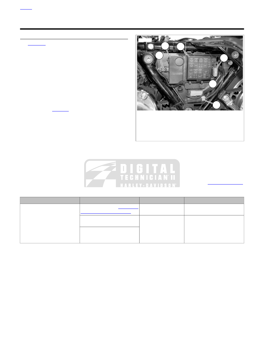
ed03111
1.
Security siren [142]
2.
Security siren (if equipped)
3.
Fuse block
4.
Main fuse [5]
5.
DLC [91]
6.
ABS diode pack [201] (if equipped)
Figure 4-4. Under Left Side Cover: Except FLTRX, FLHX,
FLHTC
Connector Information
For additional information about the connectors in the following
diagram(s) and diagnostic procedure(s), including the color of
the harness test kit terminal probes, see
Table 4-7. Function Chart - Loss of Input
TERMINAL 7 (GND)
TERMINAL 6 (ACC)
TERMINAL 1 (IGN)
TERMINAL 5 (BATTERY)
Instrument completely non-func-
tional
Speedometer non-func-
tional in ACC position.
Will not "WOW". See
Speedometer is non-functional
Diagnostics absent
Check engine, low fuel,
battery, cruise and ABS
lamps non-functional
Needles freeze, backlighting is
functional
Check engine lamp, low fuel and
battery lamp are non-functional.
Diagnostics absent.
4-8 2011 Touring Diagnostics: Instruments