Harley Davidson Softail 2000-2005. Service manual - page 23
 

  Главная      Harley Davidson     Harley Davidson Softail 2000-2005. Service manual


Search            copyright infringement  


Content      ..     21      22      23      24     ..


Harley Davidson Softail 2000-2005. Service manual - page 23


Installation

1. Install the flanges onto the correct side of the induction
module with the slotted hole at the top. Refer to the marks
made during

Removal

. Install

new

seals onto the induction

module.
2. Partially install the induction module and fuel line as-
sembly. Slide the fuel line connector (B, Figure 75) onto
the induction module fitting (C) until it clicks. Gently pull
on the fuel line to ensure the fitting is locked in place.
Slide the induction module on the upper two bolts.
3. Connect both throttle cables to the induction module as
described in this chapter.
4. Align the mounting flanges and install the two lower
bolts by hand. Use the same tool set up used to loosen the
bolts. Do not tighten the bolts at this time.
5. Working on the right side of the motorcycle, tighten
the lower two bolts until snug, do not tighten to the final
torque specification at this time. Use the same tool set up
used to loosen the bolts.
6. Working on the left side of the motorcycle, tighten the
upper two bolts to 71-124 in.-lb. (8-14 N•m).
7. Working on the right side of the motorcycle, tighten
the lower two bolts to 71-124 in.-lb. (8-14 N•m).
8. Carefully attach the electrical connector to each fuel
injector. Align the grooves in the female connector with
the tabs in the male space housing. Push the connector
halves together until both latches click.

NOTE

In Step 9, push the electrical connector
halves together until the female latches slot
connector is fully engaged with the tabs on
the male space housing.

9. Connect the following electrical connectors from the
induction module:

a. Fuel injectors.
b. Throttle position sensor (TP) (Figure 72).
c. Manifold pressure sensor (MAP).
d. Idle air control valve (IAC) (B, Figure 71).
e. Intake air temperature sensor (IAT) (A, Figure 71).

10. On California models, connect the EVAP hose to the
port on top of the induction module.
11. Install the air filter assembly as described in this
chapter.
12. Install the fuel tank as described in this chapter.

Inspection

Check the induction module assembly for wear, deteri-

oration or other damage. Replace the seals as a set if nec-

essary. The throttle housing is not serviceable and must be
replace if damaged.

THROTTLE AND IDLE CABLES

(CARBURETED MODELS)

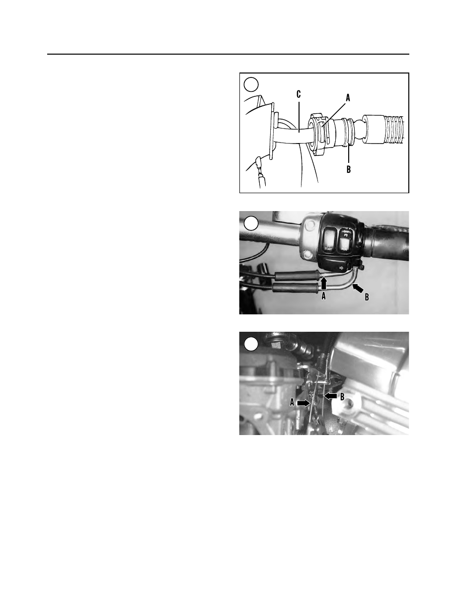
There are two different throttle cables. At the throttle

grip, the front cable is the throttle control cable (A, Figure
76
) and the rear cable is the idle control cable (B). At the

286

CHAPTER SEVEN

75

76

77

carburetor, the outboard cable is the throttle control cable
(A, Figure 77) and the inboard cable is the idle control ca-
ble (B).

Removal

1. Remove the fuel tank as described in this chapter.
2. Remove the air filter and backing plate as described in
this chapter.
3. Make a drawing or take a picture of the cable routing
from the carburetor through the frame to the right side
handlebar.
4. At the right side handlebar, loosen both control cable
adjuster locknuts (A, Figure 78), then turn the cable ad-
justers (B)

clockwise

as far as possible to increase cable

slack.

CAUTION

Failure to install the spacer in Step 5 will re-
sult in damage to the rubber boot and
plunger on the front brake switch.

5. Insert a 5/32 in. (4 mm) thick spacer between the brake
lever and lever bracket. Make sure the spacer stays in
place during the following steps.
6. Remove the screws securing the right side switch as-
sembly together (A, Figure 79).
7. Remove the front master cylinder (B, Figure 79) as de-
scribed in Chapter Thirteen.
8. Remove the brass ferrules from the notches on the in-
board side of the throttle grip (Figure 80). Remove the
ferrules from the cable end fittings.
9. Remove the friction shoe from the end of the tension
adjust screw.
10. Remove the throttle grip from the handlebar.

NOTE

Use a rocking motion while pulling on the
control cable housings in Step 11. If neces-
sary, place a drop of engine oil on the hous-
ings retaining rings to ease removal.

11. Pull the crimped inserts at the end of the throttle and
idle control cable housings from the switch lower hous-
ing.
12. Remove all clips and tie-wraps securing the throttle
and idle control cables to the frame.
13. Remove the cables from the right side of the steering
head and rubber trim (Figure 81).
14. Clean the throttle grip assembly and dry it thor-
oughly. Check the throttle slots for cracks or other dam-
age. Replace the throttle if necessary.

FUEL, EXHAUST AND EMISSION CONTROL SYSTEMS

287

7

79

80

81

78

15. The friction adjust screw is secured to the lower
switch housing with a circlip. If necessary, remove the
friction spring, circlip, spring and friction adjust screw.
Check these parts for wear or damage. Replace damaged
parts and reinstall. Make sure the circlip seats in the fric-
tion screw groove completely.
16. Clean the throttle area on the handlebar with solvent.

Installation

1. Apply a light coat of graphite to the housing inside sur-
faces and to the handlebar.
2. On the lower switch housing, push the larger diameter
silver throttle cable insert into the larger hole in front of
the tension adjust screw. Push it in until it snaps into place.
3. Push the smaller diameter gold throttle cable insert
into the smaller hole in the rear of the tension adjust screw.
Push it in until it snaps into place.
4. Position the friction shoe with the concave side facing
up and install it so the pin hole is over the point of the ad-
juster screw.
5. Install the throttle grip onto the handlebar. Push it on
until it stops, then pull it back about 1/8 in. (3.2 mm). Ro-
tate it until the ferrule notches are at the top.
6. Place the lower switch housing below the throttle grip.
Install the brass ferrules onto the cables so the end fittings
seat in the ferrule recess. Seat ferrules in their respective
notches on the throttle control grip. Make sure the cables
are captured in the molded grooves in the grip.
7. Assemble the upper and lower switch housings (A,
Figure 79) and the throttle grip. Install the lower switch
housing screws and tighten them finger-tight.
8. If it is not in place, insert the 5/32 in. (4 mm) thick
spacer between the brake lever and lever bracket. Make
sure the spacer stays in place during the following steps.
9. Install the front master cylinder (B, Figure 79) onto
the handlebar as described in Chapter Thirteen.
10. Securely tighten the switch housing screws.
11. Remove the cardboard insert from the front master
cylinder.
12. Operate the throttle and make sure both cables move
in and out properly.
13. Correctly route the cables (Figure 81) from the han-
dlebar, through the frame and to the carburetor.
14. Connect the idle cable to the carburetor as follows:

a. The idle cable has the small spring (A, Figure 82)

on the end of the cable.

b. Insert the idle cable sheath into the rear cable

bracket guide on the carburetor (B, Figure 82).

c. Attach the end of the idle cable into the throttle

wheel (C, Figure 82).

15. Connect the throttle cable to the carburetor as fol-
lows:

a. Insert the throttle cable sheath into the front cable

bracket guide on the carburetor.

b. Attach the end of the throttle cable to the throttle

wheel.

16. At the throttle grip, tighten the cables to keep the ca-
ble ends from being disconnected from throttle wheel.

17. Operate the hand throttle a few times. Make sure the
throttle barrel operates smoothly with no binding. Also

288

CHAPTER SEVEN

82

83

84

make sure both cable ends are seated squarely in their ca-
ble bracket guides and in the throttle barrel.

18. Adjust the throttle and idle cables as described in
Chapter Three.

19. Reinstall the carburetor as described in this chapter.

20. Install the air filter backplate and air filter as de-
scribed in this chapter.

21. Install the fuel tank as described in this chapter.

22. Start the engine and check for fuel leaks with the en-
gine idling. Then turn the handlebar from side to side. Do
not operate the throttle. If the engine speed increases

when turning the handlebar assembly, the throttle cables
are routed incorrectly or are damaged. Recheck cable
routing and adjustment.

WARNING

Do not ride the motorcycle until the throttle
cables are properly adjusted. Improper ca-
ble routing and adjustment can cause the
throttle to stick open. This could cause loss
of control.

STARTING ENRICHMENT VALVE (CHOKE)

CABLE REPLACEMENT

(CARBURETED MODELS)

1. Remove the air filter and backplate as described in
Chapter Three.
2. Note the routing of the enrichment cable from its
mounting bracket to the carburetor.
3. Loosen the locknut (A, Figure 83) and disconnect the
starting enrichment valve cable from the mounting
bracket (B). Move the end of the cable out of the mounting
bracket.
4. Partially remove the carburetor, as described in this
chapter, until the starting enrichment valve cable can be
disconnected from the backside of the carburetor.
5. Unscrew and remove the starting enrichment valve
and cable (Figure 84) from the carburetor and remove the
cable from the frame.
6. Install by reversing these removal steps. Note the fol-
lowing:

a. Align the starting enrichment valve needle (A, Fig-

ure 85) with the needle passage in the carburetor
(B) and install the starting enrichment valve.
Tighten the valve nut securely.

b. Position the starting enrichment valve cable into the

mounting bracket (B, Figure 83), then tighten the
locknut (A) securely.

THROTTLE AND IDLE CABLES

(EFI MODELS)

There are two different throttle cables. At the throttle

grip, the front cable is the throttle control cable (A, Figure
86
) and the rear cable is the idle control cable (B).

At the induction control module, the idle control cable

is located at the top of the throttle wheel (A, Figure 87)
and the throttle control cable (B) is located at the bottom.

Removal

1. Remove the fuel tank as described in this chapter.

FUEL, EXHAUST AND EMISSION CONTROL SYSTEMS

289

7

87

85

86

2. Remove the air filter and backing plate as described in
this chapter.
3. Make a drawing or take a picture of the cable routing
from the induction module through the frame to the right
side handlebar.
4. At the right side handlebar, loosen both control cable
adjuster locknuts (A, Figure 88), then turn the cable ad-
justers (B)

clockwise

as far as possible to increase cable

slack.
5. At the induction module, use needlenose pliers to dis-
connect the throttle cable (A, Figure 89) and the idle ca-
ble (B) from the throttle barrel (C).
6. Release the cables from the integral cable guides in the
induction module.

CAUTION

Failure to install the spacer in Step 7 will re-
sult in damage to the rubber boot and
plunger on the front brake switch.

7. Insert a 5/32 in. (4 mm) thick spacer between the brake
lever and lever bracket. Make sure the spacer stays in
place during the following steps.
8. Remove the screws securing the right side switch as-
sembly together (A, Figure 90).
9. Remove the front master cylinder (B, Figure 90) as de-
scribed in Chapter Thirteen.
10. Remove the brass ferrules from the notches on the in-
board side of the throttle grip (Figure 91). Remove the
ferrules from the cable end fittings.
11. Remove the friction shoe from the end of the tension
adjust screw.
12. Remove the throttle grip from the handlebar.

NOTE

Use a rocking motion while pulling on the
control cable housings in Step 13. If neces-
sary, place a drop of engine oil on the hous-
ings retaining rings to ease removal.

13. Pull the crimped inserts at the end of the throttle and
idle control cable housings from the switch lower hous-
ing.
14. Remove the cables from the right side of the steering
head and rubber trim (Figure 92).
15. At the induction module, perform the following:

a. Carefully pull the throttle and idle control cables

from the integral cable guides in the induction mod-
ule.

b. Disconnect the throttle and idle control cables from

the throttle barrel.

16. Remove the cables from the frame.

17. Clean the throttle grip assembly and dry it thor-
oughly. Check the throttle slots for cracks or other dam-
age. Replace the throttle if necessary.

18. The friction adjust screw is secured to the lower
switch housing with a circlip. If necessary, remove the
friction spring, circlip, spring and friction adjust screw.
Check these parts for wear or damage. Replace damaged
parts and reinstall. Make sure the circlip seats in the fric-
tion screw groove completely.

19. Clean the throttle area on the handlebar with solvent.

290

CHAPTER SEVEN

89

88

Installation

1. Apply a light coat of graphite to the housing inside sur-
faces and to the handlebar.

2. On the lower switch housing, push the larger diameter
silver throttle cable insert into the larger hole in front of
the tension adjust screw. Push it in until it snaps into place.

3. Push the smaller diameter gold throttle cable insert
into the smaller hole in the rear of the tension adjust screw.
Push it in until it snaps into place.

4. Position the friction shoe with the concave side facing
up and install it so the pin hole is over the point of the ad-
juster screw.
5. Install the throttle grip onto the handlebar. Push it on
until it stops, then pull it back about 1/8 in. (3.2 mm). Ro-
tate it until the ferrule notches are at the top.
6. Place the lower switch housing below the throttle grip.
Install the brass ferrules onto the cables so the end fittings
seat in the ferrule recess. Seat ferrules in their respective
notches on the throttle control grip. Make sure the cables
are captured in the molded grooves in the grip.
7. Assemble the upper and lower switch housings (A,
Figure 90) and the throttle grip. Install the lower switch
housing screws and tighten them finger-tight.
8. If it is not in place, insert the 5/32 in. (4 mm) thick
spacer between the brake lever and lever bracket. Make
sure the spacer stays in place during the following steps.
9. Install the front master cylinder (B, Figure 90) as de-
scribed in Chapter Thirteen.
10. Securely tighten the switch housing screws.
11. Remove the cardboard insert from the front master
cylinder.
12. Operate the throttle and make sure both cables move
in and out properly.
13. Correctly route the cables from the handlebar to the
induction module.
14. At the induction module, perform the following:

a. Install the idle cable (B, Figure 89) ball end over

the top of the throttle barrel (C) and install the cable
ball end into the upper hole in the throttle barrel.
Make sure it is properly seated.

b. Install the throttle cable (A, Figure 89) ball end un-

der the bottom of the throttle barrel (C) and install
the cable ball ends into the lower hole in the throttle
barrel. Make sure they are properly seated.

c. Install the cables into the integral cable guides in the

induction module.

15. At the throttle grip, tighten the cables to keep the ball
ends from being disconnected from throttle barrel.
16. Operate the hand throttle a few times. Make sure the
throttle barrel operates smoothly with no binding. Also
make sure both cable ends are seated squarely in their ca-
ble bracket guides and in the throttle barrel.
17. Adjust the throttle and idle cables as described in
Chapter Three.
18. Install the backing plate and air filter as described in
this chapter.
19. Install the fuel tank as described in this chapter.
20. Start the engine and check for fuel leaks with the en-
gine idiling. Then turn the handlebar from side to side. Do
not operate the throttle. If the engine speed increases
when turning the handlebar assembly, the throttle cables

FUEL, EXHAUST AND EMISSION CONTROL SYSTEMS

291

7

90

91

92

are routed incorrectly or are damaged. Recheck cable
routing and adjustment.

WARNING

Do not ride the motorcycle until the throttle
cables are properly adjusted. Improper ca-
ble routing and adjustment can cause the
throttle to stick open. This could cause loss
of control.

FUEL TANK CONSOLE

Removal/Installation

Refer to Figure 93 and Figure 94.

NOTE

On models so equipped, always disarm the
optional TSSM security system prior to dis-
connecting the battery or the siren will
sound.

1. Disconnect the negative battery cable as described in
Chapter Eight.
2. Remove the seat as described in Chapter Fourteen.
3A. On FXSTD models, perform the following:

a. Remove the T27 Torx screw securing the front of

the console to the fuel tank.

b. Remove the two T25 Torx screws and washers se-

curing the rear of the console mounting bracket to
the frame.

c. Lift the console partially up off the fuel tank, and

disconnect the electrical connector from the igni-
tion switch, the indicator lamp and speedometer.

d. Remove the reset switch from the console.

e. Carefully remove the console and lay it upside

down on shop cloths or towels.

3B. On all models except FXSTD, perform the following:

a. Remove the rubber boot (Figure 95) from the

odometer reset switch on the left side.

b. Remove the acorn nut and washer (Figure 96) se-

curing the console to the fuel tank.

c. On fuel injected models, disconnect the fuel pump

electrical connector.

d. Lift the console partially up off the fuel tank and lay

it upside down on shop cloths or towels.

e. Unhook the ignition switch harness from the clip

(Figure 97) on the side of the console.

f. Disconnect the electrical connector from the igni-

tion switch (A, Figure 98), the speedometer (B) and
the indicator lamp assembly (C).

g. Remove the odometer reset switch from the left side

of the console.

292

CHAPTER SEVEN

93

FUEL TANK CONSOLE (FXSTD MODELS)

1. Trim insert
2. Seal
3. Speedometer
4. Rubber boot
5. Odometer reset switch
6. Indicator lamp bezel
7. Screw
8. Fuel tank console
9. T25 Torx screw

10. Washer
11. Screw
12. Mounting bracket
13. Trim
14. Ignition switch
15. Screw
16. Back clamp
17. Indicator lamp assembly

FUEL, EXHAUST AND EMISSION CONTROL SYSTEMS

293

7

94

FUEL TANK CONSOLE (ALL MODELS EXCEPT FXSTD)

1. Speedometer
2. Seal ring
3. Fuel tank console
4. Back clamp
5. Indicator lamp bezel
6. Acorn nut
7. Washer
8. Name plate
9. Trim

10. Bolt
11. Indicator lamp assembly
12. Ignition switch
13. Screw
14. Trim
15. Ignition key
16. Odometer reset switch
17. Rubber boot

95

96

97

98

4. Install by reversing these removal steps. Note the fol-
lowing:

a. Make sure the perimeter trim (Figure 99) is in place

on the console.

b. Carefully position the console in place and carefully

route the electrical cables between the console and
fuel tank (Figure 100) so they will not get pinched.

c. Turn the ignition switch to the ON position and

make sure the indicator lamps are illuminated.

d. Start the engine to make sure the ignition switch is

working. Turn off the engine.

FUEL HOSE AND CLAMPS

The fuel tank crossover fuel hose is connected to the

tank fittings with non-reusable hose clamps. The hose
clamps must be removed with cutting pliers and dis-
carded. Do

not

re-use a hose clamp that has been removed.

When installing the original equipment (OE) type hose

clamps, the new hose clamps must be installed with hose
clamp pliers (H-D part No. 97087-65B). A screw-type
hose clamp may be substituted in place of the OE hose
clamp.

If OE hose clamps are going to be installed, disconnect

the left side of the crossover hose from the fuel tank.
There is insufficient room on the right side for the hose
clamp pliers and the clamp during installation.

To ensure a leak-free connection when using the OE

hose clamps, squeeze hard on the hose clamp pliers to se-
cure the hose clamp and hose onto the fitting .

FUEL TANK (CARBURETED MODELS)

WARNING

Some fuel may spill from the fuel tank hose
during this procedure. Because gasoline is
extremely flammable and explosive, per-
form this procedure away from all open
flames, including appliance pilot lights, and
sparks. Do not smoke or allow anyone to
smoke in the work area, as an explosion and
fire may occur. Always work in a well-venti-
lated area. Wipe up any spills immediately.

WARNING

Route the fuel tank vapor hoses so they can-
not contact hot engine or exhaust compo-
nents. These hoses contain flammable
vapors.

Removal/Installation

Refer to Figure 101 or Figure 102.

1. Remove the fuel tank console as described in this
chapter.
2. Turn the fuel valve (A, Figure 103) to the OFF posi-
tion .
3. Remove the hose clamp and disconnect the fuel hose
(B, Figure 103) from the valve.

NOTE

A crossover hose connects the two fuel tank
compartments. Drain both sides of the tank
before removing the tank in the following
steps.

4. Drain the fuel tank as follows:

NOTE

A vacuum-operated fuel valve is installed on
all carburetted models. A hand-operated
vacuum pump is required to drain the fuel
tank.

a. Connect the drain hose to the fuel valve and secure

it with a hose clamp. Insert the end of the drain hose
into a gas can.

b. Disconnect the vacuum hose from the fuel valve.
c. Connect a hand-operated vacuum pump (Figure

104) to the fuel valve vacuum hose fitting.

294

CHAPTER SEVEN

99

100

FUEL, EXHAUST AND EMISSION CONTROL SYSTEMS

295

7

101

FUEL TANK (CARBURETED FXSTD MODELS)

1. Nut
2. Washer
3. Screw
4. Bracket assembly (rear)
5. Grommet (upper)
6. Grommet (lower)
7. Tee nut
8. Fuel filler cap
9. Gasket

10. Fuel tank
11. Drain plug
12. O-ring
13. Adapter

14. Nut
15. Fuel filter
16. O-ring
17. Fuel tank plug
18. O-ring
19. Acorn nut
20. Washer
21. Bolt
22. Tank mount (front)
23. Bushing
24. Grommet
25. Hose clamp
26. Crossover hose assembly

27. Vent line

(fuel tank to vapor valve)

28. Vapor valve
29. Hose clamp
30. Hose
31. Screw
32. Bracket (vapor valve)
33. Hose clamp
34. Hose insulator
35. Fuel shutoff valve
36. Hose clamp
37. Fuel line
38. Hose reduction fitting

296

CHAPTER SEVEN

102

FUEL TANK (ALL CARBURETED MODELS EXCEPT FSXTD)

1. Screw
2. Washer
3. Screw
4. Washer
5. Fuel filler cap
6. Gasket
7. Grommet (upper)
8. Grommet (lower)
9. T-nut

10. Fuel tank
11. Rubber trim piece
12. Vacuum hose
13. Nut

14. Fuel filter
15. O-ring
16. Fuel valve
17. Acorn nut
18. Washer
19. Bolt
20. Retaining ring
21. Screw
22. Bushing
23. Grommet
24. Tie-wrap
25. Hose clamp
26. Crossover hose assembly

27. Vent line

(fuel tank to vapor valve)

28. Vapor valve
29. Hose clamp
30. Hose
31. Screw
32. Bracket (vapor valve)
33. Hose clamp
34. Hose insulator
35. Fuel shutoff valve
36. Hose clamp
37. Fuel hose
38. Hose reduction fitting

d. Turn the fuel valve to the RES position.

CAUTION

In the following step, do not apply more vac-
uum than 25 in. (635 mm) Hg or the fuel
valve diaphragm will be damaged.

e. Gently operate the vacuum pump handle and apply

a

maximum

of 25 in. (635 mm) Hg of vacuum. Once

the vacuum is applied, the fuel will start to flow into
the gas can.

f. When fuel stops flowing through the hose, turn the

fuel valve OFF and release the vacuum. Disconnect
the vacuum pump and drain hose.

5. Disconnect the vent hose from the fuel tank.
6. Disconnect the crossover hose from the left side of the
fuel tank. Plug the tank opening and apply a hemostat to
the crossover hose.
7A. On FXSTD models, remove the nut and washer secur-
ing the rear of the fuel tank to the frame.
7B. On all models except FXSTD, remove the T40 Torx
bolt and washer securing the rear of the fuel tank to the
frame.
8. At the front of the fuel tank, remove the acorn nut and
washers from the through bolt. Withdraw the through bolt
from the left side securing the fuel tank to the frame.

9. Lift and remove the fuel tank.

NOTE

Store the fuel tank in a safe place away from
open flames or where it could be damaged.

10. Drain any remaining fuel into a gas can.
11. Inspect the fuel tank as described in this chapter.
12. Installation is the reverse of these steps while noting
the following:

a. Tighten the front and rear bolts and nuts to the spec-

ification in Table 2.

b. Reconnect the fuel hose to the fuel valve and secure

it with a

new

hose clamp.

c. Refill the tank and check for leaks.

FUEL TANK (EFI MODELS)

WARNING

Some fuel may spill from the fuel tank hose
during this procedure. Because gasoline is
extremely flammable and explosive, per-
form this procedure away from all open
flames, including appliance pilot lights, and
sparks. Do not smoke or allow anyone to
smoke in the work area, as an explosion and
fire may occur. Always work in a well-venti-
lated area. Wipe up any spills immediately.

WARNING

Route the fuel tank vapor hoses so they can-
not contact hot engine or exhaust compo-
nents. These hoses contain flammable
vapors.

Draining

1. Depressurize the fuel system as described in this chap-
ter.
2. Make a drain hose from a 5/16 in. inner diameter hose
and securely plug one end. Make it long enough to go
from the fuel tank crossover hose fitting to a gas can.
3. Disconnect the crossover hose from the fittings on the
left side of the fuel tank. Immediately connect the drain
hose to the fuel tank fitting.
4. Place the plugged end of the drain hose into the gas can
and remove the plug. Drain the fuel from that side of the
fuel tank.
5. Disconnect the drain hose and reinstall the plug into
the end.
6. Repeat Steps 3-5 for the other side of the fuel tank.
7. Plug the fuel tank crossover fittings to prevent the fuel
from draining.

FUEL, EXHAUST AND EMISSION CONTROL SYSTEMS

297

7

103

104

Removal/Installation

Refer to Figure 105 or Figure 106.

1. Depressurize the fuel system as described in this chap-
ter.
2. Drain the fuel tank as described in this chapter.
3. Remove the seat as described in Chapter Fifteen.
4. Remove the fuel tank console as described in this
chapter.
5. On the left side, disconnect the fuel pump electrical
connector (Figure 107).

WARNING

A small amount of fuel will drain out of the
fuel tank when the fuel lines are disconnected
from the base of the tank. Place several shop
cloths under the fuel line fittings to catch
spilled fuel prior to disconnecting them. Dis-
card the shop cloths in a safe manner.

6. Pull up on the chrome sleeve on the quick disconnect
fitting and disconnect the fuel line (Figure 108) from the
fuel tank.

298

CHAPTER SEVEN

105

FUEL TANK (EFI FXSTDI MODELS)

1. Nut
2. Washer
3. Screw
4. Bracket assembly (rear)
5. Grommet (upper)
6. Grommet (lower)
7. Tee nut
8. Fuel filler cap
9. Gasket

10. Fuel tank
11. Drain plug
12. Hose clamp
13. Check valve and hose
14. Fuel line
15. O-ring
16. Fuel tank plug
17. Acorn nut
18. Washer
19. Bolt
20. Tank mount (front)
21. Bushing
22. Grommet
23. Hose clamp
24. Crossover hose

assembly

25. Vent line

(fuel tank to vapor valve)

26. Vapor valve
27. Hose clamp
28. Hose
29. Screw
30. Bracket (vapor valve)
31. Hose reduction fitting

and sealer can inflate the tire and seal the
hole, but this is only a temporary fix.

WARNING

Do not install an inner tube inside a tubeless
tire. The tube will cause an abnormal heat
buildup in the tire.

Tubeless tires have the TUBELESS molded into the

sidewall and the rims have SUITABLE FOR TUBELESS
TIRES or equivalent stamped or cast on them.

If the tire is punctured, remove it from the rim to inspect

the inside of the tire and apply a combination plug/patch
from inside the tire (Figure 81). Never attempt to repair a
tubeless motorcycle tire using a plug or cord patch applied
from outside the tire.

After repairing a tubeless tire, do not exceed 50 mph (80

km/h) for the first 24 hours.

As soon as possible, replace the patched tire with a new

one.

Repair

Do not rely on a plug or cord patch applied from outside

the tire. Use a combination plug/patch applied from inside
the tire (Figure 81).
1. Remove the tire from the wheel rim as described in this
chapter.
2. Inspect the rim inner flange. Smooth scratches on the
sealing surface with emery cloth. If a scratch is deeper
than 0.020 in. (0.5 mm), replace the wheel.
3. Inspect the inside and outside of the tire. Replace a tire
if any of the following conditions are found.

a. A puncture larger than 1/8 in. (3 mm) diameter.
b. A punctured or damaged side wall.
c. More than two punctures in the tire.

4. Apply the plug/patch following the manufacturer’s in-
structions with the patch kit.
5. As soon as possible, replace the patched tire with a
new one.

TIRE REPAIRS (TUBE-TYPE)

NOTE

Changing or patching on the road is very
difficult. A can of pressurized tire inflator
and sealer can inflate the tire and seal the
hole, but this is only a temporary fix.

Patching a motorcycle tube is only a temporary fix. A

motorcycle tire flexes too much and a patch can rub right
off. As soon as possible, replace the tube with a new one.

Tube Repair Kits

Tire repair kits are available from motorcycle dealer-

ships and some auto supply retailers. When buying one,
make sure the kit is for a motorcycle tire. Kits that vulca-
nize the patch to the tube with heat (hot patch) are stron-
gest. Kits that attach the patch in place with adhesive are
known as cold patch types. Purchase the repair kit and fol-
low the manufacturer’s instructions.

TIRE RUNOUT

Check the tires for excessive lateral and radial runout

after a wheel has been mounted or if the motorcycle devel-
oped a wobble that cannot be traced to another compo-

408

CHAPTER NINE

81

82

Gauge

Tire lateral
runout

nent. Mount the wheels on their axles when making the
following checks:

1. Check the tire for excessive side-to-side play lateral
runout as follows:

a. Position a fixed pointer next to the tire sidewall as

shown in Figure 82. Position the pointer tip so it is

not directly in line with the molded tire logo or any
other raised surface.

b. Rotate the tire and measure lateral runout.

c. The lateral runout should not exceed 0.080 in. (2.03

mm). If runout is excessive, remove the tire from
the wheel and recheck the wheel’s lateral runout as
described in this chapter. If the runout is excessive,
the wheel must be trued (laced wheels) or replaced
(alloy wheels). If wheel runout is correct, the tire
runout is excessive and the tire must be replaced.

2. Check the tire for excessive up-and-down play radial
runout as follows:

a. Position a fixed pointer at the center bottom of the

tire tread as shown in Figure 83.

b. Rotate the tire and measure the amount of radial

runout.

c. The radial runout should not exceed 0.090 in. (2.29

mm). If runout is excessive, remove the tire from
the wheel and recheck the wheel’s radial runout as
described in this chapter. If the runout is excessive,
true (laced wheel) or replace the wheel. If wheel
runout is correct, the tire runout is excessive and
the tire must be replaced.

Table 1 WHEEL SPECIFICATIONS

in.

mm

Wheel runout (maximum)

Laced wheels

Lateral and radial

0.031

0.79

Disc wheels

Lateral

0.040

1.02

Radial

0.030

0.76

End play (service limit)

Front and rear

0.002

0.051

WHEELS, HUBS AND TIRES

409

9

83

Gauge

Tire radial
runout

Table 2  WHEEL TORQUE SPECIFICATIONS

Item

ft.-lb.

in.-lb.

N•m

Brake disc bolts

Front wheel

16-24

22-32

Rear wheel

30-45

41-61

Driven sprocket bolts

55-60

75-81

Front axle nut

FXST, FLSTC, FLSTF,

FXSTB and FXSTD

50-55

68-75

FLSTS and FXSTS

60-65

81-88

Front fork

Cap bolt

40-60

52-81

Drain screw

FXSTD

12-18

1.4-2.0

All models except FXSTD

52-78

6-9

Fork slider cap

11-15

15-20

Front brake caliper (FLSTS and FXSTS)

Upper mounting bolt

28-30

38-41

Lower mounting bolt

25-30

34-41

Front brake caliper

(all models except FLSTS and FXSTS)

Upper and lower mounting bolts

28-30

38-41

Rear axle nut

60-65

81-88

Springer fork (FLSTS and FXSTS)

Rigid fork leg studs

60-65

81-88

Rocker pivot stud nut

45-50

61-68

Spring bridge acorn nut

30-35

41-48

Spring rod acorn nut

20-25

27-34

Spoke nipples

40-50

4-6

Swing arm pivot bolt locknut

90-110

122-149

Valve stem nut

Tubeless tire

12-15

1-2

Tube type tire

25-35

3-4

Table 3 TIRE INFLATION PRESSURE (COLD)*

Model

kPa

PSI

Front wheels

Rider only

207

30

Rider and passenger

207

30

Rear wheels

Rider only

248

36

Rider and passenger

275

40

*Tire pressure for original equipment tires. Aftermarket tires may require different inflation pressure.

410

CHAPTER NINE


Content      ..     21      22      23      24     ..