Harley Davidson Softail 2000-2005. Service manual - page 21
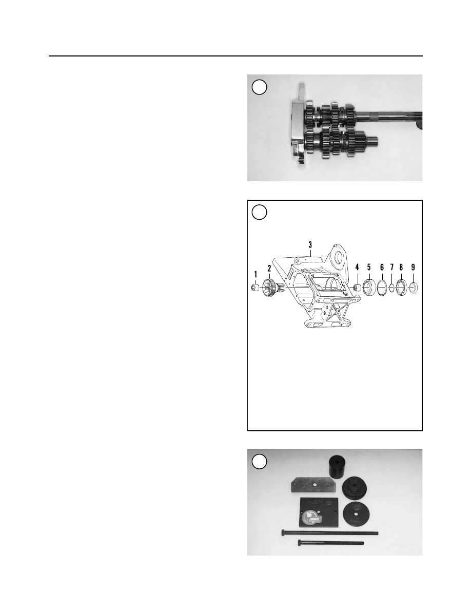
gear where applicable. Make sure the gears are correctly
assembled before installing the shaft assemblies into the
transmission case.
MAIN DRIVE GEAR
The main drive gear (Figure 97) and bearing assembly
are pressed into the transmission case. If the transmission
case is installed in the frame, a special transmission main
drive gear tool set (JIMS part No. 35316-80) (Figure 98)
is required to remove the main drive gear. If the transmis-
sion has been removed, use a press to remove and install
the main drive gear.
Whenever the main drive gear is removed, the main
drive gear bearing must be replaced at the same time.
Removal
1. Remove the transmission shaft assemblies from the
transmission case as described in this chapter.
2. Remove the spacer from the main drive gear oil seal.
3. Remove the circlip behind the bearing.
NOTE
If the main drive gear will not loosen from
the bearing in Step 4 due to corrosion, re-
move the special tools and heat the bearing
with a heat gun.
4. Assemble the special tool set onto the main drive gear
following the manufacturer’s instructions. Then tighten
the puller nut slowly to pull the main drive gear from the
bearing in the transmission case.
5. Remove the main drive gear bearing from the trans-
mission case as described in this section.
Inspection
1. Clean the main drive gear in solvent and dry it with
compressed air, if available.
2. Check each gear tooth (A, Figure 99) for excessive
wear, burrs, galling and pitting. Check for missing teeth.
3. Check the gear splines (B, Figure 99) for excessive
wear, galling or other damage.
4. Inspect the two main drive gear needle bearings for ex-
cessive wear or damage. Refer to Figure 100 and Figure
101. Insert the mainshaft into the main drive gear to check
bearing wear. If necessary, replace the bearings as de-
scribed in this section.
254
CHAPTER SIX
97
MAIN DRIVE GEAR
1. Bearing
2. Main drive gear
3. Transmission case
4. Bearing
5. Mainshaft bearing—left side
6. Snap ring
7. Quad seal
8. Oil seal
9. Sprocket spacer
98
96