Harley Davidson 2009 Dyna Models. Service manual - page 26
A.11
PACKARD 280 METRI-PACK RELAY AND FUSE
BLOCK CONNECTORS
FUSE BLOCK REPAIR
Removing Socket Terminals
1.
See
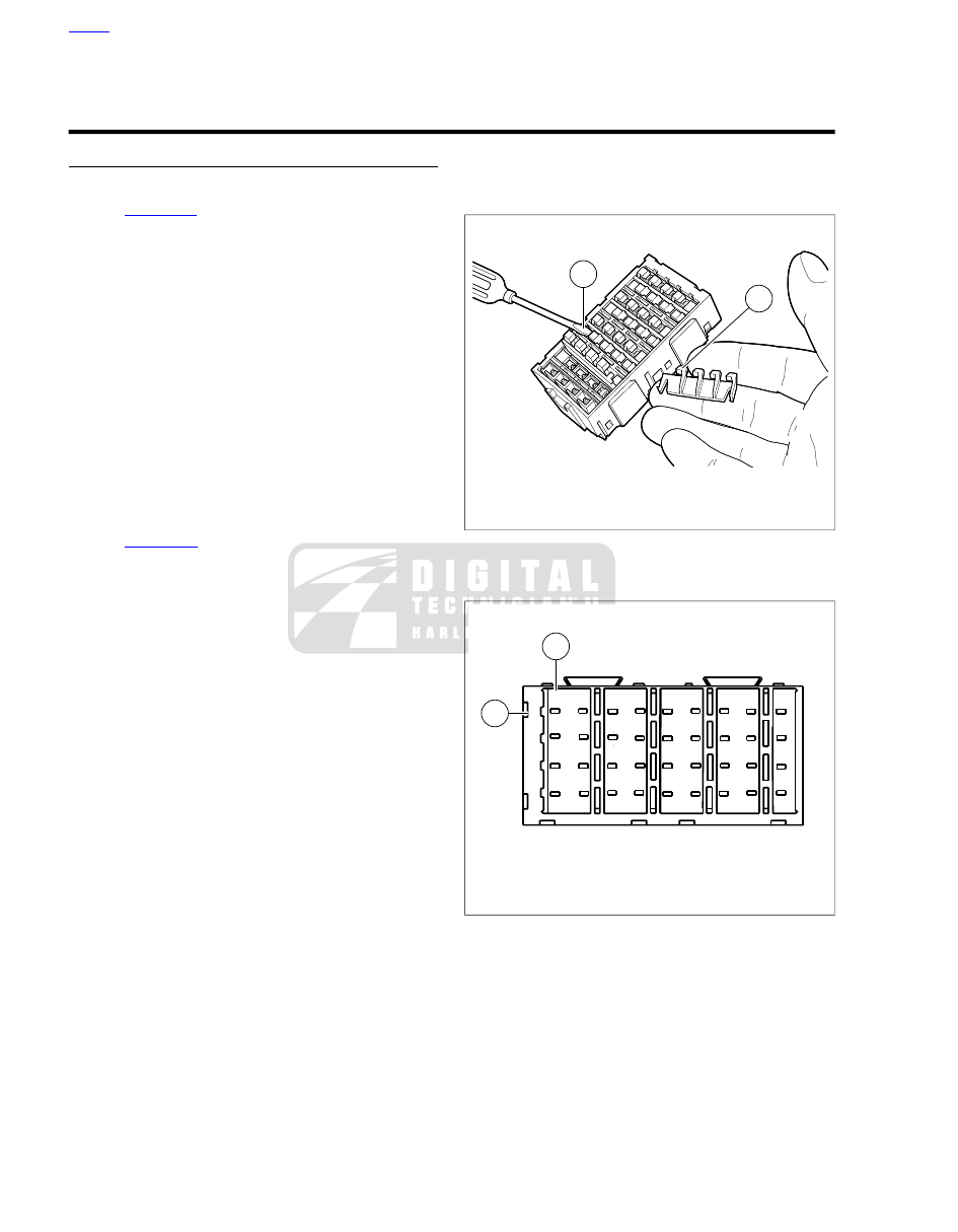
. To remove secondary locks, insert end
of small flat blade screwdriver (1) under lip of locking
wedge (2) and gently pry up secondary lock.
NOTE
For best results, start with locking wedge on outboard side of
secondary lock.
2.
Looking into chamber at top of fuse block, note the tang
next to each socket terminal.
3.
Using a thin flat blade, like that on a hobby knife, gently
push tang away from terminal, and then tug on wire to
back terminal out.
Installing Socket Terminals
1.
Match the wire lead color to the fuse block terminal cavity.
NOTES
•
Refer to the main harness wiring diagram for wire lead
color codes.
•
. The main fuse block terminal cavity is
identified as alpha (1) and numeric (2) coordinates. Refer
to the main harness wiring diagram for fuse block terminal
cavity coordinates.
2.
With the open side of the socket terminal facing the tang,
push lead into chamber at the wire end of the fuse block.
A click is heard when the terminal is properly engaged.
3.
Gently tug on the wire to verify that the terminal is locked
in place and will not back out of the chamber.
4.
Install the secondary locks. With the locking wedges
positioned above the tangs in each chamber, slide flat
side of secondary lock into slot (between rows), and push
down until it bottoms.
Crimping Terminals
Terminals are crimped twice; once over the wire core and a
second time over the insulation/seal.
A correctly crimped terminal may require different crimping
dies found on separate crimpers.
NOTE
The wiring diagram indicates when one socket terminal is be
crimped to two wire leads.
1
2
sm00025
1.
Pry up secondary lock
2.
Lip of locking wedge
Figure A-39. Fuse Block: Remove Secondary Locks
3
A
C
D
E
F
G
H
J
1
2
4
B
1
2
sm00026
1.
Alpha
2.
Numeric
Figure A-40. Fuse Block: Coordinates (typical)
A-24 2009 Dyna Service: Appendix A Connector Repair