Harley Davidson 2009 Dyna Models. Service manual - page 24
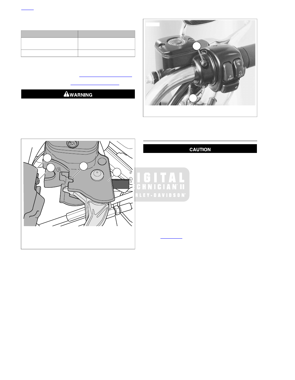
Table 7-13. Handlebar Switch Assembly Fasteners
TORQUE
FASTENER
60-80 in-lbs (6.8-9.0 Nm)
Handlebar switch clamp
screws
35-45 in-lbs (4.0-5.1 Nm)
Switch housing screws
12. Remove the cardboard insert between the brake lever and
lever bracket.
13. Adjust throttle cables. See
14. Install main fuse. See
Be sure that all lights and switches operate properly before
operating motorcycle. Low visibility of rider can result in
death or serious injury. (00316a)
15. Test the switches for proper operation.
16. Secure wire harness to handlebar as necessary.
4
3
2
1
sm01086
1.
Switch housing assembly
2.
Tab
3.
Groove
4.
Brake lever bracket
Figure 7-89. Switch Housing Alignment (typical)
1
2
sm02633
1.
Upper screw
2.
Lower screw and flat washer
Figure 7-90. Handlebar Switch Clamp Screws
DISASSEMBLY
Do not remove or install the master cylinder assembly
without first positioning a 5/32-inch (4 mm) thick insert
between the brake lever and lever bracket. Removing or
installing the master cylinder assembly without the insert
in place may result in damage to the rubber boot and
plunger on the front stoplight switch. (00324a)
1.
Place the cardboard insert between the brake lever and
lever bracket.
2.
Using a T25 TORX drive head, remove the upper and
lower switch housing screws.
3.
If replacing lower housing switches, perform steps 4
through 7 before continuing to repair section. If replacing
upper housing switches, proceed directly to repair section.
4.
See
. Using a T27 TORX drive head, loosen
the upper screw (1) securing the handlebar switch clamp
to the master cylinder housing. Remove the lower clamp
screw with flat washer (2).
5.
Remove the brass ferrules from the notches on the inboard
side of the throttle control grip. Remove the ferrules from
the cable end fittings.
6.
Remove the friction shoe from the end of the tension
adjuster screw.
NOTE
The friction shoe is a loose fit and may fall out or become dis-
lodged if the lower switch housing is turned upside down or
shaken.
7.
Remove the throttle control grip from the end of the
handlebar.
7-68 2009 Dyna Service: Electrical