Harley Davidson 2009 Dyna Models. Service manual - page 22
 

  Главная      Harley Davidson     Harley Davidson 2009 Dyna Models. Service manual


Search            copyright infringement  


Content      ..     20      21      22      23     ..


Harley Davidson 2009 Dyna Models. Service manual - page 22


4.16

FUEL PRESSURE TEST

GENERAL

See 

Figure 4-56

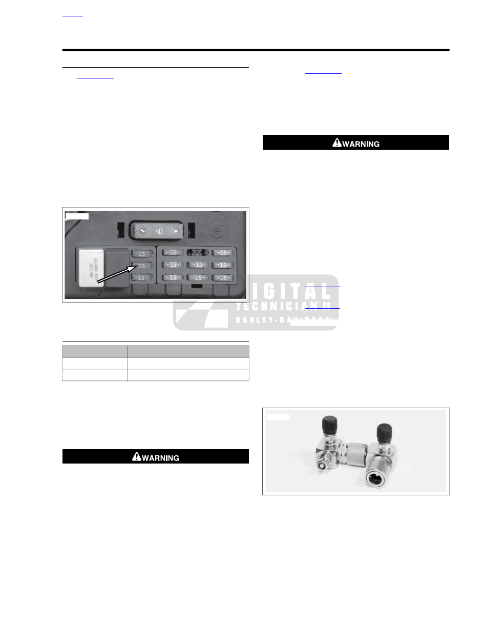
The fuel pump fuse is located in the fuse

block under the left side cover. The fuel pump can be turned
on with Digital Technician or by applying battery voltage to the
fuel pump fuse.

Improper fuel system pressure may contribute to one of the
following conditions:

Cranks, but won't run.

Cuts out (may feel like ignition problem).

Hesitation, loss of power or poor fuel economy.

NOTE

Refer to the electrical diagnostic manual for further information
on the function and testing of the fuel system.

sm02188

Figure 4-56. Fuel Pump Fuse

TESTING

TOOL NAME

PART NUMBER

FUEL PRESSURE GAUGE

HD-41182

FUEL PRESSURE GAUGE ADAPTER

HD-44061

The fuel pressure gauge (0-100 PSI) allows for fuel injector
and fuel system pressure diagnosis. A special adapter allows
the gauge to be attached to the external fuel supply line.

Avoid kinking the fuel line when installing/removing fuel pres-
sure gauge and adapter.

1.

Remove electrical caddy cover.

To prevent spray of fuel, purge system of high-pressure
fuel before supply line is disconnected. Gasoline is
extremely flammable and highly explosive, which could
result in death or serious injury. (00275a)

2.

Purge the fuel supply line of high pressure gas.

a.

See 

Figure 4-56

. Remove the fuel pump fuse from

fuse block.

b.

Start the engine and allow the vehicle to run.

c.

When the engine stalls, operate the starter for 3
seconds to remove any remaining fuel from the fuel
lines.

Gasoline can drain from quick-connect fitting when
removing fuel line. Gasoline is extremely flammable and
highly explosive, which could result in death or serious
injury. Wipe up spilled fuel immediately and dispose of
rags in a suitable manner. (00267a)

3.

Pull up on chrome sleeve of quick-connect fitting (fitting
on left side of fuel tank) and pull down on fuel supply line
to disconnect.

NOTE

The next step requires two fuel pressure gauge adapters.
Failure to use two adapters will cause the fuel line to twist. This
may result in a damaged fuel line or fuel line fitting.

4.

Attach fuel line to gauge assembly.

a.

See 

Figure 4-57

. Install a second adapter in series

with the first.

b.

See 

Figure 4-58

. Pull up on chrome sleeve of quick-

connect fitting and insert neck of FUEL PRESSURE
GAUGE ADAPTER (Part No. HD-44061) into fuel
supply line.

c.

While pushing up on bottom of adapter, pull down on
chrome sleeve until it "clicks" into the locked position.
Tug on adapter to be sure that it will not come free.

d.

In the same manner, install neck of second fuel supply
line fitting into quick-connect fitting on fuel tank. Tug
on fuel supply line to be sure that it will not come free.

sm02625

Figure 4-57. Fuel Pressure Gauge Adapters

HOME

2009 Dyna Service:  Fuel System  4-31

1

4

3

5

2

sm02626

1.

Fuel supply line

2.

Adapter to fuel line

3.

Adapter to fuel tank

4.

Pressure adapter Schroeder valve union

5.

Fuel valve (closed position)

Figure 4-58. Fuel Line

sm02627

Figure 4-59. Fuel Pressure Gauge Installed (Typical)

To prevent spray of fuel, be sure quick-connect fittings
are properly mated. Gasoline is extremely flammable and
highly explosive, which could result in death or serious
injury. (00268a)

5.

Verify that the fuel valve and air bleed petcock on the
FUEL PRESSURE GAUGE (Part No. HD-41182) are
closed.

6.

See 

Figure 4-57

. Remove protective cap from free end of

fuel pressure gauge adapter. Connect fuel pressure gauge
to Schroeder valve.

7.

See 

Figure 4-56

. Install fuel pump fuse.

8.

Start and idle engine to pressurize the fuel system. Open
the fuel valve to allow the flow of fuel down the hose of
the pressure gauge.

9.

Position the clear air bleed tube in a suitable container
and open and close the air bleed petcock to purge the
gauge and hose of air. Repeat this step several times until
only solid fuel (without bubbles) flows from the air bleed
tube. Close the petcock.

10. Open and close throttle to change engine speed. Note the

reading of the pressure gauge. Fuel pressure should
remain steady at 55-62 psi (380-425 kPa).

NOTE

If fuel pressure gauge reading is not within specifications, see
electrical diagnostic manual for further diagnosis.

11. Turn the engine off. Position the air bleed tube in a suitable

container. Open the air bleed petcock to relieve the fuel
system pressure and purge the pressure gauge of gas-
oline.

Gasoline can drain from the adapter when gauge is
removed. Gasoline is extremely flammable and highly
explosive, which could result in death or serious injury.
Wipe up spilled fuel immediately and dispose of rags in a
suitable manner. (00254a)

12. Remove fuel pressure gauge from the adapter. Install

protective cap over Schroeder valve.

Gasoline can drain from the fuel line and adapter when
removed. Gasoline is extremely flammable and highly
explosive, which could result in death or serious injury.
Wipe up spilled fuel immediately and dispose of rags in a
suitable manner. (00255a)

13. Pull up on sleeve of quick-connect fitting and remove fuel

supply line from fuel pressure gauge adapter. Release
adapter from fuel tank in the same manner.

To prevent spray of fuel, be sure quick-connect fittings
are properly mated. Gasoline is extremely flammable and
highly explosive, which could result in death or serious
injury. (00268a)

14. Pull up on chrome sleeve of quick-connect fitting (forward

fitting on left side of tank) and insert neck of fuel supply
line fitting. While pushing up on bottom of fuel supply line
fitting, pull down on chrome sleeve until it "clicks" into the
locked position. Tug on fuel supply line to be sure that it
will not come free.

15. Install electrical caddy cover.

HOME

4-32  2009 Dyna Service:  Fuel System

7.18

ALTERNATOR AND STATOR

REMOVAL

To prevent accidental vehicle start-up, which could cause
death or serious injury, disconnect negative (-) battery
cable before proceeding. (00048a)

1.

Disconnect negative battery cable.

2.

Remove primary cover, primary drive and clutch. See

5.4 DRIVE COMPONENTS

.

3.

Remove primary chaincase housing. See 

5.5 PRIMARY

CHAINCASE HOUSING

.

4.

Disconnect stator connector from voltage regulator. See

7.6 VOLTAGE REGULATOR

.

5.

See 

Figure 7-43

. Remove alternator rotor (4). Two bolts

can be inserted through the holes in the rotor face to aid
during removal.

NOTE

See 

Figure 7-43

. Contact cleaner, alcohol or glass cleaner

sprayed on rubber grommet (3) will provide lubrication when
pulling it through crankcase hole.

6.

Move grommet (3) to one side and spray lubricant into
gap to lubricate grommet and ease removal. Repeat for
other side.

7.

Remove T27 TORX screws (2).

8.

Remove stator (1) while pulling rubber grommet (3) and
wires through crankcase hole.

5

4

3

2

1

sm02552

1.

Stator

2.

T27 TORX screw

3.

Grommet

4.

Rotor

5.

Connector [47B]

Figure 7-43. Rotor and Stator

INSTALLATION

NOTE

Stator Torx fasteners are not re-usable. They must be replaced.

1.

Insert wires through crankcase hole.

2.

See 

Figure 7-43

. Push rubber grommet (3) with wires

through crankcase hole. If necessary, apply the same
lubricant used during removal.

3.

Install the stator (1) on the crankcase and fasten in place
using new TORX screws. Tighten to 55-75 in-lbs (6.2-8.4
Nm).

4.

Mate connector [47] (5) onto voltage regulator and engage
latch to secure. See 

7.6 VOLTAGE REGULATOR

.

5.

Install rotor (4) on the sprocket shaft.

6.

Install primary chaincase housing. See 

5.5 PRIMARY

CHAINCASE HOUSING

.

7.

Install clutch, primary drive and primary cover. See

5.4 DRIVE COMPONENTS

.

8.

Connect negative battery cable.

HOME

7-38  2009 Dyna Service:  Electrical

7.19

FUEL GAUGE

GENERAL

For FXDC, FXDL, FXDB, and FXDF models, the fuel
gauge is mounted in a simulated left fuel tank cap. Remove
by gently pulling upward. Do not twist.

For FXD models, the fuel gauge is in the center console.
See 

7.19 FUEL GAUGE, FXD Models

 which follows for

replacement instructions.

If gauge is to be replaced, remove wires from back of
gauge (FXDC, FXDL, FXDB, and FXDF models).

The fuel gauge sending unit is in the fuel tank under a
console and top plate.

ALL BUT FXD MODELS

Removal

NOTE

The gauge wires are routed through a tube in the tank and are
secured by a cable tie located in the top frame tube underneath
the fuel tank.

Stop the engine when refueling or servicing the fuel
system. Do not smoke or allow open flame or sparks near
gasoline. Gasoline is extremely flammable and highly
explosive, which could result in death or serious injury.
(00002a)

To prevent accidental vehicle start-up, which could cause
death or serious injury, disconnect negative (-) battery
cable before proceeding. (00048a)

1.

Disconnect negative battery cable.

2.

Loosen fuel tank to gain access to the fuel gauge con-
nector. See 

4.6 FUEL TANK

.

3.

Disconnect fuel gauge connector [117] located under left
side of fuel tank.

4.

Detach terminals from connector (4).

NOTE

Do not twist gauge and wiring during removal.

5.

See 

Figure 7-44

. Pull up on gauge (1). Remove gauge,

gasket (2) and wiring from fuel tank. Discard gasket.

4

3

2

1

sm02569

1.

Gauge

2.

Gasket

3.

Wiring harness

4.

Connector [117]

Figure 7-44. Fuel Gauge: All but FXD

Installation

1.

See 

Figure 7-44

. Install wiring harness (3) through new

gasket (2).

2.

Push wiring harness through tube in fuel tank.

3.

While gently pulling on wiring harness, install gauge (1)
and gasket by carefully moving gauge back and forth while
pushing down at the same time.

4.

Install wiring into connector (4) [117]. Mate connector
halves.

5.

Secure wire under fuel tank with new cable tie.

6.

Slide fuel tank into position and install fasteners. See

4.6 FUEL TANK

.

7.

Connect negative battery cable.

FXD MODELS

Console Removal

1.

See 

Figure 7-45

. Remove eight screws (12) that secure

fuel cap trim ring (13) and top plate (3).

2.

Remove screw (10) securing console (14) to fuel tank.

HOME

2009 Dyna Service:  Electrical  7-39

15

16

17

18

19

1

2

3

4

6

5

7

14

13

8

9

10

11

12

sm02570

11. Screw

1.

Gasket

2.

12.

Fuel pump sending unit harness

Screws (8)

13.

3.

Fuel cap trim ring

Top plate

4.

14.

Screws (12)

Console

15.

5.

Trim ring

Fuel gauge: FXD/FXDC

6.

16.

Gasket

Filler cap

17.

7.

O-ring

Connector [117]

8.

18.

Trim

Fuel restrictor

19.

9.

Screw

Mounting ring

10. Screw

HOME

7-40  2009 Dyna Service:  Electrical

Figure 7-45. Fuel Gauge: FXD

Gauge Removal

To prevent accidental vehicle start-up, which could cause
death or serious injury, disconnect negative (-) battery
cable before proceeding. (00048a)

1.

Disconnect negative battery cable.

Stop the engine when refueling or servicing the fuel
system. Do not smoke or allow open flame or sparks near
gasoline. Gasoline is extremely flammable and highly
explosive, which could result in death or serious injury.
(00002a)

2.

Loosen fuel tank to gain access to the fuel gauge con-
nector. See 

4.6 FUEL TANK

.

3.

Disconnect fuel gauge connector [117] located under left
side of fuel tank.

4.

See 

Figure 7-46

. Remove fuel gauge (1) from top plate

(9).

Gauge Installation

1.

See 

Figure 7-46

. Install fuel gauge (1) into top plate (9).

2.

Route fuel gauge wiring (2) as shown.

3.

Connect fuel gauge connector [117] located under left side
of fuel tank.

9

1

2

3

8

7

6

5

4

sm02571

1.

Fuel gauge

2.

Fuel gauge wiring

3.

Fuel pump/sending unit wiring

4.

Filler cap

5.

Fuel cap trim ring

6.

Vent hose

7.

Vent

8.

Fuel pump/sending unit connector [141]

9.

Top plate

Figure 7-46. Top Plate: FXD

Console Installation

1.

See 

Figure 7-46

. If removed, install trim ring (5) so holes

in fuel cap trim ring align with threaded towers of top plate.

2.

See 

Figure 7-45

. Install console (14) over top plate (3).

3.

See 

Figure 7-47

. In next step, be sure slot (2) of fuel cap

trim ring (1) is installed over tab (3) of console (4).

HOME

2009 Dyna Service:  Electrical  7-41

4.

See 

Figure 7-45

. Loosely install eight screws (12) that

hold fuel cap trim ring (13) to top plate (3). Tighten screws
to 18-22 in-lbs (2.03-2.49 Nm).

5.

Install screw (10) securing console to fuel tank. Tighten
screw to 18-24 in-lbs (2.0-2.7 Nm).

4

3

2

1

sm02572

1.

Fuel cap trim ring

2.

Slot

3.

Tab

4.

Console

Figure 7-47. Fuel Cap Trim Ring: FXD

HOME

7-42  2009 Dyna Service:  Electrical

7.20

FUEL GAUGE SENDER

REMOVAL

Stop the engine when refueling or servicing the fuel
system. Do not smoke or allow open flame or sparks near
gasoline. Gasoline is extremely flammable and highly
explosive, which could result in death or serious injury.
(00002a)

To prevent accidental vehicle start-up, which could cause
death or serious injury, disconnect negative (-) battery
cable before proceeding. (00048a)

1.

Disconnect negative battery cable.

2.

Drain fuel into adequately sized, approved gasoline con-
tainer.

3.

Remove instrument console.

a.

For FXDC, FXDF models, see 

7.21 INSTRUMENTS:

FXDC/FXDF

.

b.

For FXDL, FXDB models, see 

7.22 INSTRUMENTS:

FXDB/FXDL

c.

For FXD models, see 

7.19 FUEL GAUGE

.

4.

Disconnect console wiring.

5.

See 

Figure 7-49

. Unplug fuel pump and sender connector

(1) [141].

6.

Remove vent hose (3).

7.

Remove top plate screws (2) and discard.

3

1

2

sm02189

1.

Fuel gauge connector [117]

2.

Clamp

3.

Crossover hose

Figure 7-48. Fuel Gauge Connector and Crossover Hose

1

3

2

sm02192

1.

Fuel pump and sender connector [141]

2.

Screws (12)

3.

Vent hose

Figure 7-49. Top Plate Screws (Typical)

8.

See 

Figure 7-50

. On FXDC, FXDL, FXDB, and FXDF

models, rotate top plate (3) until vent tube (1) clears fuel
tank.

9.

See 

Figure 7-51

. Depress tab and remove fuel

pump/sender wiring from top plate. Remove top plate.

10. Disconnect wire harness from fuel pump.

11. See 

Figure 7-52

. Pull removal tab (2) towards rear of

vehicle to disengage sender (1) from mounting tabs.

NOTE

Be careful not to bend float arm while removing. A bent float
arm will give inaccurate readings.

12. Remove fuel gauge sender from fuel tank.

1

2

3

sm02193

1.

Vent tube

2.

Gasket

3.

Top plate

Figure 7-50. Fuel Line Clamp

HOME

2009 Dyna Service:  Electrical  7-43

sm02194

Figure 7-51. Connector Tab

1

3

2

sm02195a

1.

Fuel gauge sender

2.

Removal tab

3.

Connector

Figure 7-52. Fuel Gauge Sender

INSTALLATION

1.

See 

Figure 7-52

. Install fuel gauge sender (1), making

sure that removal tab (2) is locked in place.

2.

Attach connector (3) to wiring harness.

NOTE

Do not apply any type of sealant to gasket.

3.

See 

Figure 7-53

. Place new gasket (2) under top plate.

Align gasket with screw holes.

4.

Install fuel pump/sender wire connector (4) on top plate
(3).

5.

On FXDC, FXDL, FXDB, and FXDF models, hold top plate
at 90° angle. Making sure that vent tube is installed inside
of tank, rotate top plate into position.

6.

Loosely install new sealing screws in top plate.

NOTE

While the top plate is shaped slightly different for some models,
the torque sequence is identical for all models.

7.

All but FXD: see 

Figure 7-55

Tighten sealing fasteners

using pattern shown to 27-33 in-lbs (3.1-3.7 Nm).

8.

FXD only: see 

Figure 7-55

. Tighten sealing fasteners

using pattern shown to 15-21 in-lbs (1.7-2.4 Nm).

9.

See 

Figure 7-54

. Connect fuel pump/sending unit con-

nector [141].

10. Install instrument console.

a.

For FXDC, FXDF models, see 

7.21 INSTRUMENTS:

FXDC/FXDF

.

b.

For FXDL, FXDB models, see 

7.22 INSTRUMENTS:

FXDB/FXDL

c.

For FXD models, see 

7.19 FUEL GAUGE

.

NOTE

In next step, be sure crimped end of clamp faces toward front
of vehicle.

11. Connect fuel tank crossover hose with new clamps.

12. Connect negative battery cable.

13. Fill tank with gasoline and check for leaks.

5

2

3

4

1

sm02573

1.

Vent tube

2.

Gasket

3.

Top plate

4.

Fuel pump/sender wire connector

5.

Fuel pump harness

Figure 7-53. Top Plate

HOME

7-44  2009 Dyna Service:  Electrical

1

3

2

sm02192

1.

Fuel pump and sender connector [141]

2.

Screws (12)

3.

Vent hose

Figure 7-54. Top Plate Screws (Typical)

9

6

8

11

7

5

12

10

1

3

2

4

sm02196

Figure 7-55. Top Plate Torque Sequence (Typical)

HOME

2009 Dyna Service:  Electrical  7-45

7.21

INSTRUMENTS: FXDC/FXDF

REMOVAL

Speedometer

1.

See 

Figure 7-56

. Remove screw (4) securing trim to fuel

tank. Remove screws (5) securing console to top plate.

2.

Position clean towel on fuel tank and flip console over to
expose underside.

3.

Depress connector tab and disconnect 12-place harness
connector [39] from speedometer (8) under console.

4.

Unscrew the rubber boot (11) from the odometer reset
switch (10) on the left side of the console.

5.

Remove the odometer reset switch from hole in console.

6.

Pry between three tabs and speedometer with a screw-
driver to raise and release back clamp (13) from speedo-
meter. Remove back clamp from speedometer.

7.

Remove speedometer from console (12).

8.

Remove gasket (7) from speedometer.

INSTALLATION

Speedometer

1.

See 

Figure 7-56

. Install gasket (7) to speedometer (8).

2.

Position speedometer in console (12).

3.

Press on back clamp (13) until three tabs engage on back
of speedometer.

4.

Insert odometer reset switch (10) through hole in console
and install rubber boot (11).

5.

Connect 12-place connector [39] to speedometer under
console.

6.

Install console to fuel tank with screws (5). Tighten to
18-24 in-lbs (2.0-2.7 Nm).

7.

Install screw (4) securing fuel tank trim (3) to fuel tank.
Tighten to 18-24 in-lbs (2.03-2.71 Nm).

8.

Test speedometer for proper operation.

15

14

13

12

11

10

9

1

2

3

4

5

6

7

8

sm02575

1.

Push nut

2.

Speed nut

3.

Trim

4.

Screw

5.

Screw

6.

Name plate

7.

Gasket

8.

Speedometer

9.

Bezel

10. Reset switch
11. Boot
12. Console
13. Back clamp
14. Lamp housing
15. Console trim

Figure 7-56. Speedometer: FXDC/FXDF

HOME

7-46  2009 Dyna Service:  Electrical

7.22

INSTRUMENTS: FXDB/FXDL

REMOVAL

General

It is not necessary to cut any of the wiring harness cable ties
to replace the speedometer and tachometer.

Speedometer

1.

See 

Figure 7-57

. Remove screws (5, 6) and lift console

from fuel tank.

2.

Position clean towel on fuel tank and flip console over to
expose underside.

3.

Remove screws (1) and back clamp (2 or 15).

4.

Depress connector tab and remove speedometer con-
nector [39] (11) from back of speedometer (10).

5.

Remove speedometer from console. Remove gasket (7)
from speedometer/console.

Tachometer: FXDL Only

1.

Complete steps 1-3 of speedometer removal.

2.

Depress connector tab and remove tachometer connector
[108] (8) from back of tachometer.

3.

Remove tachometer from console. Remove gasket (7)
from tachometer/console.

INSTALLATION

General

To ease installation, alcohol or glass cleaner may be applied
to the gasket.

Speedometer

1.

See 

Figure 7-57

. Install gasket (7) to console (13 or 14).

2.

Install speedometer (10) in console.

3.

Install speedometer connector [39] (11) to back of
speedometer.

4.

Install back clamp (2 or 15) to speedometer with screws
(1). Make sure there is no binding with the wiring har-
nesses and the bracket.

5.

Install console to fuel tank with screws (5, 6). Tighten to
18-24 in-lbs (2.0-2.7 Nm).

6.

Test speedometer for proper operation.

Tachometer: FXDL Only

1.

See 

Figure 7-57

. Install gasket (7) to console (13).

2.

Install tachometer (9) in console.

3.

Install tachometer connector [108] (8) to tachometer under
console.

4.

Install back clamp (2) to speedometer/tachometer with
screws (1). Make sure there is no binding with the wiring
harnesses and the bracket.

5.

Install console to fuel tank with screws (5, 6). Tighten to
18-24 in-lbs (2.0-2.7 Nm).

6.

Test tachometer for proper operation.

HOME

2009 Dyna Service:  Electrical  7-47

3

3

13

14

12

12

7

7

11

11

10

10

4

4

3

5

3

5

6

6

7

8

9

2

15

1

1

sm02576

9.

1.

Tachometer

Screw

2.

10.

Back clamp: FXDL

Speedometer

11.

3.

Speedometer connector [39]

Speed nut

4.

12.

Console trim

Boot

13.

5.

Console: FXDL

Screw

6.

14.

Screw (2)

Console: FXDB

15.

7.

Back clamp: FXDB

Gasket

8.

Tachometer connector [108]

Figure 7-57. Instrumentation: FXDL, FXDB

HOME

7-48  2009 Dyna Service:  Electrical

7.23

INSTRUMENTS: FXD

REMOVAL

1.

See 

Figure 7-58

. Remove two screws (8) and backplate

(7).

2.

Depress tab and remove 12-pin connector (2) [39] from
back of speedometer.

3.

Push speedometer (1) through front of housing (5).

4.

Remove front gasket (3) from speedometer.

INSTALLATION

NOTE

To ease installation, glass cleaner or alcohol may be applied
to the inside surface of the gasket.

1.

See 

Figure 7-58

. Install front gasket (3) to speedometer

and slide speedometer into housing. Press firmly until fully
seated.

2.

Connect 12-place connector (2) [39] to back of speedo-
meter.

3.

Route wires through slot in back of instrument housing.
Install rear gasket (6) on back of housing. Install backplate
(7) with two screws (8).

8

9

10

1

2

3

4

5

6

7

sm02577

6.

1.

Rear gasket

Speedometer

2.

7.

Connector [39]

Backplate

8.

3.

Screw

Front gasket

4.

9.

Bolt @ 12-18 ft-lbs (16.3-24.4 Nm)

LED assembly

10.

5.

Connector [20]

Housing

Figure 7-58. Instrumentation: FXD

HOME

2009 Dyna Service:  Electrical  7-49

7.24

VEHICLE SPEED SENSOR (VSS)

GENERAL

The vehicle speed sensor is a Hall Effect sensor that takes
readings off 4th gear in the transmission.

The vehicle speed sensor is located on the transmission just
behind the transmission top cover.

REMOVAL

1.

Disconnect battery, negative cable first.

2.

See 

Figure 7-59

. Disconnect the vehicle speed sensor

connector [65].

3.

Remove sensor mounting bolt and lift sensor from trans-
mission case.

NOTE

Before removing sensor wire, carefully note wire routing. It is
a good idea to lay the new sensor wire next to the old wire and
remove and replace the wires together, one cable strap at a
time, to ensure proper routing.

INSTALLATION

1.

See 

Figure 7-59

. Install sensor into transmission case

using mounting bolt. Tighten bolt to 84-108 in-lbs (9.5-
12.2 Nm).

2.

Install connector [65] to speed sensor.

3.

Connect battery cables.

After installing seat, pull upward on seat to be sure it is
locked in position. While riding, a loose seat can shift
causing loss of control, which could result in death or
serious injury. (00070b)

4.

Install seat.

sm02215

Figure 7-59. Vehicle Speed Sensor and Connector [65]

HOME

7-50  2009 Dyna Service:  Electrical

7.25

INDICATOR LAMPS

GENERAL

Dyna models are equipped with Light Emitting Diode (LED)
indicators. The indicator LED assembly is not serviceable. If
one LED is bad, the entire assembly must be replaced.

REMOVAL

FXDC/FXDF Models

1.

See 

Figure 7-60

. Remove screws (1) and raise console

(2) from fuel tank. Place shop rags on tank and flip console
over to expose underside.

2.

See 

Figure 7-61

. Squeeze clips together (2) and gently

pry LED assembly (1) out of console from the side with a
screwdriver.

3.

Disconnect 8-place connector (3) [21] from LED assembly.

2

1

3

sm02578

1.

Screw (2)

2.

Console

3.

LED assembly

Figure 7-60. Indicator Lamp Assembly: FXDC, FXDF

3

1

2

2

sm02579

1.

LED assembly

2.

Clips (2 pair)

3.

Connector [21]

Figure 7-61. FXDC, FXDF Conncector [21]

FXDB Models

1.

See 

Figure 7-62

. Remove long console fasteners (1) and

short console fastener (2).

2.

Raise console (3) from fuel tank. Place shop rags on tank
and flip console over to expose underside.

3.

See 

Figure 7-63

. Release clips (2) to free LED housing

(1) from console.

4.

Disconnect connector (3) [21] from LED assembly.

HOME

2009 Dyna Service:  Electrical  7-51


Content      ..     20      21      22      23     ..