Harley Davidson FLHRC 2006. Maintenance & Repair Manual - page 17

HOME
HARD STARTING
Check for:
Remedy:
1.
Enrichener system plugged, not properly functioning
1.
Clean, adjust, or replace; or read Owner’s Manual.
or improperly operated.
2.
Correct as required.
2.
Inlet system air leak.
3.
Check fuel supply and/or passages. Verify that vacuum
3.
Restricted fuel supply.
operated fuel valve is functional.
4.
Fuel overflow.
4.
See Overflow Troubleshooting.
5.
Plugged slow jet or passages.
5.
Clean and clear jet or passages.
POOR PERFORMANCE ON ROAD
Check for:
Remedy:
1.
Inlet system air leak.
1.
Correct as required.
2.
Restricted fuel tank vent system.
2.
Correct restricted hose. Replace vapor valve.
3.
Dirty or damaged air cleaner element.
3.
Clean or replace.
4.
Accelerator pump inoperative.
4.
Repair as required.
5.
Plugged bowl vent or overflow.
5.
Clean and clear passages.
6.
Vacuum piston assembly malfunction.
6.
See Vacuum Piston Troubleshooting.
7.
Loose or plugged fuel and air jets or passages.
7.
Clean, clear and correct as required.
8.
Worn or damaged needle or needle jet.
8.
Replace assembly.
9.
Restricted fuel supply tract.
9.
Correct and clear restriction.
10. Enrichener valve not seated or leaking.
10. Adjust, clean or replace.
11. Idle speed improperly adjusted.
11. Adjust operating idle speed.
POOR HIGH SPEED PERFORMANCE
Check for:
Remedy:
1.
Inlet system air leak.
1.
Clean or replace.
2.
Restricted fuel tank vent system.
2.
Correct restricted hose. Replace vapor valve.
3.
Dirty or damaged air cleaner element.
3.
Clean or replace.
4.
Accelerator pump inoperative.
4.
Repair as required.
5.
Plugged bowl, vent or overflow.
5.
Clean and clear passages.
6.
Vacuum piston assembly malfunction.
6.
See Vacuum Piston Troubleshooting.
7.
Restricted fuel supply tract.
7.
Correct and clean restriction.
8.
Loose or plugged main jets or passages.
8.
Tighten, clean, clear as required.
9.
Improper fuel level.
9.
Adjust float level.
10. Worn or damaged needle or needle jet.
10. Replace assembly.
11. Enrichener valve not seated or leaking.
11. Adjust, clean or replace.
2006 Touring: Fuel
4-3
HOME
VACUUM PISTON ASSEMBLY TROUBLESHOOTING
PISTON DOES NOT RAISE PROPERLY
Check for:
Remedy:
1.
Diaphragm cap loose, damaged or leaking.
1.
Tighten or replace cap.
2.
Diaphragm pinched at lip groove.
2.
Reposition diaphragm lip.
3.
Piston atmosphere vent blocked.
3.
Clear vent.
4.
Piston vacuum passage plugged.
4.
Clean and clear passage.
5.
Torn diaphragm.
5.
Replace piston diaphragm assembly.
6.
Piston binding.
6.
Clean piston slides and body or replace piston.
7.
Spring binding.
7.
Correct or replace spring.
8.
Enrichener valve open, not seated or leaking.
8.
Adjust, clean or replace.
PISTON DOES NOT CLOSE PROPERLY
Check for:
Remedy:
1.
Piston diaphragm ring dirty or damaged.
1.
Clean or replace piston.
2.
Piston binding.
2.
Clean piston slides and body or replace piston.
3.
Spring damaged.
3.
Replace spring.
4-4
2006 Touring: Fuel
HOME
ENRICHENER (CARBURETED)
4.3
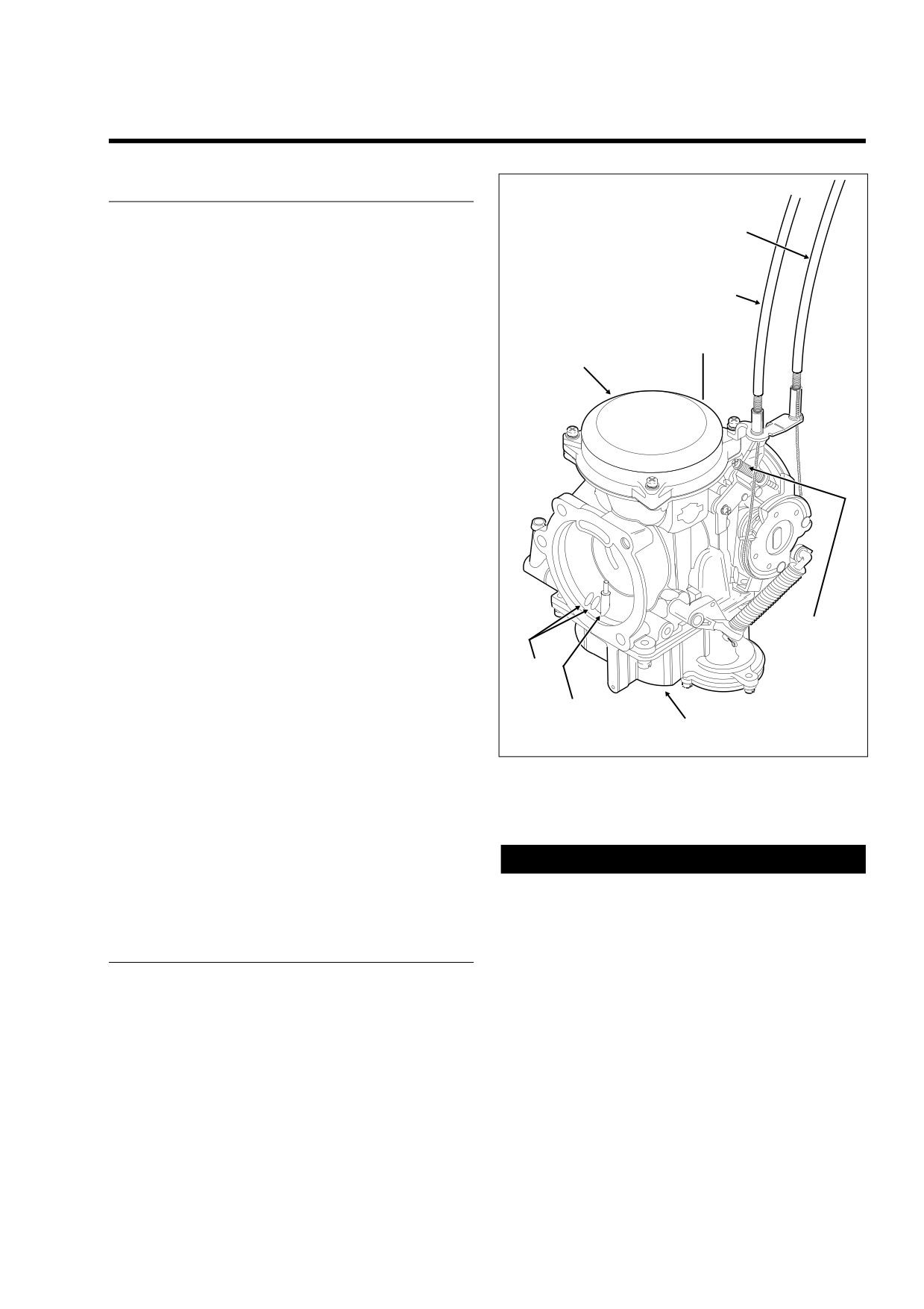
GENERAL
1.
Idle Cable
2.
Throttle Cable
The carburetor is a constant velocity, gravity fed type with a
3.
Vacuum Fitting (At Back)
1
float operated inlet valve, a variable venturi, a throttle stop
4.
Vacuum Piston Chamber
screw for idle speed adjustment and a fuel enrichment sys-
5.
Float Chamber
tem for starting. See Figure 4-1.
6.
Idle Speed Set Screw
7.
Air Jets
2
The fuel enrichment circuit will cause engine idle speed to
8.
Accelerator Pump Nozzle
increase to approximately 2000 rpm with enrichener knob
pulled out fully and engine running at normal operating tem-
3
perature. With enrichener knob pulled out partially and
4
engine running at normal operating temperature, engine idle
speed will also increase above normal idle speed. The
increase in idle speed is intended to alert the rider that
engine is warmed up, and that enrichener knob should be
pushed in all the way. Continued use of enrichener after
engine is warmed up may cause fouled spark plugs.
Idle and transfer ports provide a balanced fuel mixture during
the transition period from stop to mid-range. A vacuum piston
controls venturi opening.
The carburetor is specifically designed to control exhaust
emissions. All jets are fixed. The idle mixture has been pre-
set at the factory.
The idle mixture screw is recessed in the carburetor casting.
The opening is sealed with a plug because it is intended that
6
the idle mixture be non-adjustable.
NOTE
7
Adjusting mixture setting by procedures other than specified
in this section may be in violation of Federal or State regula-
8
tions.
f1381b2x
5
This system partially compensates for changes in the mixture
that are normally caused by changes in altitude. Because
Figure 4-1. CVH Carburetor
atmospheric pressure decreases as altitude increases, the
pressure difference in the upper and lower chambers is
reduced, which provides less fuel to the engine.
The carburetor is equipped with an accelerator pump. The
accelerator pump system uses sudden throttle openings
CAUTION
(rapid accelerations) to quickly inject fuel into carburetor ven-
Never accelerate the engine above 2500 RPM immedi-
turi to provide extra fuel for smooth acceleration.
ately after a cold start. Allow the engine to run slowly for
15-30 seconds. This will allow the engine to warm up and
let oil reach all surfaces needing lubrication. Extended
OPERATION
idling with enrichener in the full out position for a period
longer than 30 seconds is not recommended.
Enrichener
NOTE
The enrichener knob, located under the left side of the fuel
● H-D CV carburetors have an enrichener circuit that will
tank, controls opening and closing of the enrichener circuit in
cause the engine to idle at approximately 2000 rpm with
the carburetor. The enrichener knob can be adjusted to any
the engine at normal operating temperature and the
position, from full-in to full-out.
enrichener knob pulled fully out.
2006 Touring: Fuel
4-5
HOME
● The increase in idle speed is intended to alert the rider
that the engine is warmed up to normal operating tem-
f1808x4x
perature and the enrichener knob should be pushed all
the way in.
● Continuing to use the enrichener when the engine is at
full operating temperature WILL CAUSE FOULED
3
SPARK PLUGS.
2
CAUTION
1
Pay close attention to the vehicle's warm-up time. Either
excessive or insufficient use of the enrichener may
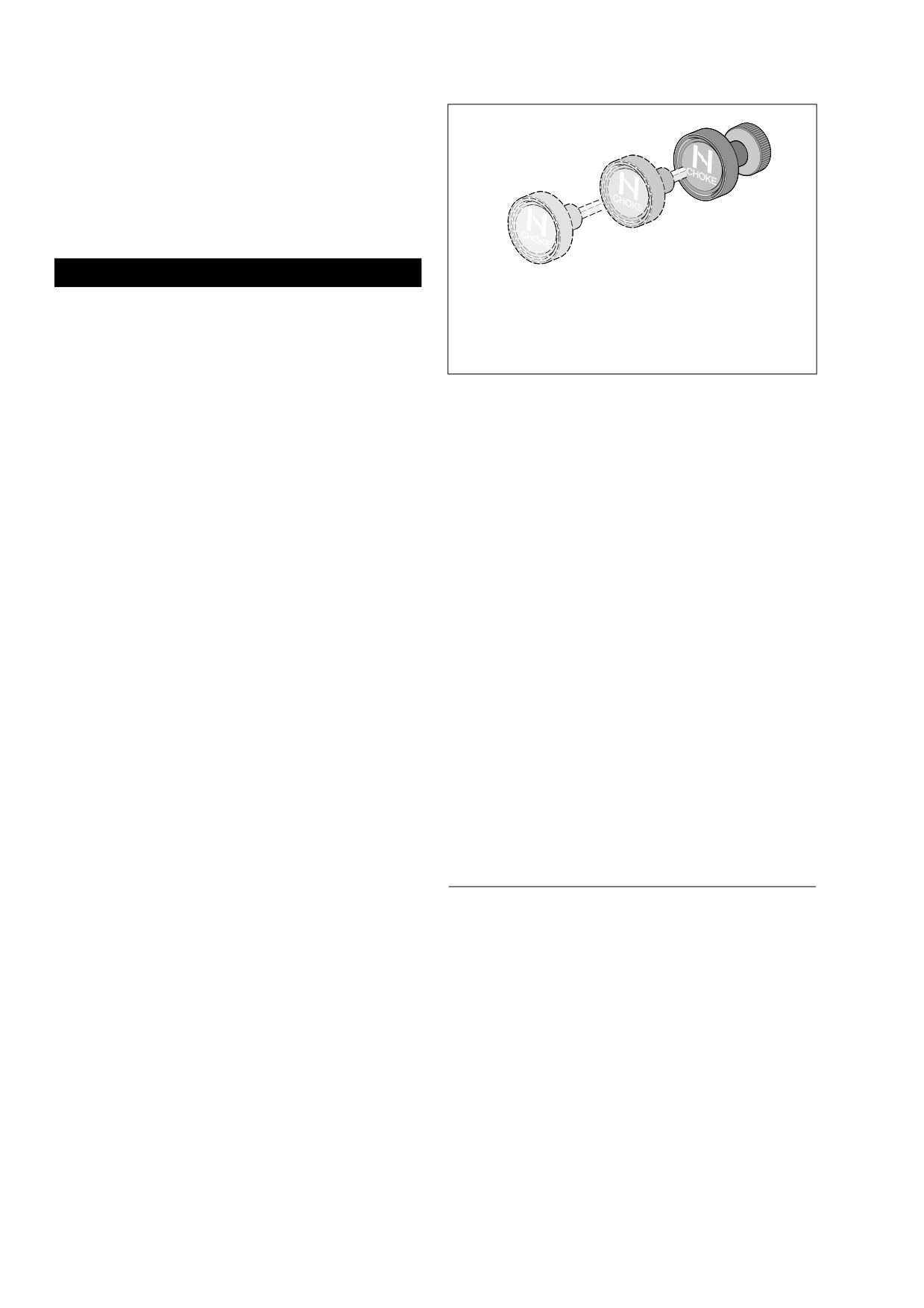
1.
Full-Out (Cold Engine Starts)
cause poor performance, erratic idle, poor fuel economy
2.
1/2-Way Position
and spark plug fouling.
3.
Full-In (Normal Running Position)
NOTE
Figure 4-2. Set the Enrichener Knob
The following starting and operating instructions for all carbu-
reted motorcycles should be viewed as recommendations
only. They may be modified for individual vehicles.
2.
Push the enrichener knob in to the 1/2 way position. Ride
an additional 1 minute or 1/2 mile (0.8 km).
3.
Push the enrichener knob fully in.
Cool Engine
Outside Temperature Cooler than 60˚ F
Warm Climate Or Hot Engine
Turn the fuel valve to the ON position. BE SURE THAT THE
Turn the fuel valve to the ON position. Turn the Ignition/Light
THROTTLE IS CLOSED. Pull the enrichener knob to the “full
Key Switch knob to the IGNITION position. Turn the Engine
out” position. Turn the Ignition/Light Key Switch knob to the
Stop Switch to the RUN position. Open throttle 1/8 - 1/4 turn.
IGNITION position. Turn the Engine Stop Switch to the RUN
Press the Engine Start Switch to operate the electric starter.
position. Press the Engine Start Switch to operate the electric
DO NOT USE ENRICHENER.
starter.
NOTE
1.
After initial 15-30 second warm-up, ride for 3 minutes or
2 miles (3.2 km) with enrichener knob in full out position.
If the engine does not start after a few turns or if one cylinder
See Figure 4-2.
fires weakly but engine does not start, it is usually because of
an over-rich (flooded) condition. This is especially true of a
2.
Push the enrichener knob in to the 1/2 way position. Ride
hot engine. If the engine is flooded, push enrichener knob in
an additional 2 minutes or 2 miles (3.2 km).
all the way, turn ignition on and operate starter with throttle
wide open. DO NOT "pump" the throttle while turning over the
3.
Push the enrichener knob fully in.
engine.
NOTE
If outside temperature is cooler than 20˚ F it may be neces-
sary to pump the throttle control grip 2 or 3 times.
ADJUSTMENTS
Outside Temperature Warmer than 60˚ F
Slow Idle
Turn the fuel valve to the ON position. BE SURE THAT THE
NOTE
THROTTLE IS CLOSED. Pull the enrichener knob to the “full
out” position. Turn the Ignition/Light Key Switch knob to the
Make certain enrichener knob is pushed all the way in before
IGNITION position. Turn the Engine Stop Switch to the RUN
adjusting engine idle. The CV carburetor enrichener-circuit
position. Press the Engine Start Switch to operate the electric
will cause the engine idle speed to increase to between 1500
starter.
and 2000 rpm with the enrichener knob pulled out fully and
the engine at normal operating temperature.
(With the
1.
After the initial 15-30 second warm-up, ride for 1 minute
enrichener knob pulled out partially and normal engine oper-
or 1/2 mile (0.8 km) with enrichener knob in full out posi-
ating temperature, the engine idle speed will increase above
tion. See Figure 4-2.
normal idle speed (950-1050 rpm) to approximately 2000 rpm
4-6
2006 Touring: Fuel
HOME
maximum with the enrichener knob pulled out fully). The
Enrichener Control
increase in idle speed is intended to alert the rider that the
engine is warmed-up and the enrichener knob should be
The fuel enrichener knob should open, remain open and then
pushed all the way in. Continued use of the enrichener, after
close without binding. The knurled plastic nut next to the
engine is at normal operating temperature, may cause fouled
enrichener knob controls the ease at which the cable slides
spark plugs.
within the conduit. If adjustment is needed, see Section 1.12
ENRICHENER CONTROL.
With the engine at normal operating temperature and the
enrichener all the way in (enrichener valve closed) adjust the
throttle stop screw so the engine idles at 1000 rpm.
NOTE
Use a test tachometer, connected to negative ignition coil ter-
minal to measure engine rpm on models without tachome-
ters.
2006 Touring: Fuel
4-7
HOME
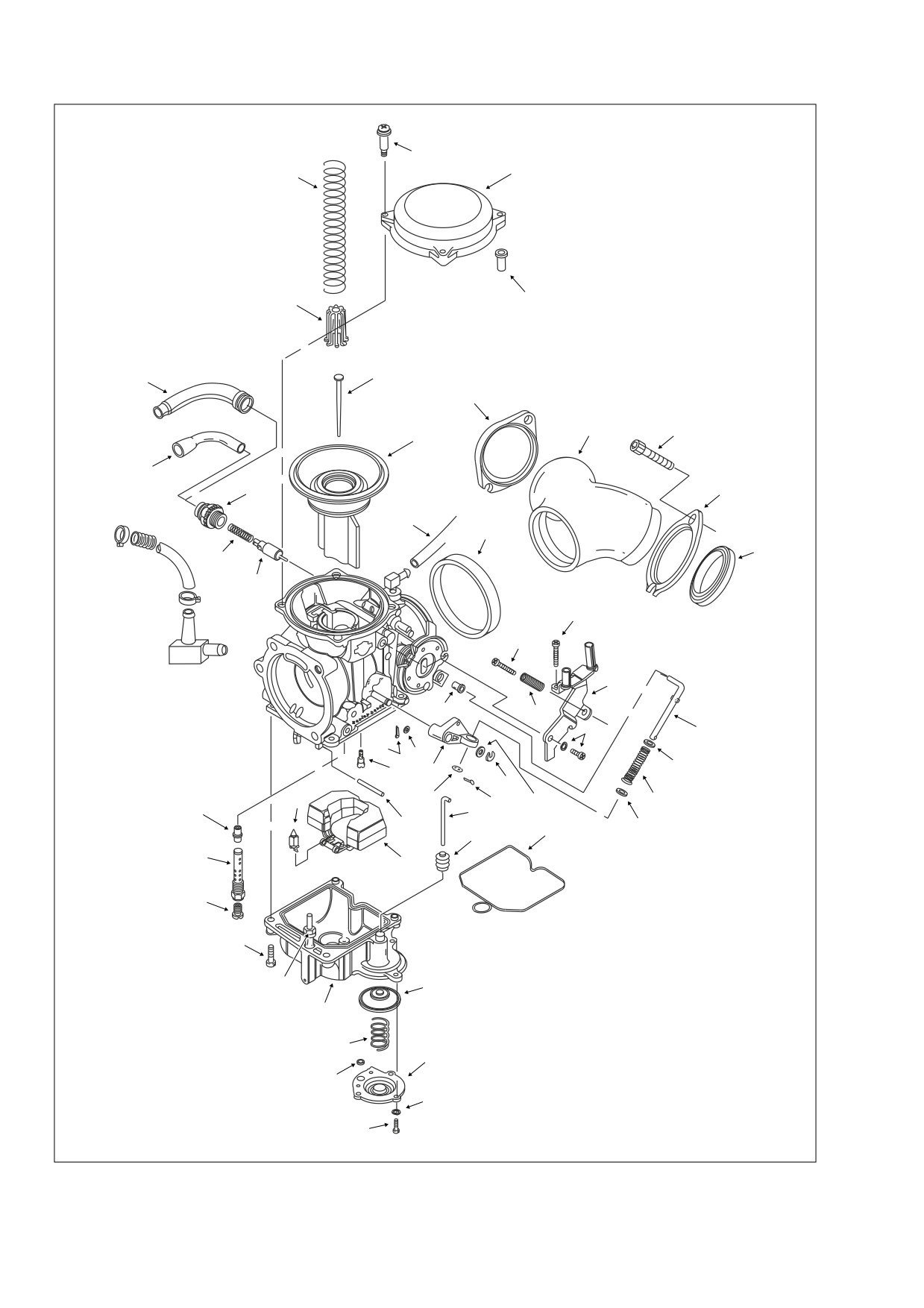
1.
Top
14.
Float
2.
Screw (3)
15.
O-ring
3.
Spring
16.
Screw (4)
2
4.
Vacuum piston
17.
Cable seal boot
5.
Spring seat
1
18.
Cable guide
3
6.
Jet needle
19.
Starter cap
7.
Vacuum hose
20.
Enrichener valve
8.
Needle jet
21.
Spring
9.
Needle jet holder
22.
Throttle cable bracket
10.
Main jet
23.
Bracket screw
11.
Slow jet
24.
Bracket screw and washer
12.
4-sided Fuel valve with clip
25.
Idle speed adjust screw
13.
Pin
26.
Spring
27.
Collar
28.
Seal ring
5
27
29.
Manifold
30.
Flange
31.
Intake manifold seal (2)
32.
Lever
33.
Float bowl
34.
E-clip
6
35.
Accelerator pump nozzle
17
36.
Spring
30
29
46
4
18
19
30
7
28
31
21
20
23
25
22
45
26
24
47
48
51
11
49
32
34
52
12
36
48
50
8
44
13
15
53
43
9
14
37. Pump housing
10
38. Spring
39. Diaphragm
40. O-Ring (2)
16
41. Washer (3)
42. Screw (3)
43. Boot
44. Rod
35
39
45. Collar
46. Screw (4)
33
47. Rod
48. Cotter pin (2)
49. Washer
38
NOTE
37
50. Washer
51. Washer
With the exception of the jet sizes, all
40
52. Washer
53. Washer
FL models are equipped with the
41
same basic carburetor.
42
f2320x4x
Figure 4-3. Carburetor
4-8
2006 Touring: Fuel
HOME
CARBURETOR
4.4
REMOVAL
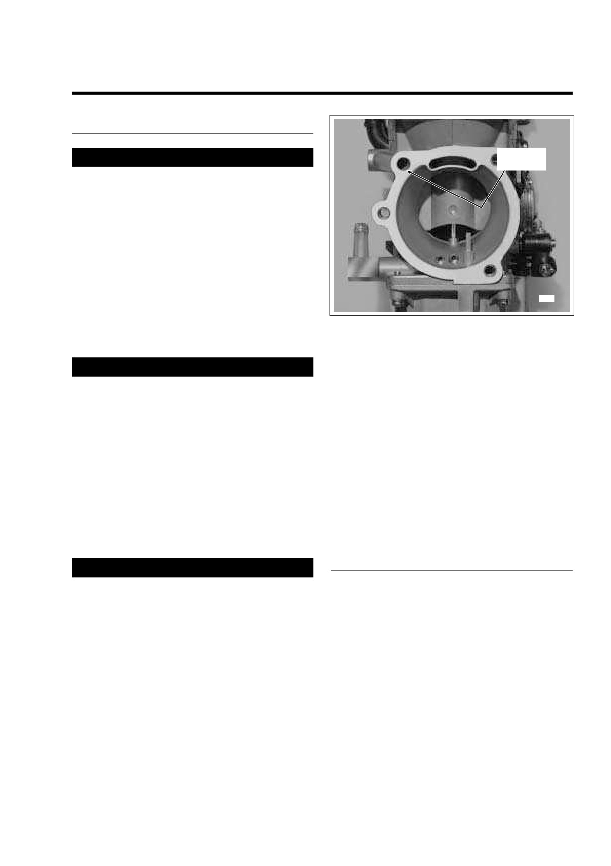
Float Bowl
1WARNING
Vent
Gasoline is extremely flammable and highly explosive.
When servicing the fuel system, do not smoke or allow
open flame or sparks in the vicinity. Inadequate safety
precautions could result in death or serious injury.
1.
Remove maxi-fuse. See Section 8.3 SYSTEM FUSES,
MAXI-FUSE, REMOVAL.
2.
Remove air cleaner assembly. See Section 4.5 AIR
CLEANER, REMOVAL.
3.
Locate the fuel enrichener knob under the left side of the
fuel tank, and loosen hex nut at backside of mounting
8982
bracket. Slide cable assembly free of slot in mounting
bracket.
Figure 4-4. Drain Carburetor Float Bowl
4.
Rotate handle on fuel valve to the horizontal position to
shut the gasoline supply to the carburetor OFF.
1WARNING
8.
Using a needle nose pliers, carefully pull idle cable bar-
rel from upper inboard hole in throttle wheel. Pull throttle
Some gasoline will drain from the fuel inlet hose when
cable barrel from remaining hole. Release idle and throt-
disconnected from the carburetor. Thoroughly wipe up
tle cables from guides in throttle cable bracket.
any spilled fuel immediately. Dispose of rags in a suit-
able manner. Gasoline is extremely flammable and
9.
Pull vacuum hose elbow from fitting on inboard side of
highly explosive. Inadequate safety precautions could
carburetor.
result in death or serious injury.
10.
Carefully remove carburetor while drawing enrichener
5.
Using a side cutters, cut clamp and remove fuel inlet
cable to right side of motorcycle.
hose from fitting at side of carburetor.
11.
Keeping carburetor upright, move assembly to bench
NOTE
area. Tilting carburetor, carefully pour gasoline in float
On California models, pull purge tube from fitting on same
bowl into a suitable container. Gasoline will exit float
side of carburetor.
bowl vent shown in Figure 4-4.
6.
Gently work carburetor free of seal ring on intake mani-
fold.
INSTALLATION
1WARNING
As the carburetor is removed, be sure to keep assembly
1.
Place carburetor into approximate position on right side
upright as the float bowl contains gasoline. Tilting the
of motorcycle while feeding enrichener cable over to left
carburetor or turning it upside down will cause the gaso-
side.
line to drain onto surrounding area. Gasoline is
2.
Push vacuum hose elbow onto fitting on inboard side of
extremely flammable and highly explosive. Inadequate
carburetor.
safety precautions could result in death or serious
injury.
3. Install sleeve on throttle cable housing into shorter cable
guide in throttle cable bracket. Drawing throttle cable
7.
If cruise control equipped, remove E-clip from groove at
downward, fit barrel end into lower outboard hole in
end of cruise cable housing. Remove cruise cable hous-
throttle wheel. Install sleeve and spring on idle cable
ing from cable guide in throttle cable bracket. Push plas-
housing into longer cable guide inserting barrel end into
tic end fitting on cruise cable to outboard side to release
upper inboard hole in throttle wheel.
from wheel pin.
2006 Touring: Fuel
4-9
HOME
10. Install air cleaner assembly. See Section
4.5 AIR
8981
CLEANER, INSTALLATION.
11. Install maxi-fuse. See Section
8.3 SYSTEM FUSES,
MAXI-FUSE, INSTALLATION.
12. Rotate handle of fuel valve clockwise to the vertical posi-
tion and carefully inspect for leaks. Return the valve to
the OFF position when finished.
13. Adust the engine idle speed. See Section
4.3
ENRICHENER (CARBURETED), ADJUSTMENTS.
DISASSEMBLY
Vacuum Piston Chamber
1.
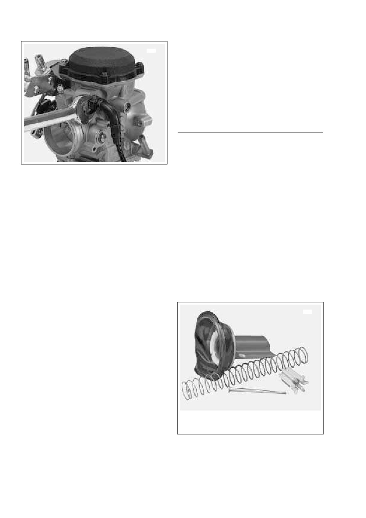
Placing a 14mm open end wrench on hex, loosen plastic
fitting at enrichener bore of carburetor housing. See Fig-
ure 4-5. Rotate enrichener cable in a counterclockwise
Figure 4-5. Remove Enrichener Cable
direction to unthread fitting and remove valve assembly.
2.
Remove gold Phillips screw (with lockwasher) at side of
4.
Verify that cables are fully seated in channel of throttle
carburetor to release throttle cable bracket. Remove gold
wheel, and using cable adjusters at handlebar, tighten
Phillips screw
(with top collar) to free throttle cable
cables as necessary to keep barrel ends from dislodging.
bracket from carburetor top. Set bracket aside.
Verify operation by turning throttle grip and observing
3.
Remove three remaining top screws to release carbure-
cable action.
tor top from body.
5.
If cruise control equipped, slide plastic end fitting over
4.
Remove vacuum piston spring. Carefully raise dia-
cap of wheel pin. Push on end fitting until it snaps in
phragm to remove vacuum piston assembly. Remove
place. Slip cruise cable housing into cable guide in throt-
spring seat and jet needle from vacuum piston bore. See
tle cable bracket. Install new E-clip into groove at end of
Figure 4-6.
cruise cable housing.
NOTE
Float Chamber
The fit between the carburetor and seal ring is tight. Prior to
1.
Turn carburetor upside down and remove four Phillips
assembly, lubricate mating surfaces with liquid dishwashing
screws at bottom to remove float bowl from carburetor
soap or tire mounting lube. Always install new seal ring if
body.
dried out, cracked or otherwise damaged.
6.
Lubricate inside diameter of seal ring. Also apply a light
film of lubricant to carburetor housing where casting
7754
comes into contact with seal ring. Gently work carburetor
into seal ring.
7.
Slide new clamp onto free end of fuel inlet hose. Install
2
hose onto brass fitting at side of carburetor. Making sure
clamp is positioned inboard of lip on fitting, crimp clamp
1
using HOSE CLAMP PLIERS (HD-97087-65B).
NOTE
On California models, push purge tube onto fitting on same
side of carburetor.
8.
Moving to left side of motorcycle, slide threaded portion
of enrichener cable into slot of mounting bracket. Flat on
threads must face rear of motorcycle for script on
4
3
enrichener knob to be right side up. With the external
tooth lockwasher and hex nut positioned on the inboard
side of the mounting bracket, tighten hex nut to 20-35 in-
1.
Spring
3.
Spring Seat
lbs (2.3-4.0 Nm).
2.
Vacuum Piston
4.
Jet Needle
9.
Adjust throttle cables. See Section
2.21 THROTTLE
CABLES (NON-CRUISE), ADJUSTMENT.
Figure 4-6. Vacuum Piston Chamber Components
4-10
2006 Touring: Fuel
HOME
NOTE
Since accelerator pump rod is now loose, remove from hole
7751
A
2
in lever at side of carburetor body.
CAUTION
Tapping the float pin out from the squared pedestal side
will result in damage that requires carburetor replace-
ment
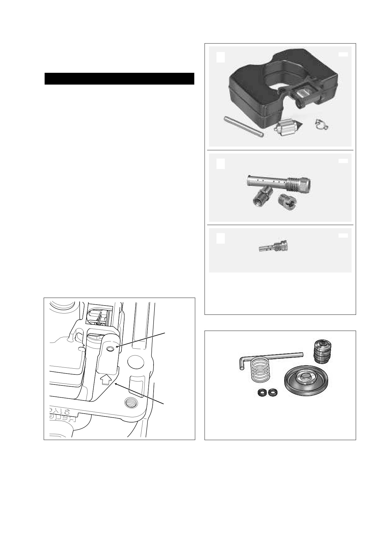
2.
Using a small center punch and hammer, carefully tap
float pin from holes in pedestals. The rounded pedestal
has an interference fit to ensure that the float pin is
1
4
securely held, so always tap out the pin in the direction
3
of the cast-in arrow (that is, from the interference side).
See Figure 4-7.
3.
Remove float and fuel valve. Carefully slide wireform clip
7750
B
on fuel valve from tab on float. Remove wireform clip
6
from groove in fuel valve. See A of Figure 4-8.
4.
Using slot at top, turn main jet with flat tip screwdriver to
unthread from needle jet holder. If necessary, hold hex
on needle jet holder with a 5/16 inch wrench to prevent
rotation. See Figure 4-10.
7
5
5.
Using a 5/16 inch wrench, turn hex on needle jet holder
to unthread from main jet bore.
6.
Turn carburetor right side up to drop out needle jet,
7755
which is loose in main jet bore. See B of Figure 4-8.
C
7.
Insert thin bladed flat tip screwdriver into slow jet bore.
See Figure 4-10. Using slot at top of slow jet, unthread
8
to remove. See C of Figure 4-8.
8.
Disassemble accelerator pump from float bowl. See Fig-
ure 4-9. Proceed as follows:
1.
Float Pin
5.
Main Jet
2.
Float
6.
Needle Jet Holder
3.
Fuel Valve
7.
Needle Jet
4.
Wireform Clip
8.
Slow Jet
Figure 4-8. Float Chamber Components
Float Pin
f1868x4x
1
2
3
4
5
Arrow
1.
Rod
2.
Rubber Boot
4.
Diaphragm
3.
Spring
5.
O-Rings
a0183x4x
Figure 4-7. Remove Float Pin in Direction of Arrow
Figure 4-9. Accelerator Pump Components
2006 Touring: Fuel
4-11
HOME
a. Remove rubber boot from post at top of accelerator
b. Using a tapered, rubber-tipped nozzle on the air
pump upper housing.
hose (to prevent both loss of air pressure and to
avoid scratching or nicking the bore), apply low pres-
b. Turn float bowl upside down. Alternately loosen and
sure compressed air into air inlet hole to blow carbu-
then remove three Phillips screws
(with lock-
retor cleaner out of slow jet bore. Placing gloved
washers) to release accelerator pump lower hous-
finger over slow jet bore, blow carburetor cleaner out
ing.
of pin holes inboard and outboard of throttle plate.
c. Remove spring and diaphragm from accelerator
pump upper housing. Remove two O-rings from
Main Circuit
lower housing.
a. Plugging main jet hole in carburetor throat, spray
carburetor cleaner into air inlet hole of main circuit.
CLEANING AND INSPECTION
See A of Figure 4-11. While spraying, verify that
solution exits main jet bore at bottom of carburetor
housing. See B of Figure 4-11.
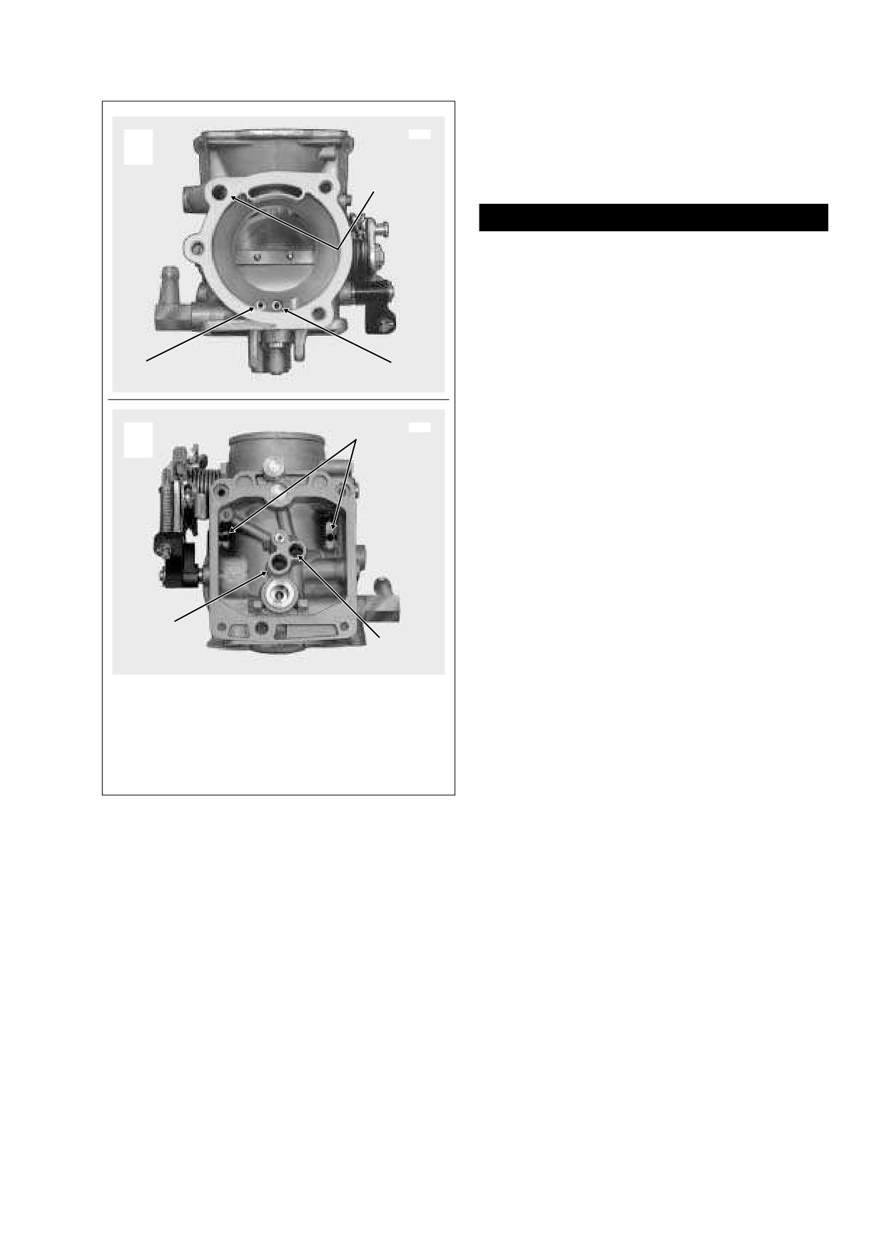
Carburetor Housing
b. Using a tapered, rubber-tipped nozzle on the air
1.
Clean all internal air/fuel passages in carburetor housing
hose (to prevent both loss of air pressure and to
with carburetor cleaner. Blow out passages using low
avoid scratching or nicking the bore), apply low pres-
pressure compressed air. Proceed as follows:
sure compressed air into air inlet hole to blow carbu-
retor cleaner out of hole in carburetor throat. Placing
gloved finger over hole in carburetor throat, blow
1WARNING
carburetor cleaner out of main jet bore at bottom of
Compressed air can pierce the skin and flying debris
carburetor housing.
from compressed air could cause serious eye injury.
Wear safety glasses when working with compressed air.
Float Bowl Vent
Never use your hand to check for air leaks or to deter-
mine air flow rates. (00061a)
a. Spray carburetor cleaner into air inlet hole of float
bowl vent. See A of Figure 4-11. While spraying, ver-
ify that solution exits two vent holes in float bowl
Slow Speed Circuit
chamber at bottom of carburetor housing. See B of
Figure 4-11.
a. Spray carburetor cleaner into air inlet hole of slow
speed circuit. See A of Figure 4-11. While spraying,
b. Using a tapered, rubber-tipped nozzle on the air
verify that solution exits slow jet bore at bottom of
hose (to prevent both loss of air pressure and to
carburetor housing. See B of Figure 4-11. Placing
avoid scratching or nicking the bore), apply low pres-
gloved finger over slow jet bore, verify that solution
sure compressed air into air inlet hole of float bowl
exits four pin holes just inboard of the throttle plate,
vent to blow carburetor cleaner out of holes in float
as well as the single pin hole outboard of the throttle
bowl chamber.
plate.
Vacuum Piston Chamber Components
1.
Thorougly clean all loose parts (except diaphragm) with
8979
carburetor cleaner. See Figure 4-6. Blow dry using low
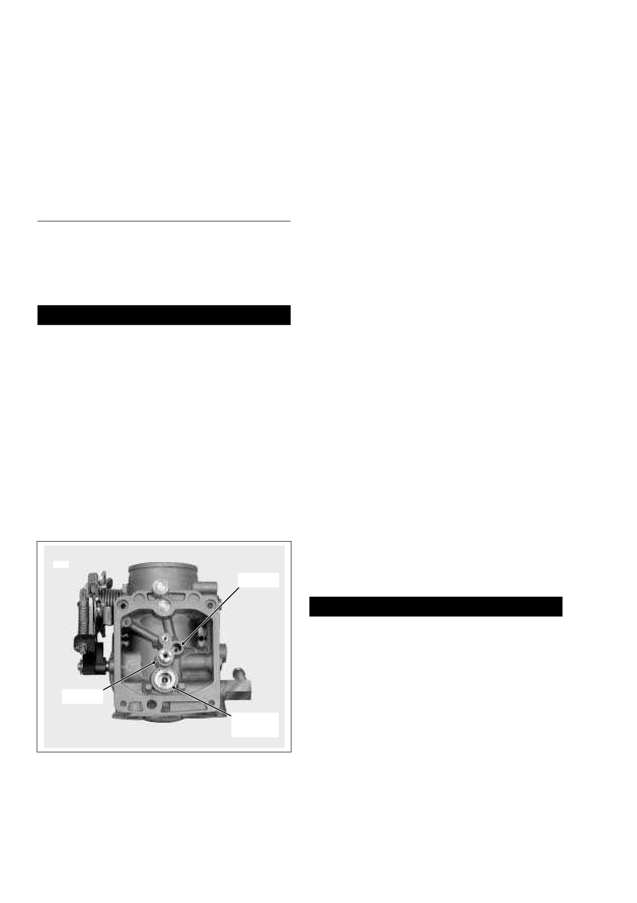
Slow Jet
pressure compressed air.
1WARNING
Compressed air can pierce the skin and flying debris
from compressed air could cause serious eye injury.
Wear safety glasses when working with compressed air.
Never use your hand to check for air leaks or to deter-
mine air flow rates. (00061a)
2.
Inspect parts as follows:
Main Jet
a. Hold vacuum piston up to strong light source. Exam-
Fuel Valve
ine diaphragm for pin holes, cuts, tears or pinching.
Bore
Replace if any damage is found.
b. Examine passage at bottom of vacuum piston bore.
Figure 4-10.
Carburetor Housing
Verify that passage is clean and open.
4-12
2006 Touring: Fuel
HOME
Float Chamber Components
8980
1.
Thorougly clean all loose parts with carburetor cleaner.
A
See Figure 4-8. Blow dry using low pressure com-
pressed air.
5
1WARNING
Compressed air can pierce the skin and flying debris
from compressed air could cause serious eye injury.
Wear safety glasses when working with compressed air.
Never use your hand to check for air leaks or to deter-
mine air flow rates. (00061a)
2.
Inspect parts as follows:
1
3
a. Inspect O-ring in groove of float bowl for cuts, tears
or signs of deterioration. Replace O-ring if distorted
or if sealing surface is damaged.
8978
b. Inspect float pin for damage or distortion. Replace
6
B
float pin if corroded, nicked or bent.
c. Clean float and inspect for cracks or other damage.
Submerge float in a glass of water. Replace float if
not water tight.
d. Depress pin on fuel valve to verify that it returns to
the full-out position. Thoroughly clean valve with
carburetor cleaner if pin is dirty or sticks. Inspect
rubber cone on valve for dirt, cracks, hardening or
wear. Inspect wireform clip for distortion. Replace
fuel valve assembly if any of these conditions are
4
found.
2
e. Inspect fuel valve seat in carburetor housing for dirt,
damage or corrosion. Replace carburetor if seat
damage or corrosion is present.
1.
Slow Speed Circuit Air Inlet
2.
Slow Jet Bore
f.
Verify cleanliness of main jet, needle jet holder and
3.
Main Circuit Air Inlet
needle jet. Verify that orifices in needle jet holder
4.
Main Jet Bore
are clean and open. Replace parts if damaged.
5.
Float Bowl Vent Air Inlet
6.
Vent Holes
g. Verify cleanliness of slow jet. Be sure that all orifices
are clean and open. Replace jet if damaged.
Figure 4-11. Clean Air/Fuel Passages
Accelerator Pump
c. Examine vacuum piston spring for stretching, kink-
h.
Inspect the accelerator pump diaphragm for holes,
ing, distortion or other damage. Inspect spring seat
cuts, tears or cracks. Replace diaphragm if
for cracks. Replace parts if necessary.
deformed or damaged.
d. Examine slides at sides of vacuum piston to verify
i.
Examine spring for stretching, kinking or distortion.
that surfaces are clean and smooth. Clean or buff
Replace if any damage is found.
out any rough surfaces.
j.
Inspect the accelerator pump rod for straightness.
e. Examine tip of jet needle for grooves or scratches.
Replace the rod if bent.
Needle should be completely straight, while surface
condition at taper should be smooth and even.
k. Inspect rubber boot and two O-rings for cuts, tears
Replace needle if necessary.
or signs of deterioration. Replace if necessary.
2006 Touring: Fuel
4-13
HOME
ASSEMBLY
A
Start Float Position
a0186x4x
Vacuum Piston Chamber
1.
Install vacuum piston into carburetor body. Slides on pis-
ton are offset, so piston will fit into slide track groove only
one way. If vacuum piston does not fit, rotate assembly
180°.
2.
Insert jet needle into vacuum piston bore, so that it
Float
enters center hole at bottom. In the installed position,
head of needle contacts boss at bottom of vacuum piston
bore, while length of shaft resides in main jet bore.
Intake Manifold Side Down
3.
With the legged side down, slide spring seat over top of
needle in vacuum piston bore. Slide spring over spring
B
Correct Float Position
seat.
4.
Verify that lip on edge of diaphragm is seated in groove
of carburetor flange.
NOTE
Diaphragm expands when in contact with fuel. If diaphragm is
difficult to seat in groove because of this condition, allow dia-
Float
phragm to dry before attempting to install.
5.
Fit free end of spring over boss on inboard side of carbu-
0.413- 0.453 in.
(10.49-11.51 mm)
retor top, and keeping spring straight, align holes in top
with those in flange.
6.
Holding top to flange, check for proper diaphragm seal
15˚ to 20˚
by pushing up on vacuum piston (from intake side) and
Pin Return Spring
releasing. If diaphragm is sealed correctly, very slight
Collapsed
resistance should be felt when pushing up, and piston
C Incorrect Float Position
should be slow to extend. If piston movement is
restricted, spring is cocked. Lift up on top and then lower
carefully keeping spring coils straight.
7.
Install three black top screws in holes furthest from throt-
tle wheel. Alternately tighten screws until snug.
8.
Slide gold top collar into remaining hole in carburetor top.
Float
With end of idle screw resting against idle cam stop,
align holes in throttle cable bracket with those in carbure-
tor body and top cover. To prevent bending bracket or
cam stop, first install gold Phillips screw
(with lock-
washer) at side of carburetor. At carburetor top, install
remaining Phillips screw.
Greater Than 20˚
9.
Carefully insert enrichener valve into carburetor bore.
Start threaded end of plastic fitting into bore, and then
rotate cable in a clockwise direction to install. Exercising
caution to avoid damaging the plastic construction,
Figure 4-12. Float Check and Adjustment
tighten fitting using a 14mm open end wrench. See Fig-
ure 4-5.
4.
Insert slow jet into slow jet bore. See Figure 4-10. Insert
Float Chamber
thin bladed flat tip screwdriver into bore, and using slot at
top of slow jet, tighten until snug.
1.
Place needle jet into main jet bore. See Figure 4-10. Be
sure end with chamfered edge and larger ID goes in first.
5.
Install wireform clip into groove on pin side of fuel valve,
if removed. Using wireform clip, carefully hang fuel valve
2.
Insert needle jet holder into main jet bore, and using a 5/
16 inch wrench, turn hex until snug.
onto tab of float, so that tip of rubber cone hangs flush
with top of float (the top being the side opposite the pivot
3.
Thread main jet into needle jet holder. Using slot at top of
arm).
main jet, tighten with flat tip screwdriver until snug.
4-14
2006 Touring: Fuel
HOME
6.
Place float into cavity of carburetor inserting fuel valve
f.
Install float and check float level again. Repeat pro-
into bore between pedestals. See Figure 4-10.
cedure as necessary until float level is within specifi-
cation.
CAUTION
9.
Install new O-ring into groove of float bowl, if removed.
Be sure to thoroughly clean groove before O-ring instal-
Tapping the float pin in from the rounded pedestal side
lation.
will result in damage that requires carburetor replace-
ment.
10.
Assemble accelerator pump as follows:
7.
Insert float pin through squared pedestal and pivot arm
a. With the flat side toward the casting, install two O-
of float into rounded pedestal. Since the rounded pedes-
rings into counterbores of accelerator pump lower
tal has an interference fit to ensure that the float pin is
housing.
securely held, always install pin from the loose side (in
the direction opposite the cast-in arrow). Using a small
b. Install diaphragm into accelerator pump upper
center punch and hammer, carefully tap float pin until
housing. Verify that lip on edge of diaphragm is fully
ends are flush with outboard sides of pedestals.
seated in groove.
8.
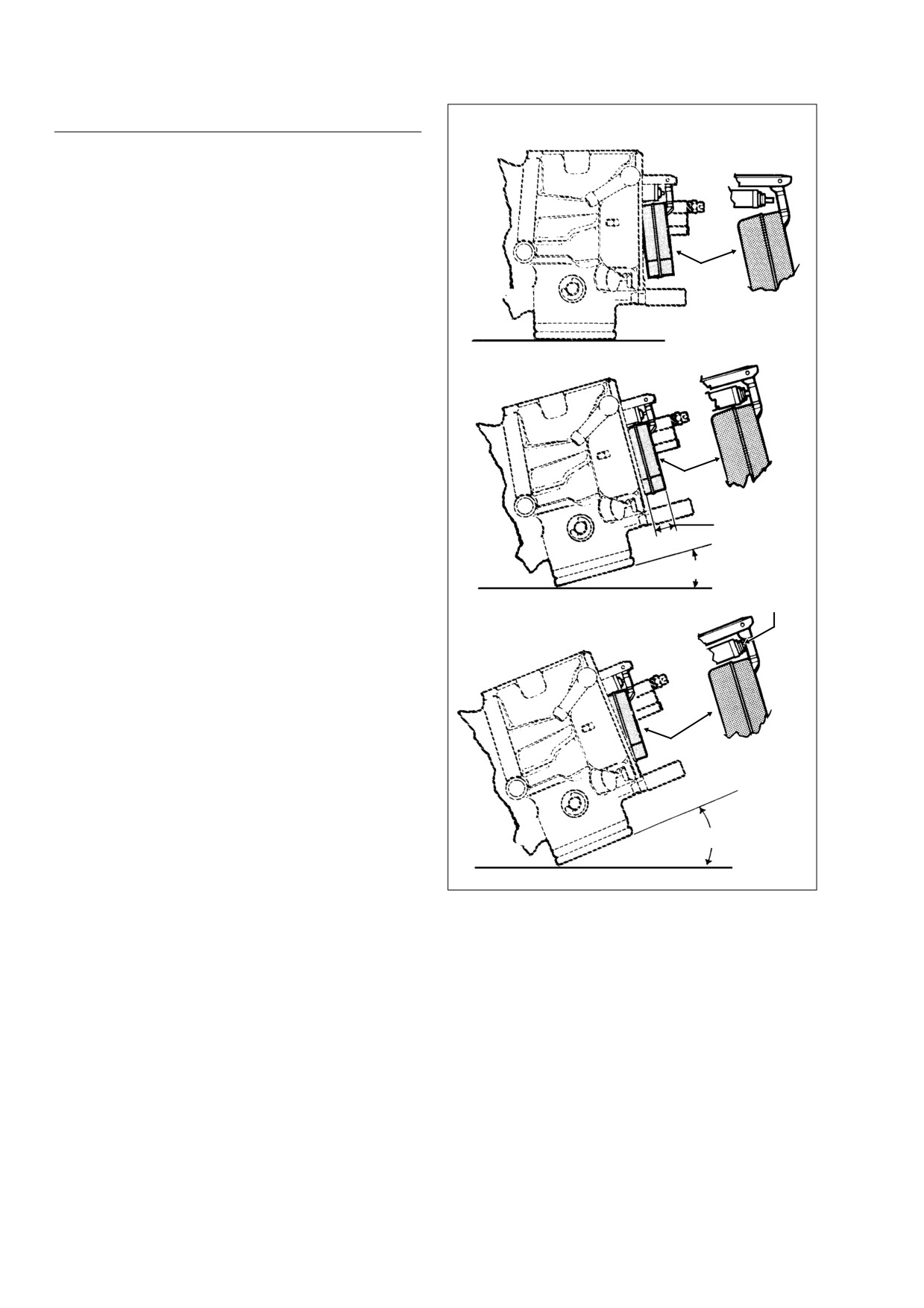
Perform float level check as follows:
c. Place spring onto spring seat at center of installed
diaphragm.
a. Place carburetor on a clean flat surface with the
intake manifold side down. See A of Figure 4-12.
d. Keeping spring straight, mate upper and lower
housings of accelerator pump. Install three Phillips
b. Tilt the carburetor 15° to 20° in a counter-clockwise
direction until float comes to rest. See B of Figure 4-
screws (with lockwashers).
12.
e. Install rubber boot onto post at top of accelerator
NOTE
pump upper housing.
The measurements will be incorrect if the carburetor is tilted
f.
Hook accelerator pump rod into hole on inboard
less than 15 ° or more than 20 °.
side of lever at side of carburetor body.
c. Using a dial vernier caliper or dial caliper depth
11.
Install float bowl at bottom of carburetor body engaging
gauge, measure the distance from the face of the
free end of accelerator pump rod in hole of rubber boot.
carburetor flange to the outboard edge of the float.
Be careful not to push on float while measuring.
12.
Install four Phillips screws to secure float bowl at bottom
d. If the measurement is between
0.413 inch and
of carburetor body. Tighten screws until snug.
0.453 inch (10.49 -11.51 mm), then the float level is
within specification. Proceed to step 9.
e. If the float level is not within specification, remove
the float, and referencing the table below, carefully
bend the tab slightly to adjust the float level. For
example, to increase the float measurement, bend
the tab toward the carburetor body. This will have
the affect of decreasing the amount of gas in the
float bowl after assembly.
Table 4-1. Float Level Tab
Float
Amount of Gas
Bend Tab
Measurement
in Float Bowl
Toward
To Increase
Decreased
Carburetor Body
Away From
To Decrease
Increased
Carburetor Body
2006 Touring: Fuel
4-15
HOME
AIR CLEANER
4.5
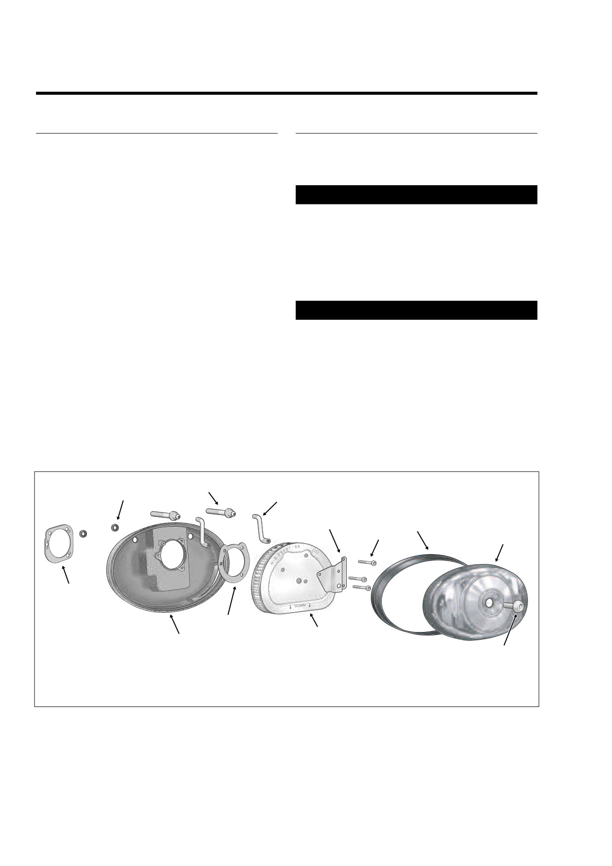
REMOVAL
CLEANING AND INSPECTION
1.
Thoroughly clean air cleaner cover, breather tubes and
1.
Remove large allen head socket screw in center of air
backplate with warm, soapy water.
cleaner cover. Remove air cleaner cover with rubber
2.
Clean the filter element as follows:
seal. See Figure 4-13.
2.
Remove three T27 TORX screws to release cover
1WARNING
bracket from filter element.
Do not use gasoline or solvents to clean filter element.
3.
Remove filter element pulling two breather tubes from
Flammable cleaning agents can cause an intake system
holes on inboard side.
fire, which could result in death or serious injury.
(00101a)
4.
Remove gasket from sleeve on inboard side of filter ele-
a. Wash the filter element in warm, soapy water. To
ment. Discard gasket.
remove soot and carbon, soak element for 30 min-
utes in warm water with mild detergent.
5.
Remove breather tubes from fittings on two cylinder
head breather bolts.
1WARNING
6.
Remove two cylinder head breather bolts from backplate
using a 7/16 inch deepwell socket.
Compressed air can pierce the skin and flying debris
from compressed air could cause serious eye injury.
7.
Remove backplate from cylinder heads. On carbureted
Wear safety glasses when working with compressed air.
California models, pull clean air inlet tube (to charcoal
Never use your hand to check for air leaks or to deter-
canister) from hole on inboard side of backplate.
mine air flow rates. (00061a)
8.
Remove two O-rings from grooves around breather bolt
b. Dry the filter element using low pressure com-
holes on inboard side of backplate. Discard O-rings.
pressed air (32 psi/221 kPa maximum). Rotate the
element while moving air nozzle up and down the
9.
Remove gasket from inboard side of backplate. Discard
element interior. Do not rap the element on a hard
gasket.
surface.
9
f1624x4x
11
8
5
3
4
2
12
7
6
10
1
1.
Cover Screw
4.
T27 Torx Screw (3)
7.
Gasket
10. Backplate
2.
Air Cleaner Cover
5.
Cover Bracket
8.
Breather Tube (2)
11. O-Ring (2)
3.
Rubber Seal
6.
Filter Element
9.
Breather Bolt (2)
12. Gasket
Figure 4-13. Air Cleaner Assembly
4-16
2006 Touring: Fuel
HOME
c. Hold the filter element up to a strong light source.
NOTE
The element can be considered sufficiently clean if
light is uniformly visible through the media.
Air cleaner mounting without installation of the breather
tubes allows crankcase vapors to be vented into the atmo-
NOTE
sphere in violation of legal emissions standards.
Replace the filter element if damaged or if filter media cannot
be adequately cleaned.
8.
Place filter element onto backplate with the flat side
down, so that hole on inboard side of element fits over
3.
Inspect the breather tubes and rubber seal for cuts,
molded boss in backplate.
tears, holes or signs of deterioration. Replace as neces-
sary. Direct compressed air through the breather tubes
9.
Align holes in cover bracket with those in filter element
to be sure that they are not plugged.
and start three T27 TORX screws. Stamp on cover
bracket points to downside. Alternately tighten screws to
40-60 in-lbs (4.5-6.8 Nm).
INSTALLATION
10.
Verify that rubber seal is properly seated around perime-
ter of air cleaner cover.
1.
Install new O-rings in grooves around breather bolt
11.
Fit air cleaner cover into backplate. Apply a small dab of
holes on inboard side of backplate.
Loctite Medium Strength Threadlocker
243 (blue) to
2.
Aligning flat edge of gasket with molded tab, install new
threads of large allen head socket screw. Install screw in
gasket on inboard side of backplate. On California mod-
center of air cleaner cover and tighten to 36-60 in-lbs
els, install gasket by aligning small holes with plastic
(4.1-6.8 Nm).
pins.
3.
On California models, push clean air inlet tube (to char-
coal canister) into hole on inboard side of backplate.
4.
Align holes in backplate with those in cylinder heads and
install cylinder head breather bolts. Using a 7/16 inch
deepwell socket, alternately tighten bolts to
120-
144 in-lbs (13.6-16.3 Nm).
5.
Slide new gasket over sleeve on inboard side of filter
element. Be sure holes in gasket are aligned with those
in filter.
6.
Insert breather tubes about 1/4 inch (6.4 mm) into holes
on inboard side of filter element.
7.
Install breather tubes onto fittings of two cylinder head
breather bolts.
2006 Touring: Fuel
4-17
HOME
VACUUM OPERATED FUEL VALVE (CARBURETED)
4.6
GENERAL
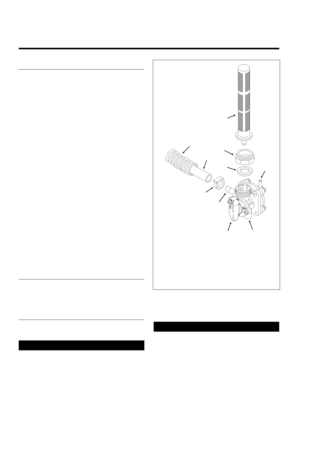
f1723x4x
A fuel valve is located under the fuel tank on the left side of
the motorcycle. The gasoline supply to the carburetor is
dependent upon the position of the valve handle as well as
the internal workings of the vacuum-operated valve.
To access the main fuel supply, turn the valve handle down
to the fully vertical position, so that the indicator points up to
ON. To access the reserve supply, turn the handle up to the
fully vertical position, so that the indicator points down to
8
RES(ERVE). Move the handle to the horizontal position to
shut the gasoline supply to the carburetor OFF. Always turn
the valve to the OFF position to refuel, or whenever the
engine is not running.
5
7
Gasoline will not flow through the fuel valve until the following
conditions are met:
4
1.
The valve handle must be turned to the ON or
9
6
RES(ERVE) position.
2.
A vacuum of approximately 0.5-1.0 inches of Mercury
(Hg) must be applied to the vacuum fitting at the back of
the fuel valve.
3
In service, the vacuum fitting is connected to the intake man-
ifold. The partial vacuum applied at the fitting creates a differ-
2
ence in pressure between the front side of the diaphragm
(which is vented to the atmosphere via the bottom fitting on
the fuel valve) and the rear. This pressure differential causes
the diaphragm to move against an internal spring, thereby
opening an orifice that enables the flow of gasoline to the
10
1
carburetor. When the vacuum at the vacuum fitting is
removed, the internal spring pressure closes the orifice,
which effectively halts the supply of fuel to the carburetor.
1.
Valve Handle
6.
Vacuum Fitting
2.
Fuel Outlet Fitting
7.
Jam Nut
3.
Hose Clamp
8.
Filter Strainer
4.
Carburetor Fuel
9.
Gasket
TROUBLESHOOTING
Inlet Hose
10.
Atmospheric
5.
Convoluted Tubing
Pressure Port
If the fuel valve is not functioning properly, refer to the trou-
bleshooting chart on the next page.
Figure 4-14. Vacuum Operated Fuel Valve
1.
Turn the handle of the fuel valve to OFF.
REMOVAL
1WARNING
DRAINING FUEL TANK
A small amount of gasoline may drain from the carbure-
tor fuel inlet hose when disconnected from the fuel valve
1WARNING
fitting. Thoroughly wipe up any spilled fuel immediately
and dispose of rags in a suitable manner. Gasoline is
When servicing the fuel system, do not smoke or allow
extremely flammable and highly explosive. Inadequate
open flame or sparks in the vicinity. Gasoline is
extremely flammable and highly explosive, which could
safety precautions could result in death or serious
injury.
result in death or serious injury. (00330a)
4-18
2006 Touring: Fuel

HOME
2.
Using a side cutters, cut clamp and remove hose from
CLEANING AND INSPECTION
fuel outlet fitting at the front of the fuel valve. See Figure
4-14. Drain free end of hose into a suitable container.
1.
Clean or replace the fuel filter strainer.
3.
Remove elbow of intake manifold vacuum tube from fit-
2.
Flush the tank. See Section 4.7 FUEL TANK (CARBU-
ting on inboard side of the fuel valve.
RETED), CLEANING AND INSPECTION.
4.
Attach a length of fuel hose to the fuel outlet fitting. The
hose must be long enough to reach a suitable gasoline
container.
INSTALLATION
5.
Turn the handle of the fuel valve to RES(ERVE).
6.
Using the correct hose adapter, connect the Mity-Vac®
1.
Install a new gasket on the valve head.
Hand Pump (HD-23738A) to the vacuum fitting.
2.
Install the fuel filter strainer fitting the internal tube into
the larger hole in the valve head.
CAUTION
3.
Clean threads and sealing surface of fuel tank adapter
To avoid damage to the diaphragm of the fuel valve, do
and inspect for damage. Replace if necessary. See
not apply a vacuum greater than 25 inches of Mercury
FUEL TANK ADAPTER on the next page.
(Hg) to the vacuum fitting.
4.
With the hex side down, turn the jam nut two full turns in
a counterclockwise direction to thread onto fuel tank
7.
Gently apply a vacuum of 1-10 inches of Mercury (Hg) to
adapter.
the vacuum fitting to get a good flow of gasoline through
the valve.
5.
Insert fuel filter strainer into fuel tank. Holding the hex
jam nut to prevent rotation, turn the fuel valve two full
8.
When the fuel tank is completely drained, remove the
turns in a clockwise direction to thread onto hex jam nut.
Mity-Vac® Hand Pump from the vacuum fitting.
9.
Holding fuel tank adapter, turn the hex jam nut in a
1WARNING
clockwise direction to remove the fuel valve assembly.
10.
Remove the fuel filter strainer from the valve head.
Do not thread fuel valve onto hex jam nut more than two
turns or nut may “bottom” on valve, a condition which
11.
Remove the hex jam nut from the fuel valve.
may result in a gasoline leak. Any gasoline leak is a
12.
Remove the gasket from the valve head. Discard the
potential fire hazard that could result in death or serious
gasket.
injury.
Table 4-2. Troubleshooting Vacuum Operated Fuel Valve
Problem
Cause
Solution
1.
Vacuum valve not opening.
1.1
Hose not connected to
1.1.1
Connect hose to vacuum fitting.
vacuum fitting.
1.2
Leaking diaphragm.
1.2.1
Replace fuel valve assembly.
1.3
Hose connected to
1.3.1
Connect hose to vacuum fitting.
atmospheric pressure port.
1.4
Vacuum hose assembly
1.4.1
Replace vacuum hose assembly.
pinched or cracked.
2.
Vacuum valve does not close.
2.1
Damaged sealing surface on
2.2.1
Replace fuel valve assembly.
valve side of diaphragm.
2.2
Plugged vacuum fitting.
2.2.2
Clean as necessary.
2.3
Broken or missing internal
2.3.1
Replace fuel valve assembly.
spring.
3.
Valve leaks gasoline at
3.1
Leaking diaphragm.
3.1.1
Replace fuel valve assembly.
atmospheric pressure port.
3.2
Loose diaphragm housing
3.2.1
Tighten screws.
screws.
2006 Touring: Fuel
4-19
HOME
6.
Holding the fuel valve to prevent rotation, turn the hex
jam nut in a counterclockwise direction until snug.
f2052x4x
Fuel Tank
Tighten the hex jam nut to 15-20 ft-lbs (20.3-27.1 Nm).
Side
CAUTION
Do not allow dirt or fluids to get into the vacuum tube
that connects the fuel valve to the intake manifold. Con-
taminants can block the vacuum signal which could
O-Ring
cause the fuel valve to malfunction.
7.
Connect elbow of intake manifold vacuum tube to fitting
on inboard side of the fuel valve.
Figure 4-15. Fuel Tank Adapter
8.
Slide new clamp onto free end of carburetor fuel inlet
hose. Install hose onto fuel outlet fitting at front of fuel
valve. Crimp clamp using HOSE CLAMP PLIERS (HD-
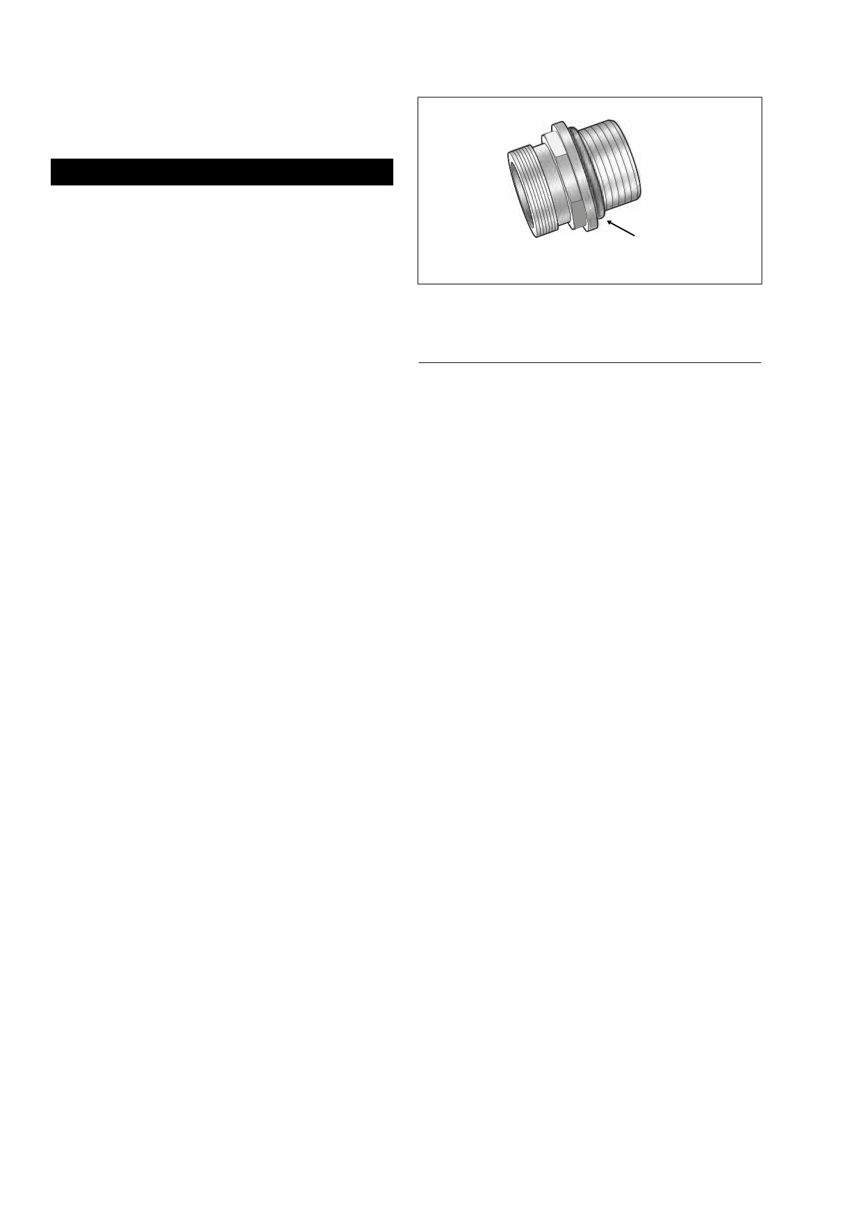
FUEL TANK ADAPTER
97087-65B).
9.
Turn the handle of the fuel valve to OFF and fill the fuel
If leakage or damage is observed at the fuel tank adapter,
tank. Carefully inspect for leaks at fitting.
replace O-ring and/or adapter as follows:
10.
Turn the valve handle to ON and start engine. No priming
1.
Remove fuel valve assembly. See REMOVAL in this sec-
or special procedures are required to start fuel flow.
tion.
Carefully inspect for leaks at fitting.
2.
Slide a 7/8 inch socket over hex on adapter, and looking
11.
Stop engine and return the valve to the OFF position.
down at top of fuel tank, rotate in a clockwise direction to
remove. See Figure 4-15.
3.
Remove O-ring from adapter. Discard O-ring.
4.
Apply a very thin film of clean H-D 20W50 engine oil to
new O-ring. Install O-ring into groove of adapter.
5.
Hand thread adapter into fuel tank bore. Looking down at
top of fuel tank, rotate adapter in a counterclockwise
direction until snug.
6.
Slide a 7/8 inch socket over hex and tighten to 22-26 ft-
lbs (30-35 Nm).
7.
Install fuel valve assembly. See INSTALLATION in this
section.
4-20
2006 Touring: Fuel
HOME
FUEL TANK (CARBURETED)
4.7
COMPLETE REMOVAL
f2385x8x
NOTE
For fuel injected models, see Section 9.4 FUEL TANK (FUEL
INJECTED) for removal and installation instructions.
FLHX, FLHT
1.
Remove seat. See Section 2.25 SEAT, REMOVAL.
1WARNING
To prevent accidental vehicle start-up, which could
cause death or serious injury, disconnect negative (-)
battery cable before proceeding. (00048a)
2.
Unthread bolt and remove battery negative cable (black)
from battery negative (-) terminal.
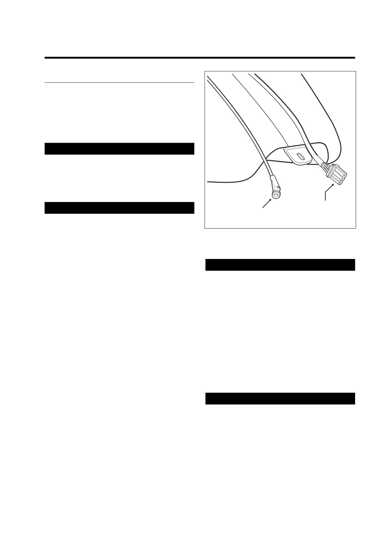
Fuel Tank Harness
1WARNING
Fuel Vapor Vent Tube
Connector [13]
(To Vapor Valve)
(Not Present on FLHR/C/S)
When servicing the fuel system, do not smoke or allow
open flame or sparks in the vicinity. Gasoline is
extremely flammable and highly explosive, which could
Figure 4-16. Fuel Level Sender Connector
result in death or serious injury. (00330a)
(FLHX, FLHT)
3.
Drain the fuel tank. See Section 4.6 VACUUM OPER-
ATED FUEL VALVE (CARBURETED), DRAINING FUEL
TANK, steps 1-8.
1WARNING
4.
Disconnect fuel tank harness connector [13], 4-place
A small amount of gasoline may drain from the cross-
Multilock, in front of battery. See Figure 4-16.
over hose when disconnected from the fuel tank. Thor-
5.
Remove two fuel tank front mounting bolts (with flat
oughly wipe up any spilled fuel immediately and dis-
washers) from left and right side of frame. Remove bolt
pose of rags in a suitable manner. Gasoline is extremely
(with flat washer) to free rear of fuel tank from frame
flammable and highly explosive. Inadequate safety pre-
backbone. On FLHX models, removal of rear bolt also
cautions could result in death or serious injury.
releases console bracket.
10. Using a side cutters, cut clamp from one end of cross-
6.
Open fuel door on console. Remove two Allen head
over hose beneath fuel tank. Drain free end of hose into
screws inboard of rubber bumpers. These screws secure
a suitable container.
console to clip nuts on the canopy bracket. If present,
also remove Allen head screw to detach flange at rear of
11. Remove fuel tank from motorcycle.
console from clip nut on fuel tank weldment (absent on
FLHX models).
7.
Lay a clean shop cloth on forward part of rear fender.
FLHR/S
Remove filler cap from neck of fuel tank. Remove con-
sole and lay upside down on shop cloth. Reinstall filler
1.
Remove seat. See Section 2.25 SEAT, REMOVAL.
cap.
8.
Gently pry fuel vapor vent tube from fitting on filler neck
1WARNING
of fuel tank. Exercise caution to avoid pulling fitting from
To prevent accidental vehicle start-up, which could
filler neck.
cause death or serious injury, disconnect negative (-)
9.
Remove two fuel tank front mounting bolts (with flat
battery cable before proceeding. (00048a)
washers) from left and right side of frame. Remove bolt
(with flat washer) to free rear of fuel tank from frame
2.
Unthread bolt and remove battery negative cable (black)
backbone.
from battery negative (-) terminal.
2006 Touring: Fuel
4-21
HOME
CLEANING AND INSPECTION
1WARNING
When servicing the fuel system, do not smoke or allow
1.
Inspect the fuel tank for leaks and other damage.
open flame or sparks in the vicinity. Gasoline is
Replace damaged tanks that cannot be successfully
extremely flammable and highly explosive, which could
repaired.
result in death or serious injury. (00330a)
2.
If sludge, rust or varnish deposits are evident, clean fuel
3.
Drain the fuel tank. See Section 4.6 VACUUM OPER-
tank as follows:
ATED FUEL VALVE (CARBURETED), DRAINING FUEL
TANK, steps 1-8.
1
WARNING
4.
Remove two fuel tank front mounting bolts (with flat
Even with the fuel tank completely drained, a small
washers) from left and right side of frame. Remove bolt
amount of gasoline may leak from the bore when the fuel
(with flat washer) to free rear of fuel tank from frame
valve is loosened or removed. Thoroughly wipe up any
backbone. On FLHRS models, removal of rear bolt also
spilled fuel immediately and dispose of rags in a suitable
releases instrument console bracket.
manner. Gasoline is extremely flammable and highly
explosive. Inadequate safety precautions could result in
5.
Remove acorn nut from instrument console. If present,
death or serious injury.
also remove Phillips screw and large flat washer (absent
on FLHRS models).
a. Remove the fuel valve assembly and plug fuel tank
6.
Raise instrument console and bend back flexible clamp
opening. See Section
4.6 VACUUM OPERATED
on canopy to release main harness conduit. Remove fuel
FUEL VALVE (CARBURETED), REMOVAL.
level sender connector [141], 4-place Packard, at top of
b. Remove canopy as follows:
canopy.
FLHX, FLHT, FLTR: See Section 8.30 FUEL LEVEL
SENDER (CARBURETED), FLHX, FLHT CAN-
CAUTION
OPY, REMOVAL, steps 10-12.
When removing instrument console, exercise caution to
FLHR: See Section 8.30 FUEL LEVEL SENDER
avoid damaging speedometer unit. Wrap console in a
(CARBURETED), FLHR/S CANOPY, REMOVAL,
clean, dry shop towel to prevent damage.
steps 10-12.
7.
Secure instrument console to top of rear fender using
bungee cords.
1WARNING
8.
Remove console mounting bolt from slot at top of can-
An open flame or spark may cause a fuel tank explosion
opy.
if all traces of fuel are not purged from the tank. Use
extreme caution when servicing fuel tanks. Inadequate
9.
Gently pry fuel vapor vent tube from fitting.
safety precautions could result in death or serious injury.
10. At bottom left side of fuel tank, gently pull on convoluted
c. Fill the tank with commercial cleaning solvent or a
tubing to draw fuel gauge connector [117], 4-place Mul-
soap and water solution. Shake the tank to agitate
tilock, out of tunnel. Depress button on socket terminal
the cleaning agent.
side and pull apart pin and socket halves.
1WARNING
1WARNING
Use only lead pellets to loosen deposits. Metal balls,
A small amount of gasoline may drain from the crossover
such as ball bearings, can cause a spark and explosion,
hose when disconnected from the fuel tank. Thoroughly
which could result in death or serious injury. (00261a)
wipe up any spilled fuel immediately and dis-pose of rags
in a suitable manner. Gasoline is extremely flammable
d. If necessary, non-ferrous metallic balls or pellets
and highly explosive. Inadequate safety precautions
may be added to the tank to help loosen deposits.
could result in death or serious injury.
e. Thoroughly flush the fuel tank after cleaning. Allow
11. Using a side cutters, cut clamp from one end of cross-
tank to air dry.
over hose beneath fuel tank. Drain free end of hose into
a suitable container.
f.
Install fuel valve assembly. See Section 4.6 VAC-
UUM OPERATED FUEL VALVE (CARBURETED),
12. Remove fuel tank from motorcycle.
INSTALLATION.
4-22
2006 Touring: Fuel