Harley Davidson FLHRC 2006. Maintenance & Repair Manual - page 15
HOME
7.
Push on bottom of valve until it contacts the valve seat.
Placing finger at bottom of valve to keep valve seated,
8702
A
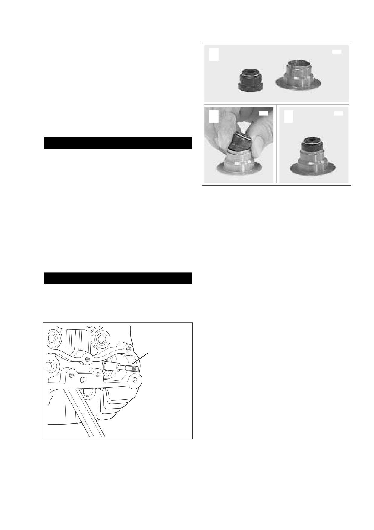
slide plastic capsule over valve stem tip and keeper
groove. See Figure 3-81.
8.
Apply a very thin film of clean H-D 20W50 engine oil to
capsule.
9.
Obtain new valve stem seal and spring seat. Assemble
parts as shown in Figure 3-82.
10. Slide valve stem seal/spring seat over capsule and down
valve stem until contact is made with top of valve guide
8703
8704
B
C
and machined area of cylinder head casting. Remove
capsule from valve stem tip.
CAUTION
Removing the valve after seal installation will cause the
valve stem seal to catch the edge of the valve stem
keeper groove. The resulting damage will lead to leakage
around the valve stem, excessive oil consumption and
valve sticking.
Figure 3-82. Valve Stem Seal/Spring Seat Assembly
11. Apply a liberal amount of assembly lube to valve stem tip
and keeper groove.
12. With the smaller diameter coils topside, install the valve
b. Rotate forcing screw to compress valve spring.
spring over the valve guide. Place the spring retainer on
top of the valve spring.
c. With the tapered side down, fit the keepers into the
13. Obtain the VALVE SPRING COMPRESSOR
(HD-
valve stem groove. For best results, apply a dab of
34736B) and proceed as follows:
grease to the inboard side of the keepers before
installation and use a magnetic rod for easy place-
a. Place tool over cylinder head so that the blunt end is
ment.
centered on the valve head and adapter at end of
forcing screw is seated on the spring retainer.
d. Arranging tapered keepers so that the gaps are
evenly spaced, turn forcing screw to release valve
spring compression.
CAUTION
Over-compressing the valve spring can damage the
14. Tap the end of the valve stem once or twice with a soft
valve stem seal resulting in leakage around the valve
mallet to ensure that tapered keepers are tightly seated
stem, excessive oil consumption and valve sticking.
in the valve stem groove.
15. Repeat steps 1-14 to install the other valve components.
16. Release the cylinder head holding fixture from the vise
f2411x3x
and then remove the tool from the spark plug hole.
17. Cover the cylinder head to protect it from dust and dirt
Plastic
Capsule
until time of installation.
Installation
See Section 3.9 TOP END OVERHAUL, ASSEMBLY, steps
15-24 and 29-39.
Figure 3-81. Lubricate Plastic Capsule
2006 Touring: Engine
3-67
HOME
CYLINDER
Removal
1.
See Section 3.9 TOP END OVERHAUL, DISASSEM-
BLY, steps 1-11 and 15-24.
Cleaning and Inspection
CLEANING
1.
Scrape old gasket material from the machined surface at
the top of the cylinder. Old gasket material left on the
Figure 3-83. Cylinder Torque Plates
mating surface will cause leaks.
(Part No. HD-42324A)
2.
Clean cylinder in a non-volatile cleaning solution or sol-
vent. Thoroughly dry with low pressure compressed air.
Verify that oil passageways are clean and open.
Lower Plate
A
Bolts
3.
Inspect the cylinder bore for defects or damage in the
ring travel area. Replace cylinders that are severely
scored, scuffed, scratched, burnt or gouged.
4.
Using Magnaflux Dye Penetrant, inspect the cylinder for
cracks. If no cracks are found, thoroughly wash cylinder
to remove traces of dye.
5.
Use a file to carefully remove any nicks or burrs from the
machined surfaces of the cylinder.
6.
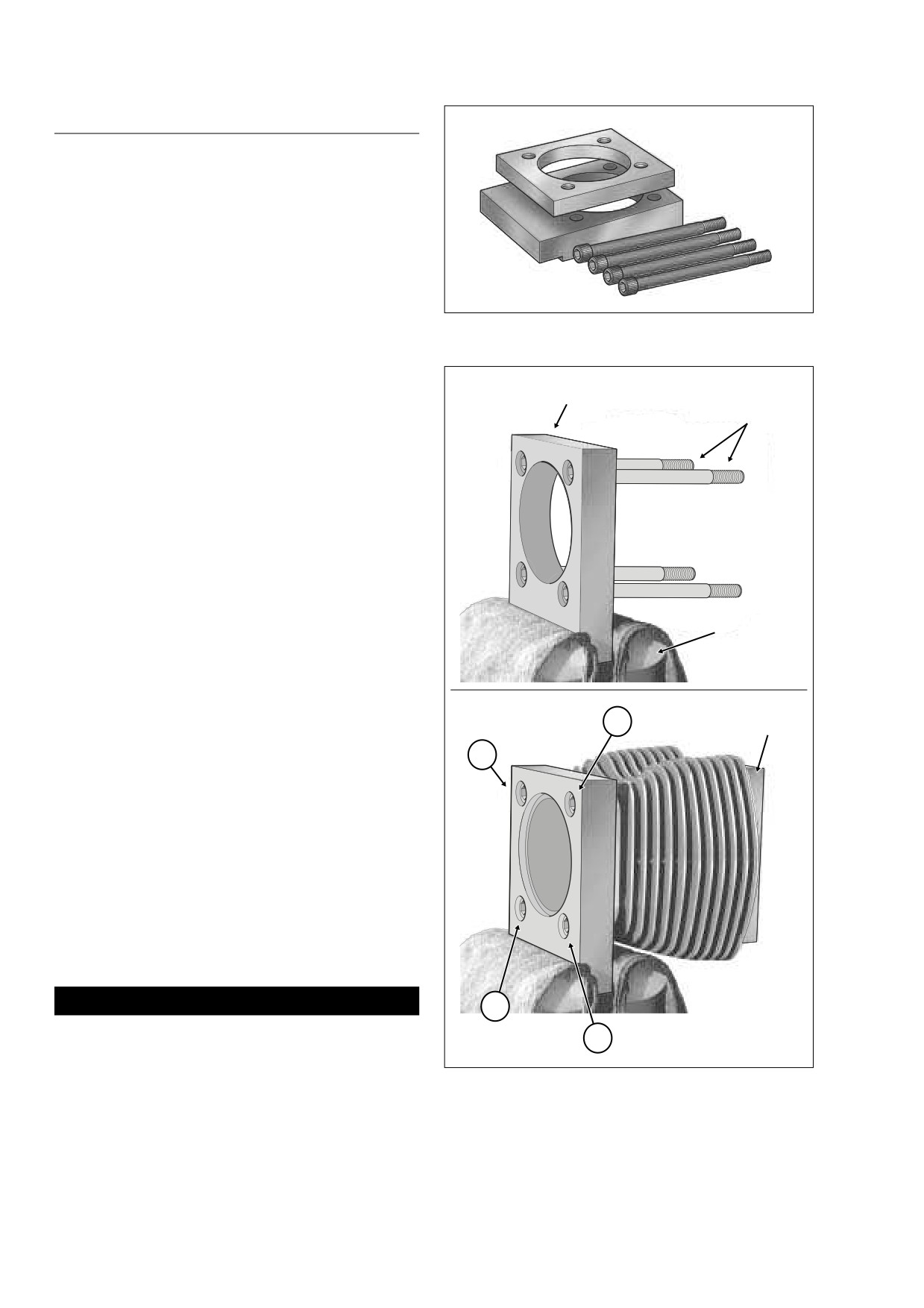
Using a feeler gauge and the CYLINDER TORQUE
PLATES (HD-42324A), check the machined surfaces for
flatness. Proceed as follows:
a. Lay gasket side of the upper plate (without vise grip)
Vise
flat against the head gasket surface.
b. As a preliminary check, see if the plate rocks from
f2075x3x
side to side. A cylinder on which the plate rocks is
immediately suspect.
c. Insert a feeler gauge between the plate and cylinder
3
B
Upper Plate
at various locations.
4
d. The head gasket surface must be flat within 0.006
inch (0.15 mm).
e. Now turn the cylinder upside down and lay the seal
side of the lower plate (with vise grip) flat against
the O-ring seal surface. Repeat steps 6(b) and 6(c).
f.
The O-ring seal surface must be flat within 0.004
inch (0.102 mm).
g. Replace the cylinder (and piston) if either surface is
not within specification.
INSPECTION
CAUTION
2
Failure to use the cylinder torque plates can produce
1
measurements that vary by as much as 0.001 inch (0.025
f2074x3x
mm), possibly resulting in the use of parts that are not
suitable for service.
Figure 3-84. Install Cylinder to Torque Plates
3-68
2006 Touring: Engine
HOME
1.
To simulate an assembled cylinder for accurately mea-
suring cylinder taper and out-of-round conditions, as well
f1686x3x
as for boring, honing or deglazing, obtain the CYLIN-
DER TORQUE PLATES (HD-42324A). Install the torque
plates as follows:
a.
Remove O-ring seal from cylinder sleeve, if
installed.
b.
Place used head gasket over two ring dowels at top
of cylinder.
c.
Install brass jaws or shop towels around teeth of
vise to prevent damage to tool. Clamp stepped side
of lower plate in vise with the simulated split line
(machined strip) facing away.
d.
Lightly oil threads and shoulders of four bolts with
clean H-D 20W50 engine oil. Slide bolts all the way
through holes of lower plate. See A of Figure 3-84.
e.
Slide cylinder down bolts with the indent in the cool-
ing fins facing upward.
f.
With the head gasket in place, align holes in upper
plate with ends of bolts. Blind holes in upper plate
accommodate ring dowels in cylinder. Alternately
tighten four bolts into upper plate until finger tight.
Figure 3-85. Measure for Out-of-Round and Taper
g.
Tighten the bolts to 120-144 in-lbs (13.6-16.3 Nm)
in the sequence shown in B of Figure 3-84.
c. Repeat the measurements again at the bottom of
h.
Following the same sequence, tighten each bolt to
the bore at a point below the piston ring travel zone.
15-17 ft-lbs (20.3-23.1 Nm).
d. Rebore the cylinder if the parallel and perpen-
i.
Using a grease pencil, mark a straight line on one of
dicular measurements at either the top, middle or
the bolts continuing the line over onto the lower
bottom of the bore vary by more than 0.002 inch
plate. Repeat step for remaining three bolts. Using
(0.051 mm), which indicates an out-of-round condi-
the marks as a guide, turn each bolt 1/4 turn or 90
tion.
degrees. Be sure to tighten the bolts in the
sequence shown in B of Figure 3-84.
Rebore the cylinder if the top, middle and bottom
bore diameters either parallel or perpendicular to
NOTE
the crankshaft vary by more than 0.002 inch (0.051
mm), which indicates excessive taper.
For
best results, obtain Snap-on® Torque Angle Gauge
TA360.
CAUTION
j.
For purposes of inspection, remove the assembly
from the vise and place on bench top.
Maximum cylinder wear occurs at the very top of top ring
travel. Minimum wear occurs below ring travel. Failure to
2.
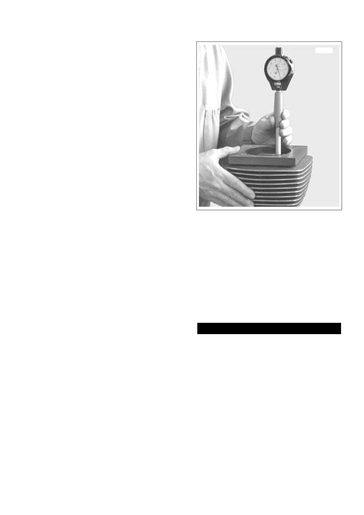
See Figure 3-85. Using an inside micrometer or dial bore
measure the cylinder at these points may result in a
gauge, check cylinder bore for out-of round and taper.
faulty decision regarding the suitability of the cylinder
Proceed as follows:
for continued use.
a. At the top of the piston ring travel zone (starting
3.
If cylinders are not scuffed or scored, and are not worn
about 0.50 inch or 12.70 mm from the top of the cyl-
beyond the service limits described under step 2(d), see
inder), measure the cylinder diameter at two loca-
DEGLAZING CYLINDER on the next page.
tions- parallel and perpendicular to the crankshaft.
On the other hand, if cylinders are worn beyond the ser-
Write the readings down.
vice limits, then they must be rebored and/or honed to
b. Repeat the two measurements at the center of the
accept the next standard oversize piston. See BORING
piston ring travel zone.
AND HONING CYLINDER on the next page.
2006 Touring: Engine
3-69
HOME
DEGLAZING CYLINDER
2.
Hone the cylinder to its finished size using a 280 grit
rigid hone.
NOTE
Deglazing removes wear patterns, minor scuff marks and
3.
Stop frequently to examine the cylinder bore and/or take
scratches without enlarging the bore diameter.
measurements. Remember, a precise 60˚ cross hatch
pattern in the piston travel area is important.
1.
Lightly swab the cylinder bore with a cloth dipped in
clean engine oil.
4.
Thoroughly wash the cylinder bore with liquid dishwash-
ing soap and warm water to remove all abrasive parti-
2.
Obtain a 240 grit flexible ball-type deglazing tool with a
cles and residual grit. Continue cleaning until a clean
bristle tip or finishing stone arrangement able to produce
cloth shows no evidence or dirt or debris.
a 60˚ cross hatch pattern.
3.
Install the deglazing tool in a slow-speed drill. The speed
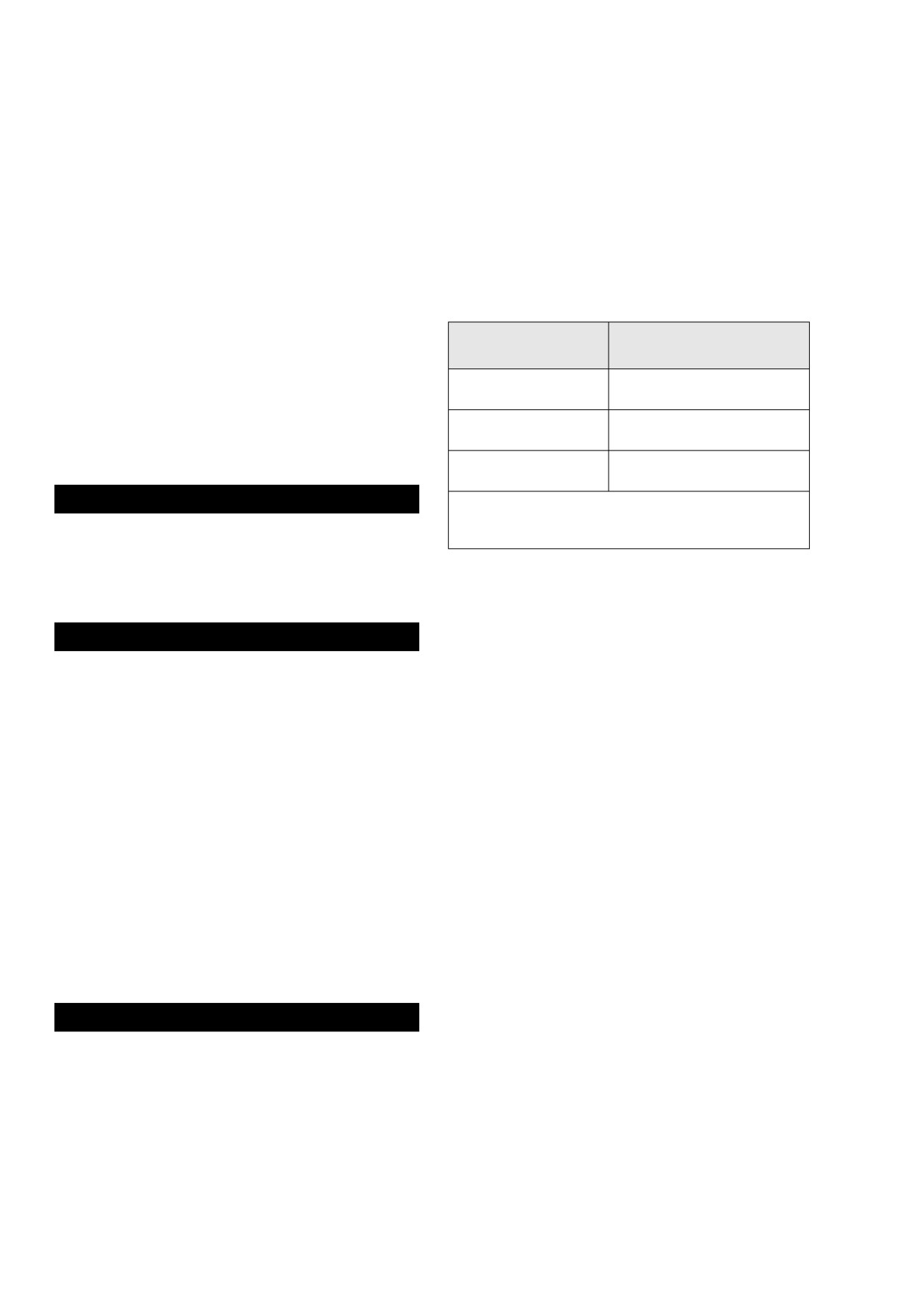
Table 3-7. Oversize Pistons
at which the tool rotates determines the speed at which
it must be stroked up and down the bore to produce the
Cylinder Bore
Piston
desired cross hatch pattern.
Finished Size
4.
Starting at the bottom of the cylinder, move the deglaz-
3.7500 - 3.7505 in.
ing tool up and down the entire length of the cylinder
Standard
(95.250 - 95.263 mm)
bore for 10 to 12 complete strokes.
0.005 In. (0.13 mm)
3.7550 - 3.7555 in.
5.
Stop to examine the cylinder bore and/or take measure-
Oversize
(95.377 - 95.390 mm)
ments. A precise 60˚ cross hatch pattern in the piston
travel area is the most important.
0.010 In. (0.25 mm)
3.7600 - 3.7605 in.
Oversize
(95.504 - 95.517 mm)
CAUTION
Example: A 0.005 in. (0.13 mm) oversize piston will have
the proper running clearance with a cylinder bore size of
The angular cross hatch pattern ensures an even flow of
3.7550 - 3.7555 in. (95.377 - 95.390 mm).
oil onto the cylinder walls and promotes longer cylinder,
piston and ring life. An Improper crosshatch pattern will
result in insufficient oil retention and possible piston
5.
Hot rinse the cylinder and dry with moisture free com-
seizure and/or high oil consumption.
pressed air. Immediately apply a thin film of clean engine
oil to prevent rusting.
CAUTION
6.
With the cylinder at room temperature, check the piston
Failure to remove all abrasive particles may result in pre-
clearance in the cylinder in which the piston will run. See
mature cylinder, piston and ring wear and possible
PISTON, INSPECTION, step 5.
engine failure.
6.
Thoroughly wash the cylinder bore with liquid dishwash-
ing soap and warm water to remove all abrasive parti-
Installation
cles and residual grit. Continue cleaning until a clean
cloth shows no evidence or dirt or debris.
1.
See Section 3.9 TOP END OVERHAUL, ASSEMBLY,
7.
Hot rinse the cylinder and dry with moisture free com-
steps 8-24 and 29-39.
pressed air. Immediately apply a thin film of clean engine
oil to prevent rusting.
8.
With the cylinder at room temperature, check the piston
clearance in the cylinder in which the piston will run. See
PISTON, INSPECTION, step 5.
BORING AND HONING CYLINDER
1.
Bore the cylinder to 0.003 inch (0.08 mm) under the
desired finished size. See Table 3-7.
CAUTION
An improper crosshatch pattern or too fine a hone will
result in insufficient oil retention and possible piston
seizure and/or high oil consumption.
3-70
2006 Touring: Engine
HOME
6.
Using Magnaflux Dye Penetrant, inspect the piston for
PISTON
surface cracks. Pay special attention to the area around
the pin bores, ring lands and oil drain holes beneath the
piston crown. If no cracks are found, thoroughly wash
Removal
piston to remove traces of dye.
1.
See Section 3.9 TOP END OVERHAUL, DISASSEM-
BLY, steps 1-11 and 15-29.
Inspection
1.
Lightly oil a good piston pin and insert it into the piston
pin bore to feel for the proper interference fit. The pin
Disassembly
should slide in and out without binding, but also without
pivoting or rocking. Replace piston and/or pin if clear-
Piston Rings, Removal
ance exceeds 0.0008 in. (0.020 mm).
2.
Carefully inspect the pistons for damage or excessive
1WARNING
wear. Discard pistons with cracked, broken or bent ring
lands. Check the piston skirt for cracks, gouges, deep
Always wear proper eye protection when removing the
scratches or heavy scoring. Check the piston heads for
compression rings. Slippage may propel the ring with
evidence of burning, etching or melting. Look for marks
enough force to cause eye injury.
or imprints caused by contact with valves. Pistons with
superficial wear marks, minor scratching or mild scoring
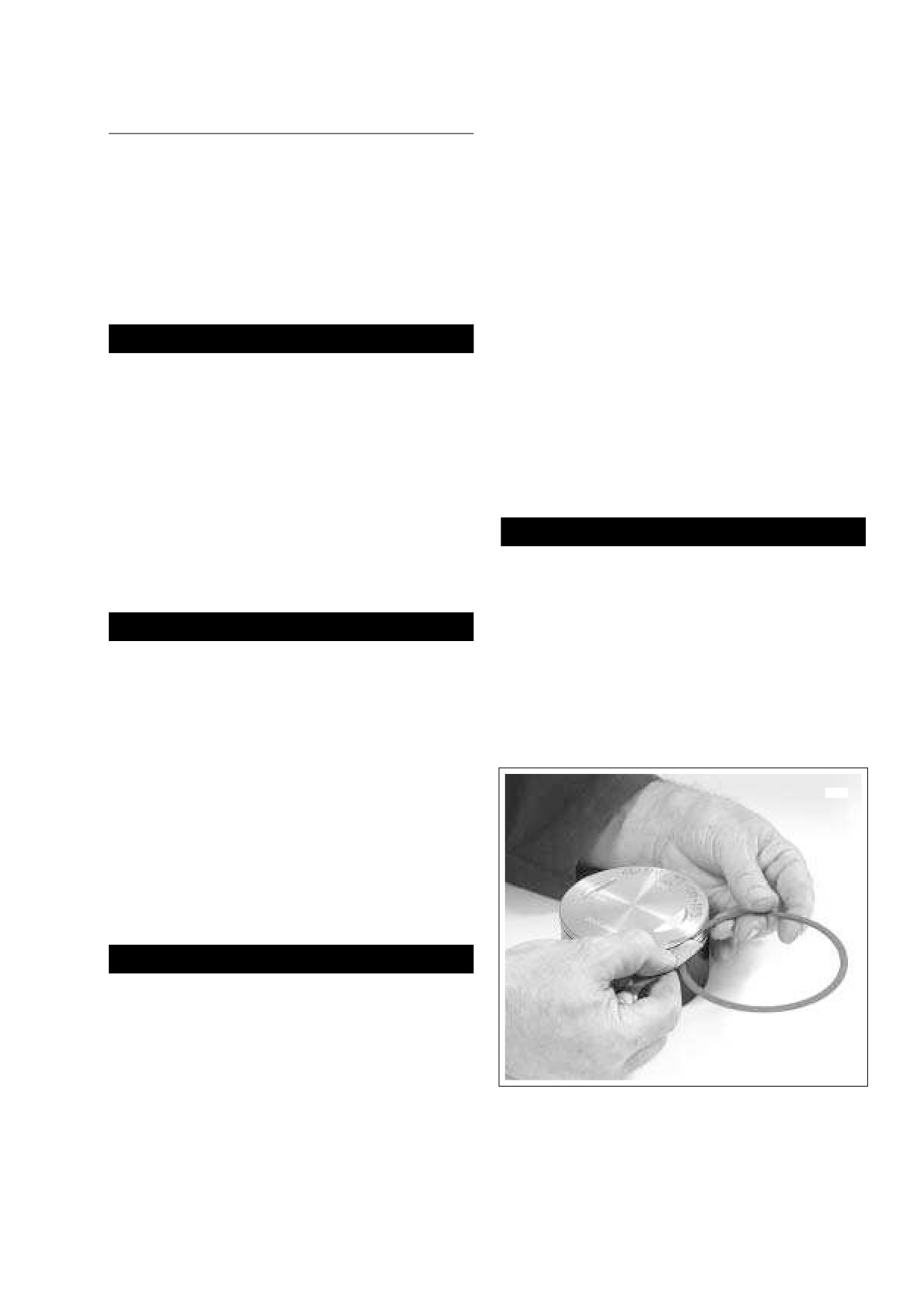
1.
Carefully remove first and second compression rings
may continue to be used.
using the proper piston ring expander (Snap-On PRS8).
3.
Run your index finger around the edge of the piston
2.
Using your fingers, remove the top and bottom oil rails
crown to feel for dings, nicks or burrs. Lightly file the
from the third ring groove. Remove the expander spring.
edge of the crown to remove any defects.
3.
Discard the piston rings.
CAUTION
Cleaning and Inspection
Worn ring grooves result in high oil consumption and
blow-by of exhaust gases. Blow-by of exhaust gases
Cleaning
contaminates the engine oil supply with acids and
leaves sludge in the crankcase. It also reduces engine
CAUTION
efficiency by weakening the combustion seal necessary
for efficient transfer of energy to the piston.
Do not sand blast or glass bead blast pistons. Bead
blasting rounds off ring lands and will result in oil con-
4.
Measure the piston ring side clearance as follows:
tamination leading to accelerated wear.
a. Insert the edge of a new ring into the piston ring
groove. Insert a feeler gauge between the upper
1.
To remove all carbon and combustion deposits, soak the
surface of the ring and the ring land. See Figure 3-
pistons in a special detergent that will not corrode alumi-
86.
num. Maintain the temperature of the cleaning solution
well below 212o F. (100o C.).
2.
Thoroughly rinse the pistons and dry with moisture free
6906
compressed air.
3.
Clean the oil drain holes leading from the oil control ring
groove to the underside of the piston crown. Run a small
bristle brush through the passageways to ensure their
cleanliness, but be careful not to damage or enlarge the
holes. Do not use a wire brush.
4.
Verify that all other oil holes are clean and open.
CAUTION
Exercise care to avoid scratching the sides of the piston
ring grooves.
5.
Thoroughly clean the three piston ring grooves of all car-
bon deposits. A broken compression ring properly
ground to a sharp chisel-like edge may be used for this
purpose.
Figure 3-86. Measure Piston Ring Side Clearance
2006 Touring: Engine
3-71
HOME
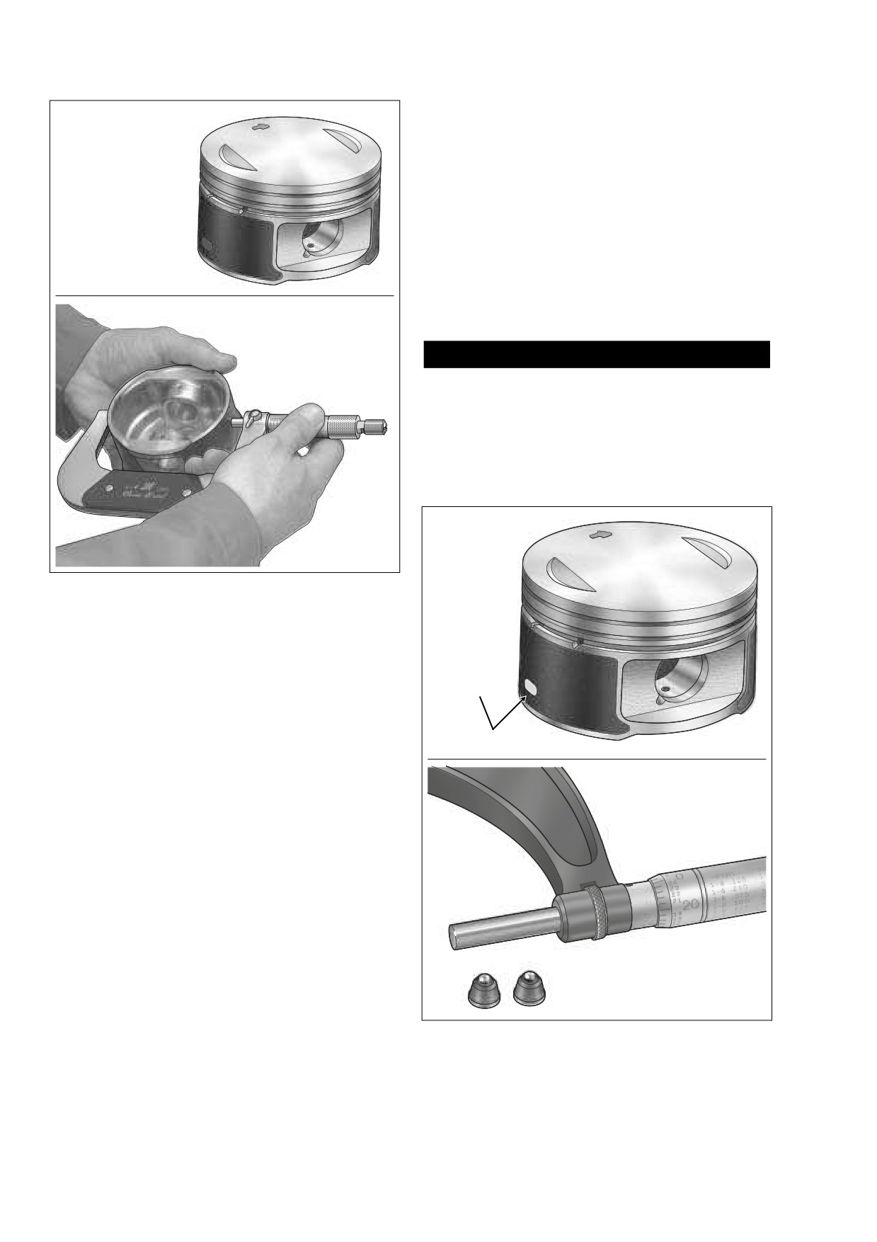
NOTE
On late style pistons, the measurement is taken on the bare
aluminum to avoid measuring errors. An oval-shaped open-
EARLY STYLE
ing is present on each side of the piston for proper placement
of the micrometer. See upper frame of Figure 3-88. Since the
FULLY COATED
oval openings are too small for a standard flat anvil microme-
No Bare
ter, which would result in measuring errors, use a 3-4 inch
Aluminum
blade or ball anvil style micrometer, or a 4-5 inch micrometer
with spherical ball anvil adapters. See lower frame of Figure
3-88.
f2114x3x
c. Using a grease pencil, mark the top, middle and
bottom of the piston ring travel zone in the cylinder
bore. Measure at markings in cylinder parallel and
perpendicular to crankshaft.
CAUTION
Do not check piston running clearance immediately after
honing or deglazing cylinder. Since heat will cause mea-
surements to vary by as much as 0.0002 inch (0.005 mm),
both piston and cylinder must be at room temperatures.
d. Replace piston and/or cylinder if running clearance
exceeds 0.003 in. (0.076 mm).
LATE STYLE
f1685x3x
Figure 3-87. Measure Early Style Piston for
Running Clearance
b. Since the grooves wear unevenly, repeat this check
at several locations around the piston groove cir-
cumference.
Bare
Aluminum
c. Discard the piston if the side clearance of either
compression ring exceeds 0.0045 in. (0.11 mm).
Discard the piston if the oil control ring side clear-
ance exceeds 0.010 in. (0.25 mm).
f2113x3x
5.
Measure the running clearance on fully coated early
style pistons as follows:
NOTE
Check the piston clearance in the cylinder in which the piston
4-5 Inch
will run. The torque plates must be installed on the cylinder
Micrometer
and it must be deglazed and suitable for continued service.
a. Holding outside micrometer, measure piston skirt
diameter across the thrust faces (perpendicular to
pin bore). Start below the bottom ring land and
move micrometer towards bottom of skirt. Microme-
ter will be loose, then tight (about 1/2 inch from bot-
tom), and then loose again. See lower frame of
Figure 3-87.
Spherical Ball
b. Measure the piston skirt at the tightest spot and
Anvil Adapters
f2109x3x
then transfer that measurement to the dial bore
gauge.
Figure 3-88. Measure Late Style Piston for
Running Clearance
3-72
2006 Touring: Engine
HOME
NOTE
Ring end gap dimensions also apply to oversize rings.
Replace ring if end gap exceeds specification. If end gap is
under specification, filing is permissible.
3.
Use compressed air to remove any dirt or dust that may
have settled in the oil drain holes and piston ring
grooves.
4.
Install piston rings as follows:
a.
Apply clean H-D 20W50 engine oil to three piston
ring grooves.
b.
Install expander spring into third ring groove. Spiral
bottom oil rail into space below expander spring
positioning the gap 90 degrees from the gap in the
6905
expander spring. Spiral top oil rail into space above
expander spring positioning gap 180 degrees from
the gap in the bottom oil rail.
Figure 3-89. Measure Ring End Gap
Assembly
Piston Rings, Installation
4
3
NOTE
Always use new piston rings. Piston rings take a definite set
and must not be reused if the engine has been operated.
FRONT
Always deglaze (or hone) the cylinder before installing new
rings. Ring sets are available to fit oversize pistons.
1.
Before placing each ring on the piston, perform the fol-
lowing check.
CAUTION
2
1
5
Insufficient ring end gap may cause the ends to abut at
engine operating temperatures, resulting in ring break-
2
1
5
age, cylinder scuffing and/or piston seizure.
CAUTION
REAR
Excessive ring end gap results in high oil consumption
and blow-by of exhaust gases. While blow-by contami-
nates the oil supply and leaves sludge in the crankcase,
it also reduces engine efficiency by weakening the com-
bustion seal necessary for efficient transfer of energy to
the piston.
4
3
2.
Insert the new ring into the cylinder, square it in the bore
using the top of the piston and measure the ring end gap
with a feeler gauge. See Figure 3-89. Do not use the ring
1.
Expander spring
if the end gap does not fall within the following specifica-
2.
Bottom oil rail
tions.
3.
Top oil rail
f2066x3x
Table 3-8. Ring End Gap
4.
Second compression ring
5.
Top compression ring
Ring Type
Ring End Gap
Top compression ring
0.010 in. (0.25 mm) - 0.020 in. (0.51 mm)
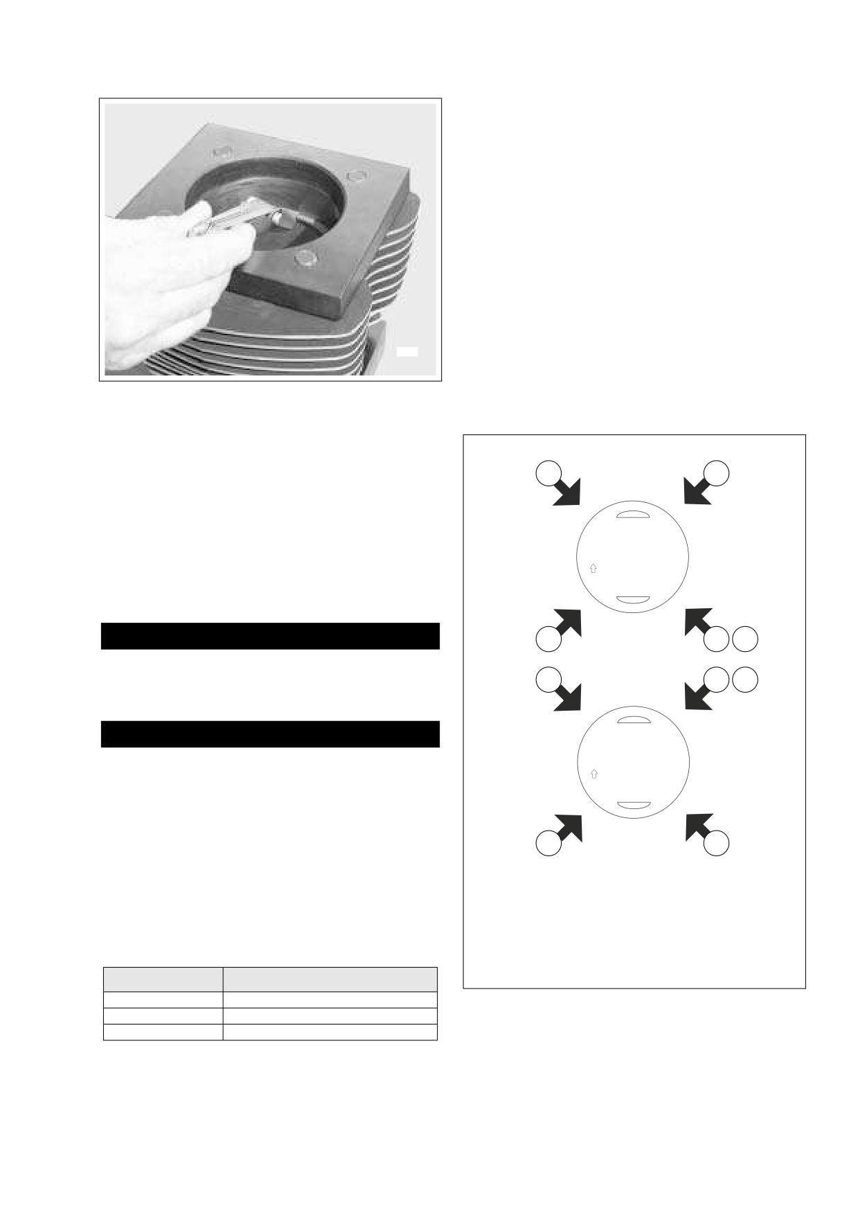
Figure 3-90. Piston Ring Gap Alignment
2nd compression ring
0.014 in. (0.36 mm) - 0.024 in. (0.61 mm)
Oil control ring rails
0.010 in. (0.25 mm) - 0.050 in. (1.27 mm)
2006 Touring: Engine
3-73
HOME
Installation
CAUTION
1.
See Section 3.9 TOP END OVERHAUL, ASSEMBLY,
Use the proper piston ring spreader to prevent excessive
steps 1-24 and 29-39.
ring twist and expansion. Over expansion may cause the
ring to crack opposite the ring gap. Damaged or dis-
torted rings result in blow-by of exhaust gases,
increased oil consumption and lower service life on
valves and other components.
CAUTION
Installing the second compression ring upside down will
cause oil to be scraped up into the combustion chamber
resulting in excessive oil consumption and low service
life on valves and other components.
c. Using the proper piston ring expander (Snap-On
PRS8), carefully install the second compression
ring making sure that the dot (punch mark) near the
ring gap faces the piston crown. Rotate the ring so
the gap is 90 degrees from the gap in the top oil rail.
d. Carefully install the top compression ring using the
proper piston ring expander
(Snap-On PRS8).
Rotate the ring so the gap is 180 degrees from the
gap in the second compression ring.
e. Rotate the three piston rings using the palms of
both hands. The rings must rotate freely without
sticking.
f.
Verify that the ring gaps are still properly staggered.
See Figure 3-90.
3-74
2006 Touring: Engine
HOME
NOTES
2006 Touring: Engine
3-75
HOME
UPPER CONNECTING ROD
Removal
1.
See Section 3.9 TOP END OVERHAUL, DISASSEM-
BLY, steps 1-11 and 15-29.
Disassembly/Assembly
Threaded
NOTE
Cylinders
Service of connecting rods is limited to replacement of the
Part No. HD-95952-1
upper bushing. Damage to connecting rods or lower bushing
service requires replacement of the flywheel assembly.
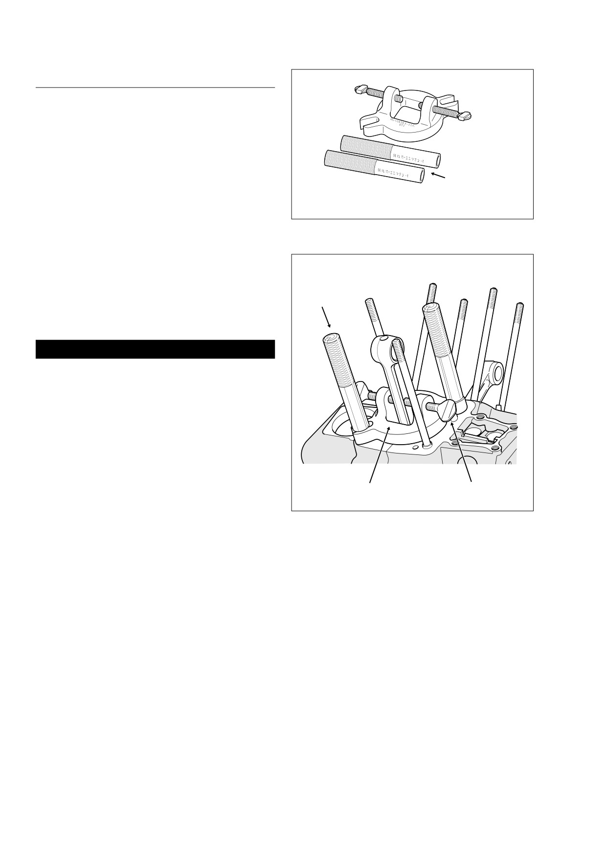
Figure 3-91. Connecting Rod Clamping Tool
(Part No. HD-95952-33B)
Upper Connecting Rod Bushing
f1597x3x
Removal
Threaded
NOTE
Cylinder
Replace the upper rod bushing if the piston pin to rod bush-
ing clearance exceeds 0.002 inch (0.051 mm).
CAUTION
Place clean shop towels in and around the crankcase
bore to prevent chips and shavings from falling into the
crankcase.
1.
Obtain the CONNECTING ROD CLAMPING TOOL (HD-
95952-33B) and proceed as follows:
a. Slide clamp over connecting rod so that slots
engage cylinder head studs. See Figure 3-92. Exer-
cise caution to avoid scratching or bending studs.
b. With the knurled side up, install threaded cylinders
(HD-95952-1) onto studs to secure position of
Clamp
Thumbscrew
clamp.
c. Alternately turn each clamp thumbscrew a few turns
to gradually fix position of connecting rod. Turning
Figure 3-92. Install Connecting Rod Clamping Tool
only one thumbscrew will move rod off-center, while
tightening second thumbscrew can cause rod to flex
f.
Thread the hex cylinder onto rod until assembly is
or bend.
snug. See upper frame of Figure 3-94.
2.
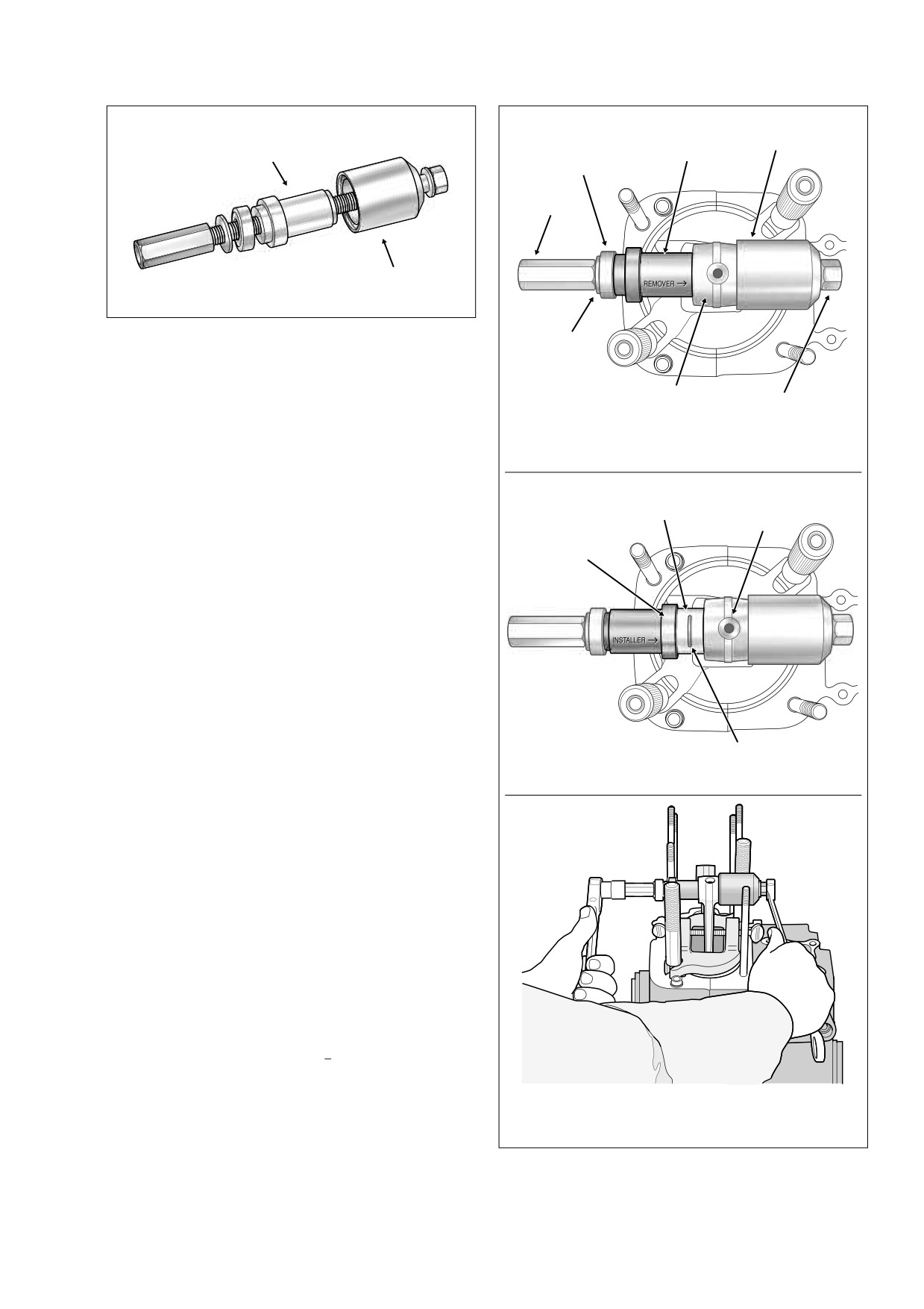
Obtain the CONNECTING ROD BUSHING REMOVER/
INSTALLER (HD-95970-32D) and proceed as follows:
g. Holding nut at end of threaded rod with a 5/8 inch
box wrench, turn hex cylinder with a 5/8 inch socket
a. Sparingly apply graphite lubricant to threads of rod
until bushing is free.
to prolong service life and ensure smooth operation.
h. Unthread hex cylinder from rod. Remove flat
b. Slide receiver cup (HD-95984-99) onto threaded rod
washer, Nice bearing and driver. Remove threaded
with the closed side facing hex nut.
rod from bushing bore.
c. Insert threaded rod through upper rod bushing.
i.
Remove bushing from receiver cup and discard.
d. Slide remover side of driver (HD-95986-99) down
threaded rod. The driver is stamped to ensure
Installation
proper orientation.
e. Slide Nice bearing and flat washer down threaded
1.
Obtain the CONNECTING ROD BUSHING REMOVER/
rod until it contacts driver.
INSTALLER (HD-95970-32D) and proceed as follows:
3-76
2006 Touring: Engine
HOME
Receiver
Driver
Driver
Cup
Remover Side
Part No. HD-95986-99
Nice
Bearing
Hex
Cylinder
Receiver Cup
Part No. HD-95984-99
Figure 3-93. Connecting Rod Bushing Remover/Installer
Flat
(Part No. HD-95970-32D)
Washer
a. Slide receiver cup (HD-95984-99) onto threaded rod
Connecting
Threaded
with the closed side facing hex nut.
Rod
Rod
b. Insert threaded rod through upper rod bushing bore.
Remover Stackup
c. Slide new bushing down threaded rod. Start bush-
f1601x3x
ing into bore. Verify that center of slot in bushing is
aligned with oil hole at top of rod. Also, be sure that
f1602x3x
Upper Rod
bushing is square in bore and not cocked. See cen-
Bushing
ter frame of Figure 3-94.
Oil Hole
Driver
d. Slide installer side of driver (HD-95986-99) down
Installer Side
threaded rod until shoulder contacts bushing. The
driver is stamped to ensure proper orientation.
e. Slide Nice bearing and flat washer down threaded
rod until it contacts driver.
f.
Thread the hex cylinder onto rod until assembly is
snug.
g. Holding nut at end of threaded rod with a 5/8 inch
box wrench, turn hex cylinder with a 5/8 inch socket
until collar on driver bottoms against connecting
rod. See lower frame of Figure 3-94.
Slot
h. Unthread hex cylinder from rod and remove flat
Installer Stackup
washer, Nice bearing and driver. Remove threaded
rod from bushing bore, but exercise caution to avoid
scratching or gouging bushing.
f1598x3x
Reaming Upper Rod Bushing
1.
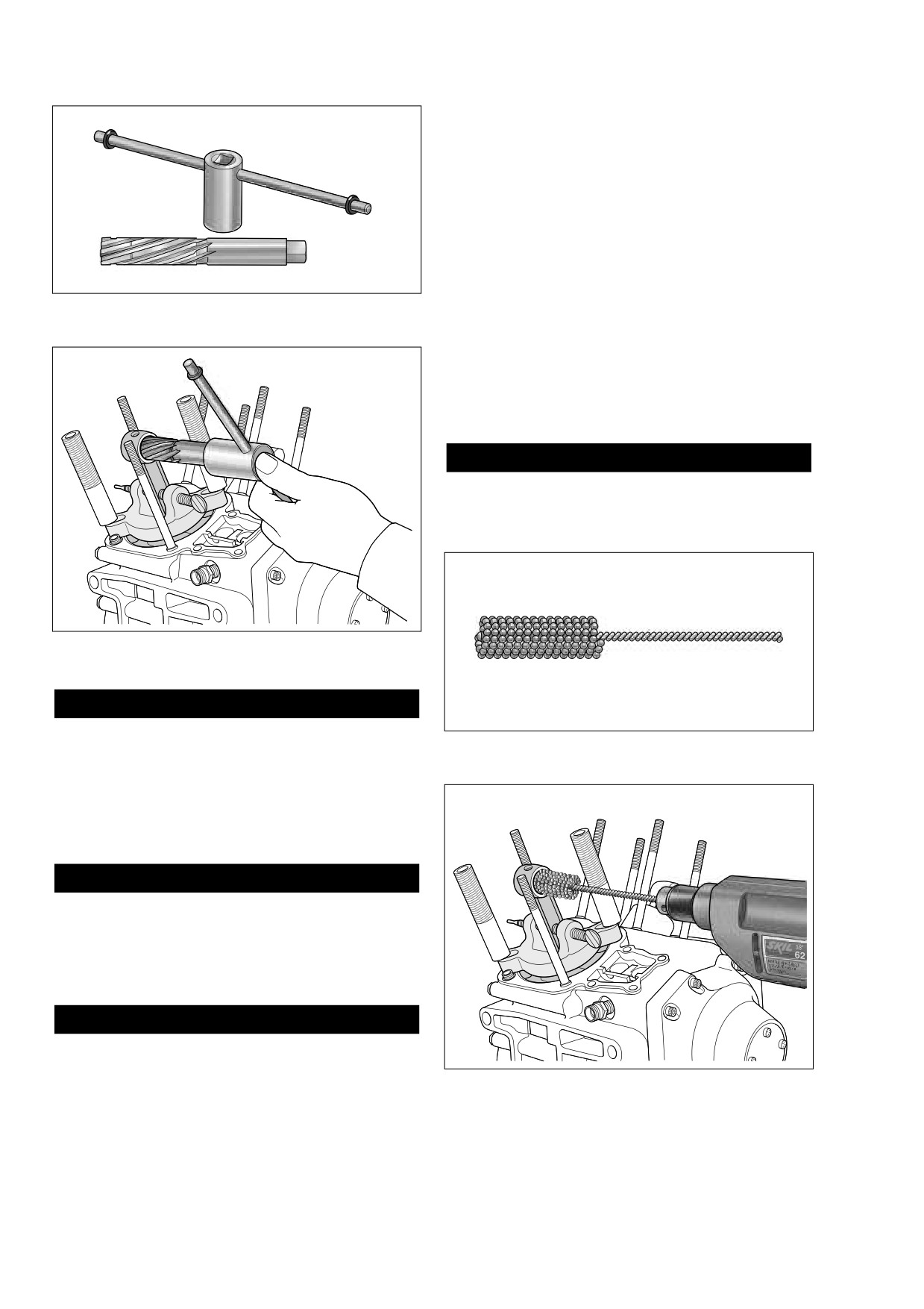
Obtain the CONNECTING ROD BUSHING REAMER
(HD-42318) and REAMER HANDLE/DRIVE SOCKET
(HD-43645). Proceed as follows:
a. Carefully insert bit of reamer into upper connecting
rod bushing. Do not apply lubricant to reamer or
bushing. Ream the bushing dry or cut will not be
accurate.
b. Install handle/drive socket on reamer lug. See Fig-
ure 3-96.
c. Placing thumb on drive socket, apply slight pressure
on reamer while rotating handle/drive socket in a
clockwise direction.
Hold hex nut on threaded rod with 5/8 inch box.
Turn cylinder hex with 5/8 inch socket.
Figure 3-94. Remove/Install Connecting Rod Bushing
2006 Touring: Engine
3-77
HOME
2.
Using contact cleaner or cleaning solvent, thoroughly
wipe upper connecting rod and bushing of any metal
Handle/Drive Socket
shavings or debris.
Honing Upper Rod Bushing
Reamer
1.
Obtain the CONNECTING ROD BUSHING HONE (HD-
42569) and REAMER LUBRICANT (HD-39964). Pro-
ceed as follows:
a. Install hone in a high speed electric drill.
b. Apply reamer lubricant to finishing stones of hone
Figure 3-95. Connecting Rod Bushing Reamer (Part No.
and inside of upper connecting rod bushing.
HD-42318) and Handle/Drive Socket (Part No. HD-43645)
c. Start finishing stones of hone into bushing.
d. Activating the drill, move the entire length of the fin-
f1642x3x
ishing stone arrangement forward and backward
through the bushing bore for 10 to 12 complete
strokes. See Figure 3-98. Work for a crosshatch
pattern of approximately 60˚.
CAUTION
Abrasive particles can damage machined surfaces and
plug oil passageways possibly resulting in engine fail-
ure.
Figure 3-96. Ream Connecting Rod Bushing
CAUTION
For best results, do not push on reamer or apply pres-
Figure 3-97. Connecting Rod Bushing Hone
sure to the reamer handle. While excessive pressure
(Part No. HD-42569)
results in a rough cut, bushing bore will be tapered if
pressure is not centrally applied.
f1643x3x
d. Continue rotating handle/drive socket until entire bit
has passed through bushing and shank of reamer
rotates freely in the bore.
CAUTION
Never back reamer out of connecting rod or bushing will
be damaged.
e. Remove handle/drive socket, and carefully pulling
on bit, draw shaft of reamer out of connecting rod
bushing.
CAUTION
Abrasive particles can damage machined surfaces and
plug oil passageways possibly resulting in engine fail-
ure.
Figure 3-98. Hone Connecting Rod Bushing
3-78
2006 Touring: Engine
HOME
2.
Using contact cleaner or cleaning solvent, thoroughly
Installation
wipe upper connecting rod and bushing of any metal
shavings or debris. Continue wiping until a clean cloth
See Section 3.9 TOP END OVERHAUL, ASSEMBLY, steps
shows no evidence of dirt or debris.
1-24 and 29-39.
3.
Lightly oil a good piston pin and insert it into the upper
connecting rod bushing bore to feel for the proper inter-
ference fit. The pin should slide in and out of the bushing
without binding, but also without pivoting or rocking.
4.
Remove shop towels exercising caution that shavings,
chips and other debris do not fall into crankcase.
2006 Touring: Engine
3-79
HOME
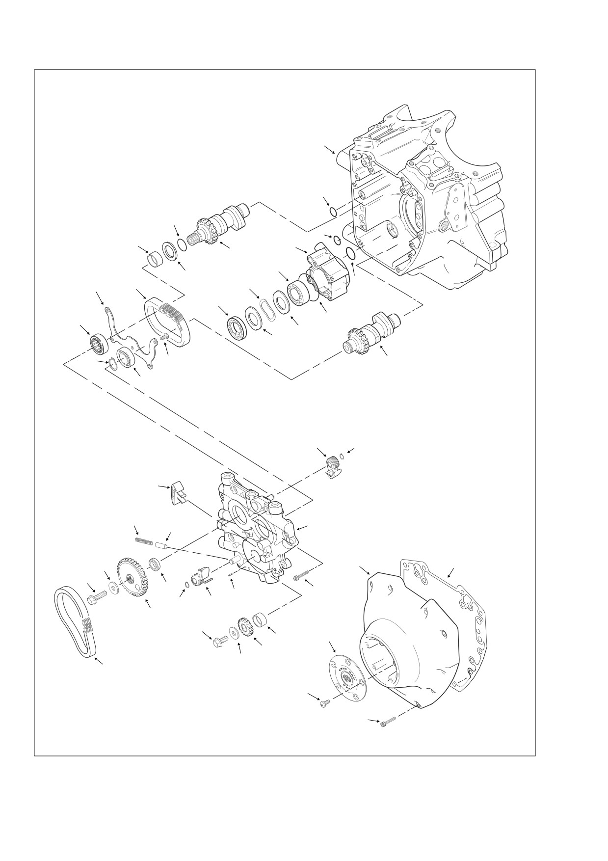
Legend:
1.
T20 TORX Screw
17. Roll Pin
2.
Cam Position Sensor Cover
18. Oil Pressure Relief Valve Piston
3.
Screw
19. Valve Spring
4.
Cam Cover
20. Chain Guide
5.
Cam Cover Gasket
21. Screw
6.
Primary Cam Chain
22. Cam Support Plate
45
7.
Flange Bolt
23. Secondary Cam Chain Tensioner
8.
Flat Washer
24. Retaining Ring
9.
Primary Cam Sprocket
25. Retaining Ring
10.
Spacer
26. Rear Cam (Roller) Bearing
11.
Retaining Ring
27. Front Cam (Ball) Bearing
12.
Primary Cam Chain Tensioner
44
13.
Flange Bolt
14.
Flat Washer
15.
Crank Sprocket
16.
Crankshaft Bushing
33
43
31
41
34
39
32
42
28
30
38
36
40
26
37
37
25
29
35
27
28.
Bearing Retainer Plate
29.
T20 TORX Screw
30.
Secondary Cam Chain
31.
Roller Bearing Inner Race
32.
Thrust Washer
33.
O-Ring
34.
Rear Camshaft
23
35.
Front Camshaft
24
36.
Feed Gerotor Set
37.
Separator Plate
38.
Wave Washer
39.
Scavenge Gerotor Set
40.
O-Ring
20
41.
Oil Pump Housing
42.
O-Ring (Scavenge Port Stub)
43.
O-Ring (Oil Feed Hole)
44.
O-Ring (Blind Hole)
19
45.
Right Crankcase Half
22
18
4
5
8
7
10
21
17
12
11
9
13
16
2
15
14
6
1
3
f2413x3x
Figure 3-99. Cam Support Plate/Oil Pump Assemblies (Exploded View)
3-80
2006 Touring: Engine
HOME
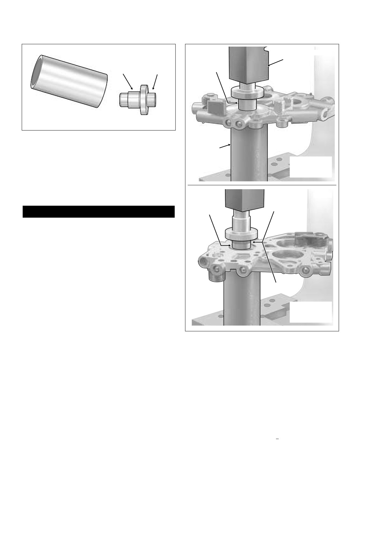
2.
Center support tube under ram of arbor press.
BOTTOM END
3.
Center crankshaft bushing in cam support plate over
support tube. Be sure that the primary cam chain side of
the cam support plate is facing upward.
CAM SUPPORT PLATE
CAUTION
Removal
If the crankshaft bushing is pressed out the primary cam
1.
See Section 3.9 TOP END OVERHAUL, DISASSEM-
chain side, the bore will be damaged by the knurled edge
BLY, steps 1-11.
of the bushing. Damage to the bore requires replace-
ment of the cam support plate.
NOTE
When removing the cam support plate, it is not necessary to
4.
Insert remover side of driver into crankshaft bore so that
disturb the lifter assemblies if a method is devised to prevent
shoulder on tool is seated on edge of bushing. See
the hydraulic lifters from dropping into the cam compartment.
upper frame of Figure 3-102.
One such method is provided in the following step. Leaving
5.
Press on driver until collar of tool contacts cam support
the lifter assemblies intact simplifies the procedure, since the
plate. Remove bushing from support tube and discard.
lifter cover, gasket, anti-rotation pin and hydraulic lifters can
be left in place.
Installation
2.
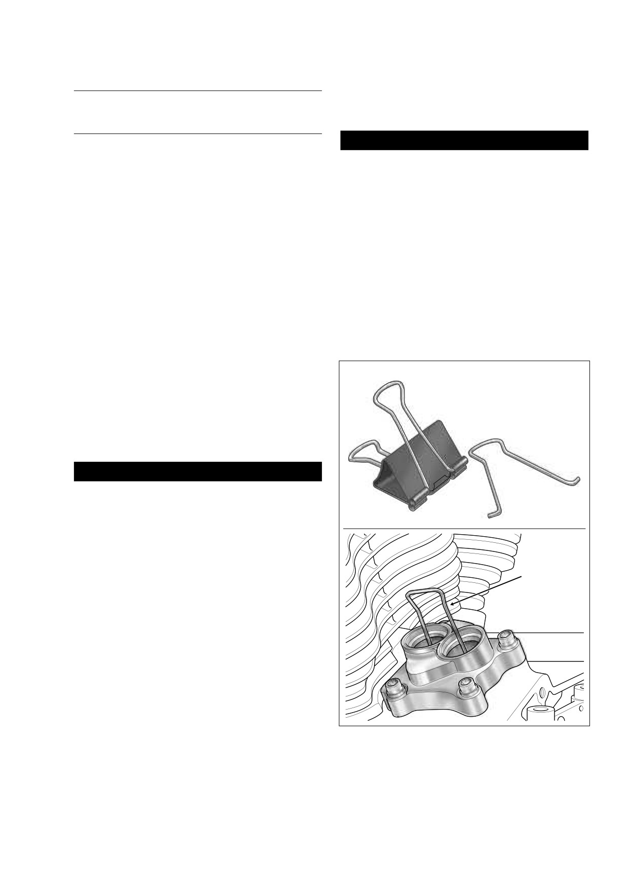
Fashion lifter holding tool as follows:
1.
Obtain the CRANKSHAFT BUSHING REMOVER/
a. Obtain a large binder clip (available at any office
INSTALLER (HD-42315).
supply store). Squeeze wireforms to remove from
2.
Center support tube under ram of arbor press.
binder clip. See upper frame of Figure 3-100.
b. Compress wireform slightly and insert free ends into
outer and inner lifter cover bores so that legs
engage walls of both hydraulic lifter sockets. See
f1596x3x
lower frame of Figure 3-100.
Binder Clip
3.
See Section 3.10 BOTTOM END OVERHAUL, DISAS-
SEMBLY, steps 1-14.
Wireform
Disassembly/Assembly
1CAUTION
Do not pull the retention pins from the primary or sec-
ondary cam chain tensioners with the chains and
sprockets removed. With 35-40 pounds of spring pres-
sure behind the tensioner, allowing it to accelerate
through its full length of travel will cause spring stretch-
f1595x3x
ing and/or cracking of the tensioner shoe, damage which
requires replacement of the assembly. Furthermore, if
the tensioner should contact fingers or other parts of the
Wireform
hand, minor or moderate injury may occur.
NOTE
If the retention pins interfere with cleaning or service proce-
dures, hold the retracted cam chain tensioner with the CAM
CHAIN TENSIONER UNLOADER (HD-42313), pull the
retention pin and ease the assembly into the unloaded posi-
tion.
Crankshaft Bushing
Removal
1.
Obtain the CRANKSHAFT BUSHING REMOVER/
INSTALLER (HD-42315).
Figure 3-100. Fashion Tool to Hold Hydraulic Lifters
2006 Touring: Engine
3-81
HOME
f1599x3x
Ram
Driver
Remover
Installer
Remover Side
Side
Side
Down
Support
Tube
Driver
Figure 3-101. Crankshaft Bushing Remover/Installer
(Part No. HD-42315)
Support
Tube
REMOVE
3.
Turn cam support plate over so that secondary cam
CRANKSHAFT
chain side is facing upward.
BUSHING
4.
Start new bushing into bore with the knurled edge top-
side. Be sure that hole in bushing is aligned with oil hole
in bushing bore.
Crankshaft
f1600x3x
Driver
Bushing
Installer Side
Knurled Side Up
Down
CAUTION
If the crankshaft bushing is pressed in from the primary
cam chain side, or from the secondary cam chain side
with the knurled edge of the bushing down, the bushing
bore will be damaged. Damage to the bore requires
replacement of the cam support plate.
5.
Center crankshaft bushing bore over support tube.
6.
Insert installer side of driver into bushing. See lower
frame of Figure 3-102.
Ensure Oil
Hole Alignment
7.
Press on driver until collar of tool makes firm contact
with cam support plate.
INSTALL
8.
Ream the crankshaft bushing following the directions
CRANKSHAFT
below.
BUSHING
Figure 3-102. Remove/Install Crankshaft Bushing
Reaming Crankshaft Bushing
in Cam Support Plate
NOTE
A new crankshaft bushing must be reamed for proper size
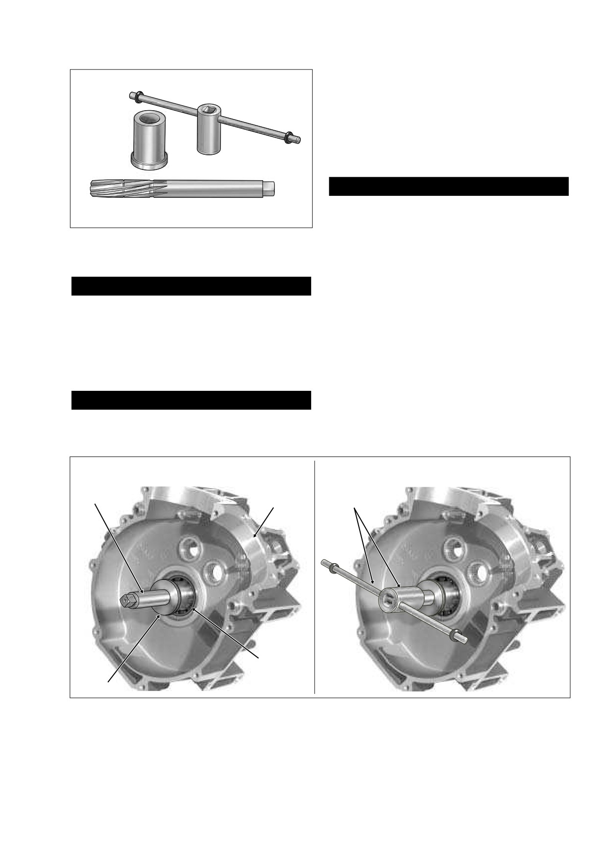
a. From flywheel compartment side, carefully insert
and alignment. If crankcase halves are not split, ream the
tapered end of reamer pilot into crankshaft bearing
bushing using a spare right case half to avoid further engine
until it stops. See left frame of Figure 3-104.
disassembly.
b. Slide reamer through pilot starting bit into crank-
1.
Slide cam support plate onto two ring dowels in crank-
shaft bushing in cam support plate. Do not apply
case flange.
lubricant to reamer or bushing. Ream the bushing
dry or cut will not be accurate.
2.
Install six allen head socket screws (1/4 x 1 inch) to
secure cam support plate to crankcase flange. Alter-
c. Install handle/drive socket on reamer lug. See right
nately tighten screws until snug.
frame of Figure 3-104.
3.
Obtain the CRANKSHAFT BUSHING REAMER (HD-
d. Placing thumb on drive socket, apply slight pressure
42316) and REAMER HANDLE/DRIVE SOCKET (HD-
on reamer while rotating handle/drive socket in a
43645). Proceed as follows:
clockwise direction.
3-82
2006 Touring: Engine
HOME
f.
Remove handle/drive socket, and carefully pulling
Handle/Drive Socket
on bit, draw shaft of reamer out of bushing on cam
side of crankcase.
g. Remove pilot from crankshaft bearing. Tap on pilot
Pilot
using a soft rubber mallet, if necessary.
4.
Remove the allen head socket screws to release the
cam support plate from the crankcase flange.
CAUTION
Abrasive particles can damage machined surfaces and
Reamer
plug oil passages possibly resulting in engine failure.
Figure 3-103. Crankshaft Bushing Reamer (Part No. HD-
5.
Thoroughly flush right crankcase half and cam support
42316) and Handle/Drive Socket (Part No. HD-43645)
plate in cleaning solvent to remove any metal shavings
or debris. Blow dry with compressed air.
CAUTION
Camshafts/Camshaft Bearings
For best results, do not push on reamer or apply pres-
sure to the reamer handle. While excessive pressure
Removal
results in a rough cut, bushing bore will be tapered if
1.
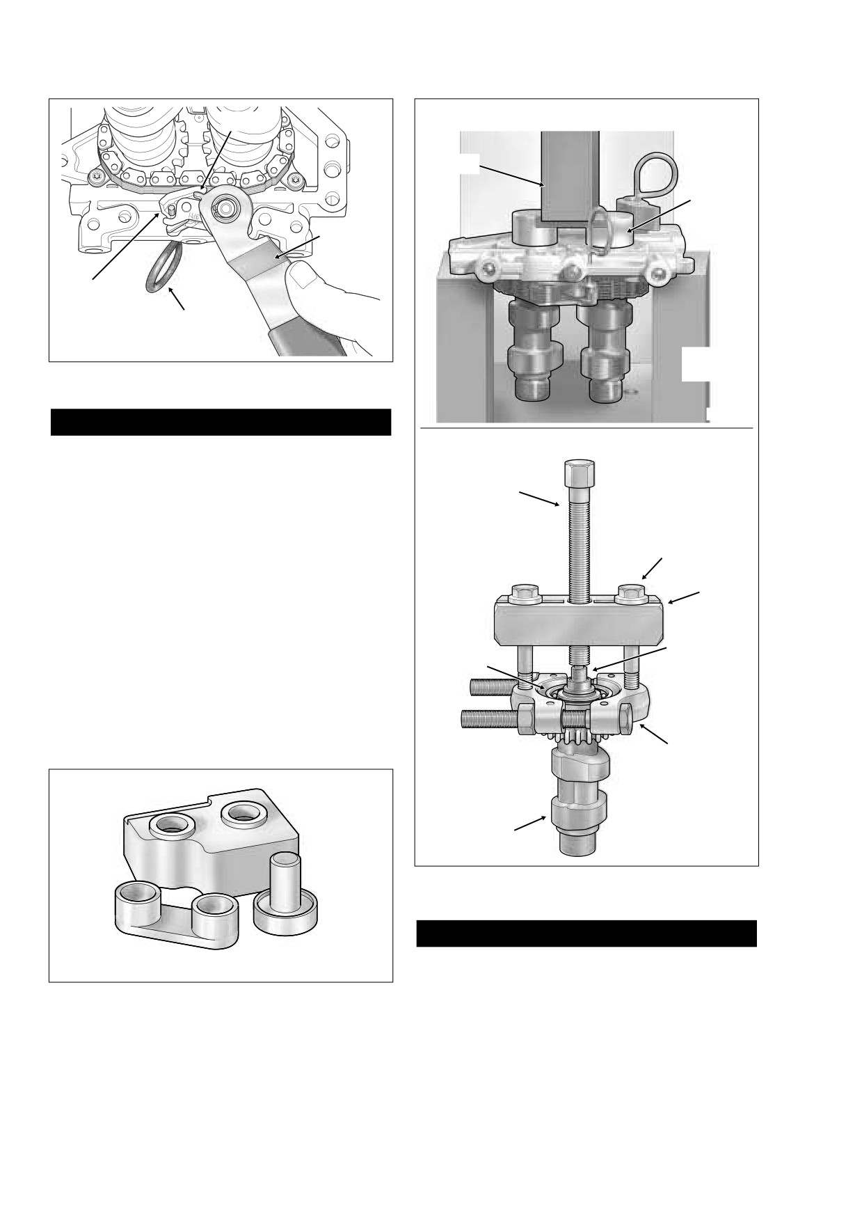
Place cup of CAM CHAIN TENSIONER UNLOADER
pressure is not centrally applied.
(HD-42313) over spring coil of secondary cam chain ten-
e. Continue rotating handle/drive socket until entire bit
sioner positioning finger on tool between tensioner and
has passed through bushing and shank of reamer
shoe. See Figure 3-105. Rotate tool in a counterclock-
rotates freely in the bore.
wise direction inserting retention pin through hole in
boss on primary cam chain side of cam support plate.
Pin engages hooks on tensioner to hold it in the
CAUTION
retracted position. For best results, place cam support
Never back reamer out flywheel side of crankcase or
plate in a vise using brass jaw inserts to prevent casting
crankshaft bushing will be damaged.
damage.
Install pilot and reamer from flywheel side of case.
Install handle/drive socket on reamer.
Right Crankcase
Handle/
Reamer
Half
Drive Socket
Crankshaft
Bearing
Pilot
f1619x3x
f1611x3x
Figure 3-104. Ream Crankshaft Bushing
2006 Touring: Engine
3-83
HOME
Press out camshafts (with bearings).
Finger
Ram
Camshaft
Driver
Tensioner
Shoe
Retention
Pin
f1637b3x
Parallel
Figure 3-105. Retract Secondary Cam Chain Tensioner
Blocks
f1623x3x
1WARNING
Remove bearing from front camshaft.
Always wear proper eye protection when removing re-
taining rings. Use the correct retaining ring pliers. Verify
that the tips of the pliers are not damaged or excessively
Forcing
worn. Slippage may propel the ring with enough force to
Screw
cause eye injury.
3/8-16 Inch
2.
Remove retaining ring from groove at end of front cam-
Bolt
shaft. Discard retaining ring.
with Flat Washer
3.
Remove four T20 TORX screws to free bearing retainer
plate from inboard side of cam support plate.
Bridge
4.
Using a colored marker, mark one of the links of the sec-
ondary cam chain. Maintaining the original direction of
rotation during assembly may prolong service life of
Hardened
chain.
Plug
Bearing
5.
With the primary cam chain side facing upward, place
cam support plate on parallel blocks under ram of arbor
press.
6.
Obtain the CAMSHAFT/CAMSHAFT BEARING RE-
MOVER/INSTALLER (HD-43644). See Figure 3-106.
Wedge
Attachment
Support Block
Front
Camshaft
f1611x3x
Figure 3-107. Remove Camshafts/Front Cam Bearing
CAUTION
Camshaft Driver
Bearing Pilot/Driver
Since the bearing fit to the camshafts is tighter than its
fit in the support plate, any attempt to remove the cam-
Figure 3-106. Camshaft/Camshaft Bearing
shafts without the bearings will result in damage to the
Remover/Installer (Part No. HD-43644)
cam support plate and bearing retainer plate, if installed.
3-84
2006 Touring: Engine
HOME
f1806x3x
Pull Bearing Inner Race and Thrust Washer
A
From Rear Cam. Remove O-Ring if Present.
Thrust
Washer
Inner
Shop
Race
Rag
Box Wrench
5/8 Inch
NOTE
Although the vane has been eliminated
from the cam sprocket on production
motorcycles, the service part retains the
vane to retrofit earlier models having a
camshaft position sensor.
Box Wrench
Inner
9/16 Inch
Race
Shop
Thrust
Rag
Washer
Install O-Ring and Thrust Washer.
B
Press Bearing Inner Race Onto Rear Cam.
f1807x3x
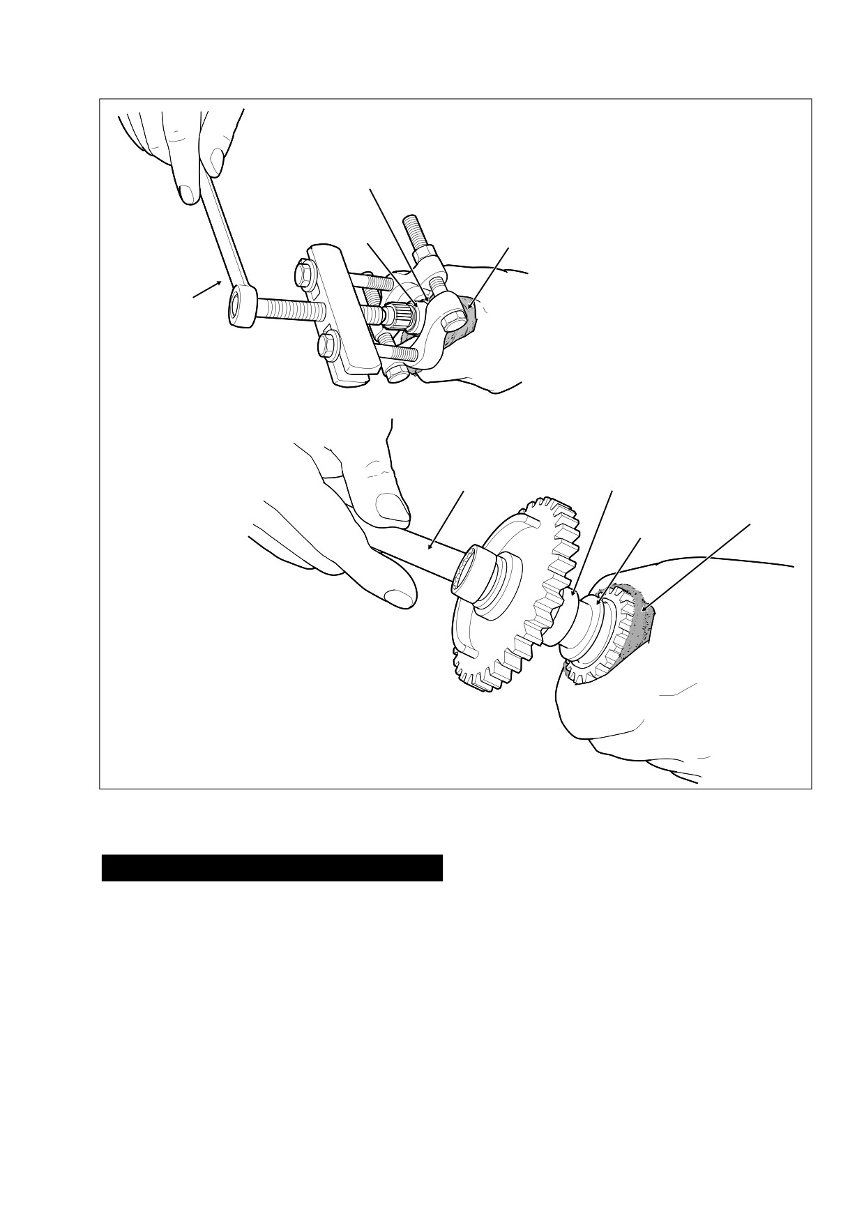
Figure 3-108. Remove/Install Bearing Inner Race (With O-Ring and Thrust Washer) Onto Rear Camshaft
CAUTION
camshafts (with attached bearings) from the cam sup-
port plate. See upper frame of Figure 3-107.
Cam bearings may be a loose fit in the cam support
plate. To avoid possible damage, be aware that camshaft
8.
Remove secondary cam chain from cam sprockets.
and bearing assemblies may drop out at start of press
9.
If reusing front camshaft, remove bearing as follows:
procedure.
7.
Fit cups of camshaft driver over ends of front and rear
a. Position WEDGE ATTACHMENT (HD-95637-46B)
camshafts, so that contact is made with the bearing
on inboard side of front camshaft bearing and turn
inner races. Centering driver under ram at a point mid-
hex nuts an equal number of turns to draw halves of
way between the camshafts, simultaneously press both
wedge together.
2006 Touring: Engine
3-85
HOME
b. Obtain two 3/8-16 inch bolts 3-1/2 inches long (with
flat washers). Install flat washers on bolts. Obtain
O-Ring
Thrust Washer
bridge, forcing screw and hardened plug from
MAINSHAFT BEARING INNER RACE PULLER/
INSTALLER (HD-34902B).
c. Slide one bolt into channel on each side of bridge
so that flat washer is between bridge and bolt head.
Thread bolts into wedge attachment an equal num-
ber of turns.
d. Sparingly apply graphite lubricant to threads of forc-
ing screw to prolong service life and ensure smooth
operation. Start forcing screw into center hole of
Bearing Inner Race
bridge.
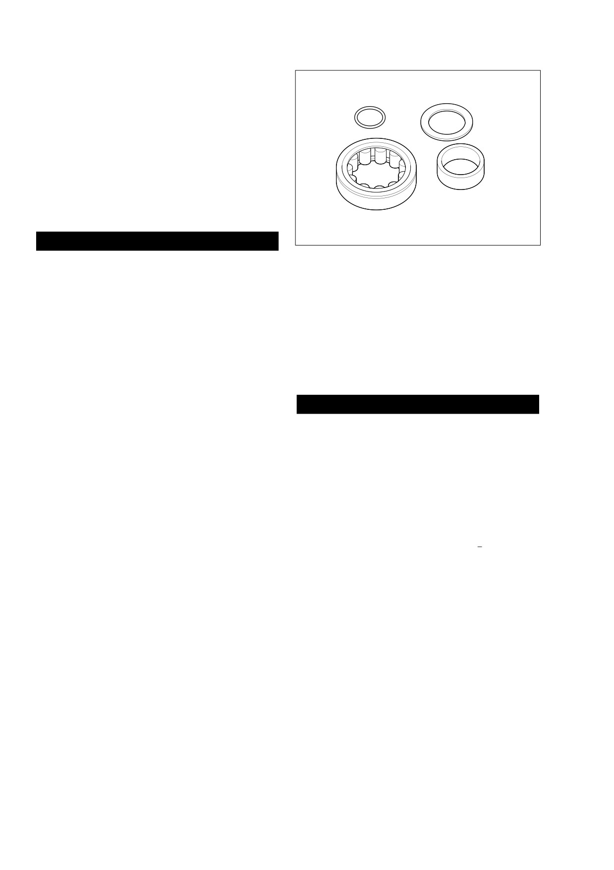
Roller Bearing
f1805x3x
CAUTION
Figure 3-109. Rear Cam Roller Bearing Kit (P/N 8983)
Failure to use hardened plug may result in damage to
forcing screw and/or camshaft.
2.
Install O-ring, thrust washer and bearing inner race onto
e. Place cupped side of hardened plug against end of
rear camshaft as follows:
camshaft. Thread forcing screw into bridge until the
steel ball at the end of the screw makes firm contact
a. To properly locate thrust washer, first install O-ring
with hardened plug.
in grinding relief groove. Groove is on the splined
end between the machined area and the secondary
f.
Verify that the tool assembly is square so that the
cam sprocket. Exercise caution to avoid stretching
bearing is not cocked during removal. See lower
or breaking the O-ring. Since the O-ring is not sold
frame of Figure 3-107. Turn forcing screw until bear-
separately, damage will require purchase of a new
ing is pulled free of camshaft. Discard bearing.
roller bearing kit.
10.
If reusing rear camshaft, remove roller bearing assembly
as follows:
CAUTION
a. Slide roller bearing from end of rear camshaft.
Since bearing is a loose fit on cam, no pressing
The thrust washer will be offset to one side if the O-ring
tools are required.
is not installed in the grinding relief groove. Damage to
the bearing cage can occur if the thrust washer is not
b. Install tools as you would to remove the bearing
properly centered.
from the front camshaft, but position cup of wedge
inboard of the thrust washer.
b. Slide thrust washer down rear camshaft until cen-
c. Wrap a shop rag around camshaft to get a firm grip
tered over O-ring in grinding relief groove.
and also to protect hand from sharp edges of
c. Slide bearing inner race down rear camshaft until
sprocket.
contact is made with shoulder of machined area.
d. Using a 5/8 inch box wrench, turn forcing screw until
d. Install primary cam sprocket spacer and sprocket
bearing inner race and thrust washer are pulled free
on camshaft and secure using thicker flat washer
of camshaft. See A of Figure 3-108. A light interfer-
and long flange bolt.
ence fit allows the parts to be removed with little
effort. Discard inner race and thrust washer.
NOTE
e. If present, remove O-ring from grinding relief groove
If not enough of the splined shaft is exposed to install the
in camshaft. Groove is on the splined end between
sprocket, leave out the spacer and proceed to step 2(e).
the machined area and the secondary cam
Once the bearing inner race has been started onto the
sprocket. Discard O-ring.
machined area, remove the flange bolt, washer and sprocket,
and then reassemble using the spacer. Repeat step 2(e) to
NOTE
fully install bearing inner race.
Since the O-ring is not used in production, it will only be
found if the cams were serviced at the dealer level.
e. Wrap a shop rag around camshaft to get a firm grip
and also to protect hand from sharp edges of
sprocket. Using a 9/16 inch box wrench, turn flange
Installation
bolt in a clockwise direction. Bearing inner race is
1.
Obtain new rear cam roller bearing kit (Part No. 8983).
fully installed when it makes firm contact with the
See Figure 3-109.
thrust washer. See B of Figure 3-108.
3-86
2006 Touring: Engine