Harley Davidson FLHRC 2006. Maintenance & Repair Manual - page 13
HOME
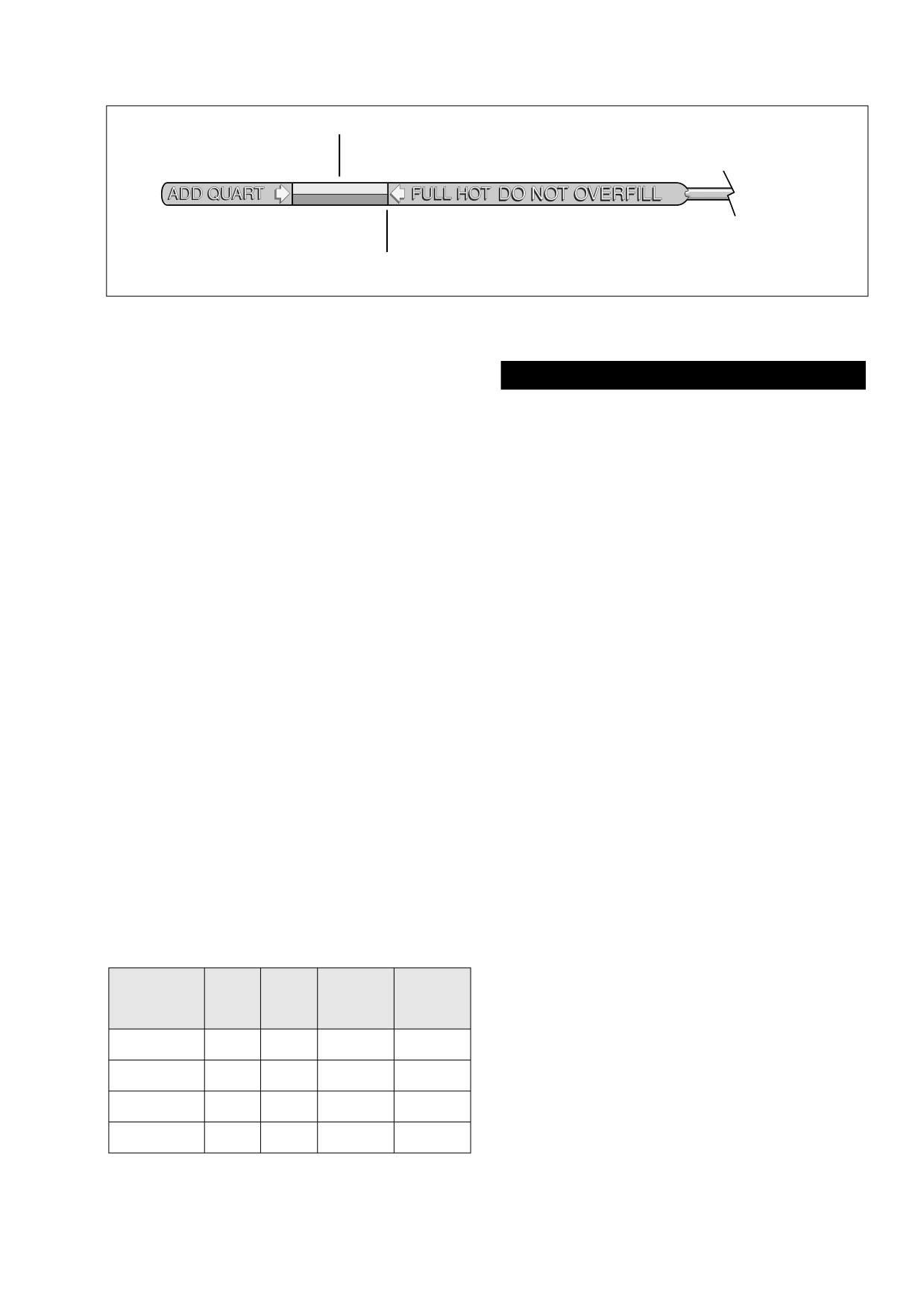
COLD CHECK
HOT CHECK
f1254b3x
Figure 3-19. Engine Oil Dipstick
d. Moving to left side of motorcycle, install ET sensor
connector [90] at back of front cylinder. Pull boot
CAUTION
over sensor to keep out dirt and debris. Install new
Oil level cannot be accurately measured on a cold
cable strap to secure connector conduit to horn
engine. For preride inspection, with motorcycle leaning
bracket.
on jiffy stand on level ground, oil should register on dip-
42.
Install the primary chaincase. See Section
6.5 PRI-
stick between arrows when engine is cold. Do NOT add
MARY CHAINCASE, INSTALLATION.
oil to bring the level to the FULL mark on a COLD engine.
43.
Install the fuel tank. Proceed as follows:
48.
Perform engine oil level COLD CHECK as follows:
Carbureted: See Section 4.7 FUEL TANK (CARBU-
RETED), INSTALLATION
(AFTER COMPLETE
a. With the motorcycle resting on the jiffy stand on
REMOVAL), FLHX, FLHT, or FLHR/S.
level ground, wipe off the dipstick and insert it back
Fuel Injected: See Section
9.4 FUEL TANK (FUEL
into the oil pan with the plug pushed completely into
INJECTED), INSTALLATION
(AFTER COMPLETE
the fill spout.
REMOVAL), FLHXI, FLHT/C/U/I, FLTRI, or FLHR/C/S/I.
b. Remove the dipstick and note the level of the oil. Oil
level should register between the two arrows on the
44.
Adjust idle and throttle control cables as follows:
dipstick. See Figure 3-19. If oil level is at or below
Non-Cruise: See Section 2.21 THROTTLE CABLES
the lower arrow, add only enough oil to bring the
(NON-CRUISE), ADJUSTMENT.
level between the two arrows on the dipstick.
Cruise Equipped: See Section 8.31 CRUISE CON-
TROL (FLHRC, FLHTCU, FLTR), CABLE ADJUST-
49.
Perform engine oil level HOT CHECK as follows:
MENT.
45.
Install the backplate and air cleaner. See Section 4.5
a. Ride motorcycle until engine is at normal operating
AIR CLEANER, INSTALLATION.
temperature.
46.
Install the exhaust system. See Section 2.38 EXHAUST
b. With the motorcycle resting on the jiffy stand on
SYSTEM, INSTALLATION.
level ground, allow engine to idle for 1-2 minutes.
Turn engine off.
NOTE
If oil pan was not drained, move to step 48.
c. Wipe off the dipstick and insert it back into the oil
pan with the plug pushed completely into the fill
47.
With motorcycle resting on jiffy stand, add 3-1/2 quarts
spout.
(3.3 liters) engine oil as specified in Table 3-2. Use the
proper grade of oil for the lowest temperature expected
d. Remove the dipstick and note the level of the oil.
before the next oil change.
Add only enough oil to bring the level to the FULL
mark on the dipstick. See Figure 3-19. Do not over-
Table 3-2. Recommended Engine Oils
fill.
Harley-
Lowest
Cold Weather
Harley-Davidson
50.
Start engine and carefully check for oil leaks around
Viscosity
Davidson
Ambient
Starts Below
Type
drain plug and oil filter.
Rating
Temperature
50˚F (10˚C)
SAE
Below 40˚F
HD Multi-grade
HD 360
Excellent
10W40
(4˚C)
SAE
Above 40˚F
HD Multi-grade
HD 360
Good
20W50
(4˚C)
SAE
Above 60˚F
HD Regular Heavy
HD 360
Poor
50
(16˚C)
SAE
Above 80˚F
HD Extra Heavy
HD 360
Poor
60
(27˚C)
2006 Touring: Engine
3-27
HOME
NOTES
3-28
2006 Touring: Engine
HOME
TOP END OVERHAUL
3.9
DISASSEMBLY
1.
Use low pressure spray to thoroughly clean exterior sur-
faces of engine prior to disassembly. Dirt caked on cool-
ing fins and other areas can fall into crankcase bore or
stick to subassemblies as parts are removed. Abrasive
particles can damage machined surfaces or plug oil pas-
sageways.
NOTE
It is assumed that each step performed on one cylinder is
automatically repeated on the other.
2.
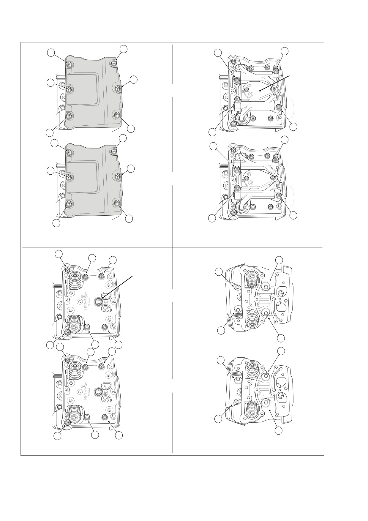
Alternately loosen the six rocker cover bolts following the
pattern shown in A of Figure 3-22. Remove the rocker
cover bolts.
NOTE
If the engine is left in the chassis for service, use the
f1603x3x
ROCKER COVER WRENCH (HD-47258) and ROCKER
HOUSING WRENCH (HD-47248) to remove the rocker cover
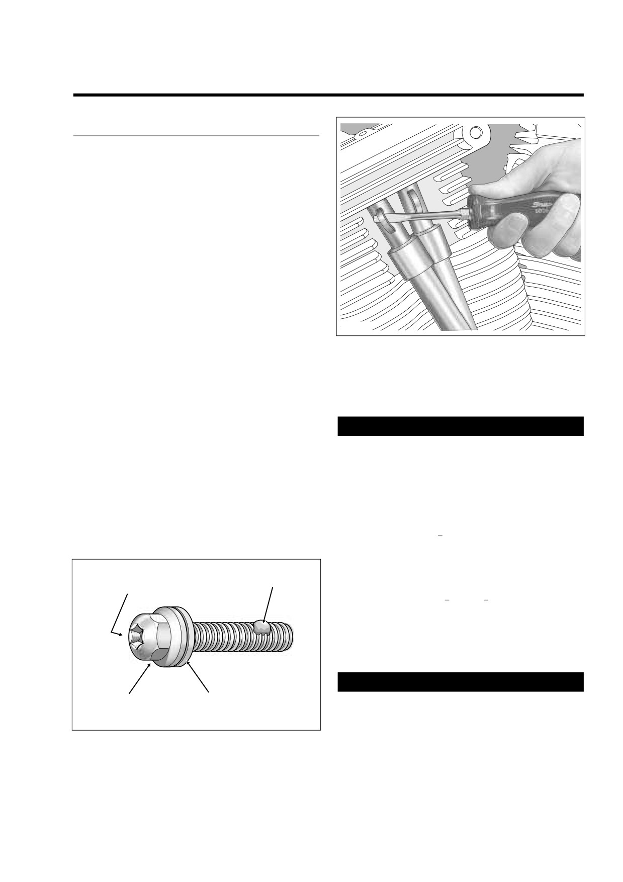
Figure 3-21. Remove Spring Cap Retainer
and rocker housing bolts, respectively. These tools are
especially useful when removing the bolts on the left side of
the engine (particularly the rear) where there is close proxim-
6.
To remove the rocker arm support plate, both lifters of
ity to the frame. With both an external and internal hex, the
the cylinder being serviced must be on the base circle
bolts also can be removed with either a 7/16 inch socket or
(or lowest position) of the cam.
open end/box wrench (open spaces), or a short 3/16 inch
allen wrench (tight spaces). See Figure 3-20.
CAUTION
3.
Remove the rocker cover and gasket. Discard the gas-
Removing the rocker arms with the valve train loaded
ket.
can result in bent push rods, damaged bushings or
4.
Insert the blade of a small screwdriver into cast loop of
warped support plate.
spring cap retainer (at top of upper push rod cover), and
while pushing down on spring cap, rotate bottom of
To find the base circle, it is first necessary to rotate the
screwdriver toward outboard side to remove. See Figure
engine. Based on the level of disassembly required,
3-21. Repeat step on second push rod cover.
three methods of engine rotation are presented below.
5.
Collapse upper and lower push rod covers.
a. With primary cover installed - With vehicle on center
stand, place the transmission in 5th gear and rotate
rear wheel in a clockwise direction (as viewed from
right side) until the base circle is found. See step
Internal Hex
6(d) to find the base circle.
Part No. HD-47258 or
Lock Patch
3/16 Inch Allen Wrench
b. With primary cover removed
- Remove primary
cover. Place the transmission in neutral. Fit a 1-1/2
inch socket on the compensating sprocket shaft nut.
Rotate nut in a counterclockwise direction until the
base circle is found. See step 6(d) to find the base
circle.
CAUTION
External Hex
Captive
Do not attempt to rotate engine by removing cam cover
Part No. HD-47248 or
Washer
7/16 Inch Open End Wrench
and placing socket on crank or primary cam sprocket
f1570x3x
flange bolt. Head of flange bolt can break off possibly
resulting in damage to flywheel or camshaft.
Figure 3-20. Rocker Cover Bolt (1-1/4 Inch)
2006 Touring: Engine
3-29
HOME
4
f2164x3x
5
1
3
f2163x3x
Breather
Assembly
2
1
FRONT
2
6
3
4
6
2
3
4
2
1
REAR
3
4
1
5
Remove Two Breather Assembly Bolts.
Alternately Loosen Four Rocker Arm Bolts
A
Loosen Six Rocker Cover Bolts.
B
1/4 Turn in Pattern Shown.
f2165x3x
2
f2166x3x
6
4
4
2
O-Ring
FRONT
1
3
3
5
1
3
5
1
3
1
REAR
2
4
2
6
4
Alternately Loosen Four Cylinder Head
C
Loosen Six Rocker Housing Bolts.
D
Bolts 1/4 Turn in Pattern Shown.
Figure 3-22. Top End Disassembly
3-30
2006 Touring: Engine
HOME
10.
Remove the intake and exhaust push rods. Tag the push
rods as they are removed, so that they can be installed
in their original locations. Also take note of their orienta-
tion to be able to discern top from bottom at time of
installation.
11.
Remove push rod covers from cylinder head and lifter
cover bores. Remove three O-rings from push rod cov-
ers and discard. If O-ring is missing from upper push rod
cover, be sure to dislodge it from the cylinder head bore.
12.
Using a crosswise pattern, remove the four allen head
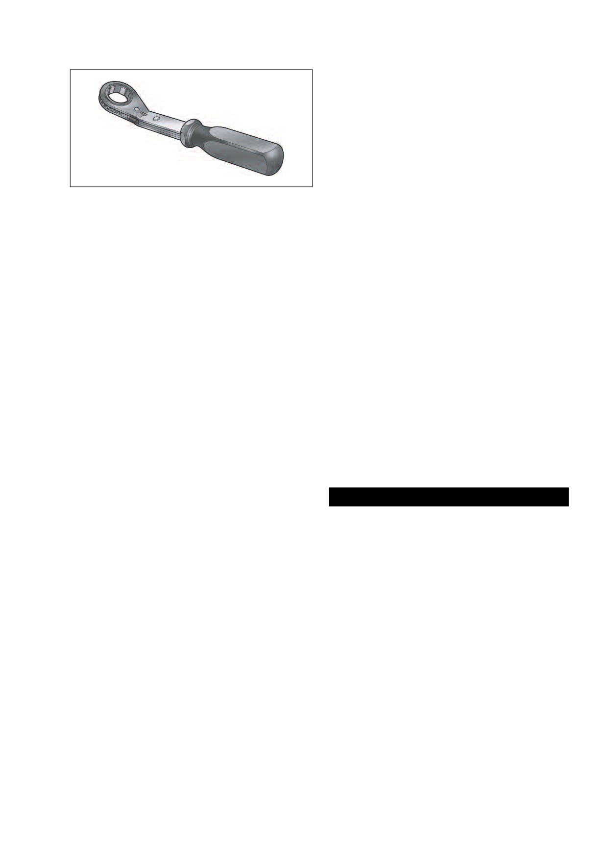
Figure 3-23. Engine Rotation Wrench (Part No. HD-47257)
socket screws to release the lifter cover. Remove the
lifter cover and gasket. Discard the gasket.
13.
Remove the anti-rotation pin. Remove the hydraulic lift-
c. With engine mounted in engine stand - Obtain the
ers. Tag lifters as they are removed, so that they can be
ENGINE ROTATION WRENCH (HD-47257). See
installed in their original locations. Also take note of their
Figure 3-23. Install tool on sprocket shaft and rotate
orientation (by observing location of the oil hole) to be
in a counterclockwise direction until the base circle
able to discern front from rear at time of installation.
is found. See step 6(d) to find the base circle.
14.
Place the lifters in clean plastic bags to keep out dust,
d. Finding the base circle: Using one of the methods
dirt and debris. See Section 3.11 SUBASSEMBLY SER-
above, rotate engine until piston is at Top Dead
VICE AND REPAIR, PUSH RODS/LIFTERS/COVERS.
Center (TDC) of compression stroke. To accomplish
this, first raise lower push rod cover to access intake
15.
Remove O-ring from groove around breather baffle hole
lifter (inside hole of lifter cover). Place index finger
in rocker housing. Discard the O-ring.
on top of the intake lifter. While rotating engine, feel
lifter rise (valve open) and fall (valve closed). Now
16.
Alternately loosen the six rocker housing bolts following
place finger tightly over spark plug hole and rotate
the pattern shown in C of Figure 3-22. Remove the
engine again. In the compression stroke, air will be
rocker housing bolts.
forced out against your finger until the piston
reaches the TDC position. Stop engine rotation
NOTE
when the flow of air through the spark plug hole
If the engine is left in the chassis for service, use the
stops. Direct the beam of a small flashlight into
ROCKER HOUSING WRENCH (HD-47248) for best results.
spark plug hole to verify piston is at TDC. Both
intake and exhaust valves are now closed and the
17. Remove the rocker housing and gasket. Discard the
push rods are in the unloaded position (and should
gasket.
turn freely).
7.
Remove two bolts to release breather assembly from the
CAUTION
rocker arm support plate. See B of Figure 3-22. See
To prevent distortion of the cylinder head, cylinder and
Section 3.11 SUBASSEMBLY SERVICE AND REPAIR,
cylinder studs, gradually loosen the cylinder head bolts
BREATHER ASSEMBLY.
in the specified pattern.
8.
Alternately loosen each of the four rocker arm support
18. Alternately loosen each of the four cylinder head bolts
plate bolts just 1/4 turn following the pattern shown in B
just 1/4 turn following the pattern shown in D of Figure 3-
of Figure
3-22. Continue turning the bolts in these
22. Continue turning the bolts in these increments until
increments until loose.
loose. Remove the cylinder head bolts.
9.
When the rocker arm support plate bolts are free of the
cylinder head, lift the support plate assembly from the
NOTE
rocker housing. See Section 3.11 SUBASSEMBLY SER-
Save the cylinder head gasket if not damaged. The gasket is
VICE AND REPAIR, ROCKER ARM ASSEMBLY.
needed to install the CYLINDER TORQUE PLATES (HD-
42324A) when measuring, boring or honing of the cylinder is
NOTE
required.
Always service each cylinder separately. After the first cylin-
der is serviced the engine must be rotated to find the base
19. Remove cylinder head and head gasket. See Section
circle on the second cam. Service on the remaining cylinder
3.11 SUBASSEMBLY SERVICE AND REPAIR, CYLIN-
can then proceed.
DER HEAD.
2006 Touring: Engine
3-31
HOME
23. Remove O-ring seal from the bottom of the cylinder liner.
Discard O-ring seal. See Section 3.11 SUBASSEMBLY
SERVICE AND REPAIR, CYLINDER.
24. Remove O-ring from ring dowel on “downside” of cylin-
der deck. Discard the O-ring.
1CAUTION
Always wear proper eye protection when removing cir-
Claw
clips. Slippage may propel the ring with enough force to
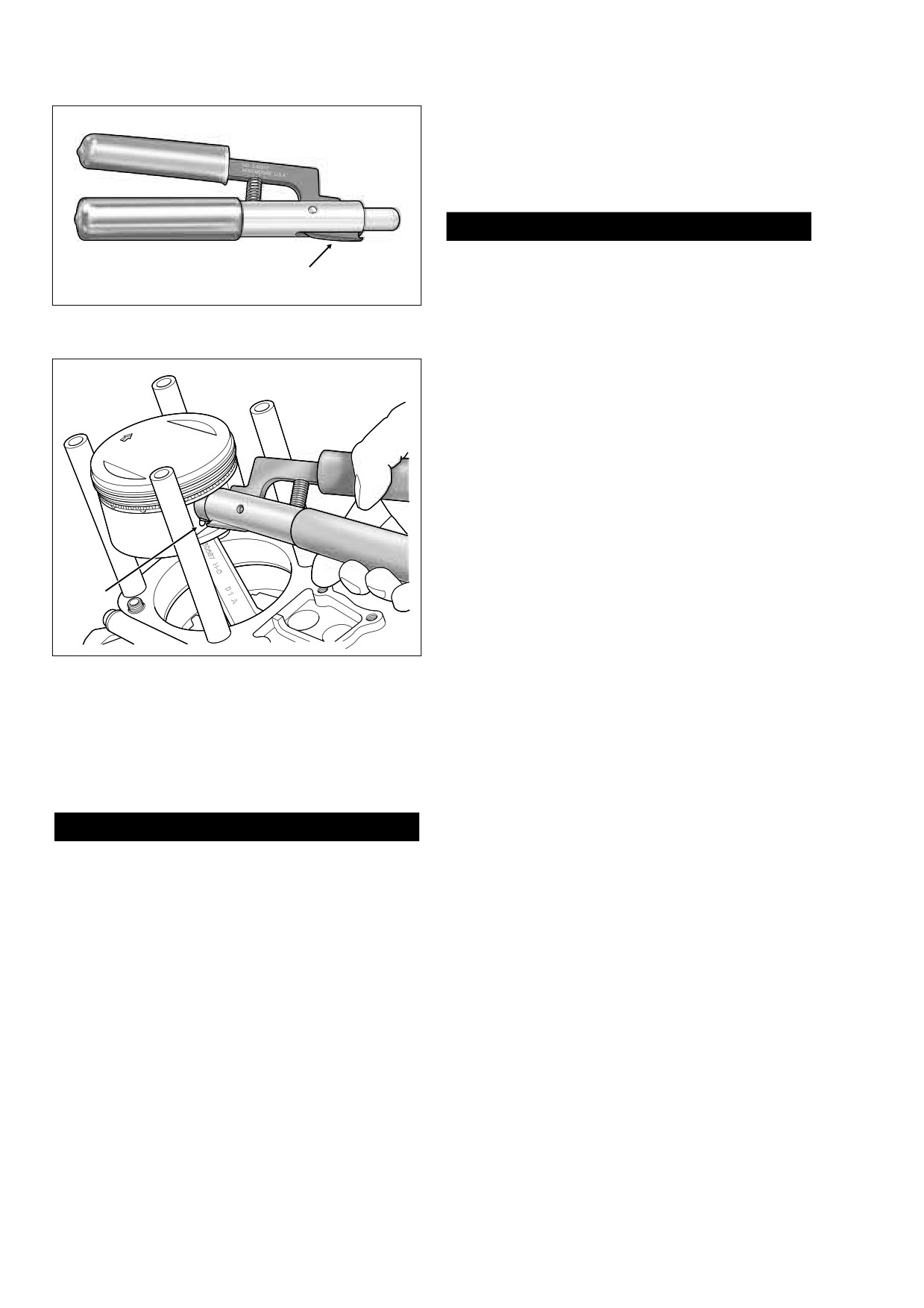
cause eye injury.
Figure 3-24. Piston Pin Circlip
25. Verify that clean shop towels are properly positioned
Remover/Installer (Part No. HD-42317A)
over the crankcase bore to prevent the piston pin circlip
from falling into the crankcase.
f1635x3x
26. Remove the piston pin circlip as follows:
a. Insert the PISTON PIN CIRCLIP REMOVER/
INSTALLER (HD-42317A) into the piston pin bore
until claw on tool is positioned in slot of piston
(directly under circlip). See Figure 3-25.
b. Squeeze the handles of the tool together and pull
from bore. In the event that the circlip should fly out,
hold a shop towel over the bore during removal.
Remove circlip from claw and discard.
NOTE
It is not necessary to remove both piston pin circlips during
Slot
piston removal. Leave the second circlip in the pin bore.
27.
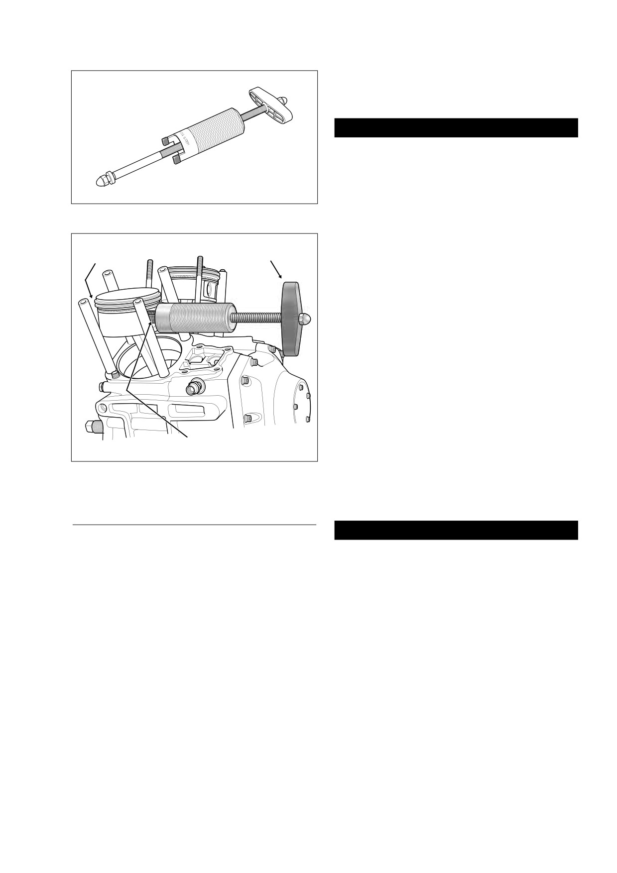
Remove the piston pin. If piston pin is difficult to remove,
use PISTON PIN REMOVER (HD-42320A). See Figure
3-26. Proceed as follows:
Figure 3-25. Remove Piston Pin Circlip
a. Remove acorn nut and spacer from rod end of tool.
b. Slide rod end through piston pin. Install spacer and
acorn nut to end of rod.
20. Raise the cylinder just enough to place clean shop tow-
els under the piston. This will prevent any dirt or debris,
c. Position rubber-coated tips of tool on flat each side
such as broken ring pieces, from falling into the crank-
of pin bore.
case bore.
d. Turn handle in a clockwise direction until piston pin
is pulled free of bore. See Figure 3-27.
CAUTION
28.
Remove the piston. Be sure to hold the rod shank
upright to prevent it from striking the crankcase. Place a
Exercise caution to avoid bending the cylinder studs.
piece of foam-type water pipe insulation around each
Even a slight bend or nick can cause a stress riser lead-
rod (about 3 inches long with a 2-1/4 inch O.D. and a 1
ing to stud failure.
inch I.D.) to prevent damage if contact should occur.
21. Carefully remove the cylinder to avoid bending the cylin-
29.
Turn the piston over and mark the pin boss with the
der studs. As the piston becomes free of the cylinder,
letters “F(ront)” or “R(ear)” to identify location. See Sec-
hold it upright to prevent it from striking the studs or
tion
3.11 SUBASSEMBLY SERVICE AND REPAIR,
dragging across the stud thread area. Mark the cylinder
PISTON and UPPER CONNECTING ROD.
“F(ront)” or “R(ear)” to identify location.
30.
If performing a top end overhaul only, see Section 3.11
SUBASSEMBLY SERVICE AND REPAIR, TOP END,
22. Slide plastic tubing, rubber hose or conduit over each
before proceeding to Section 3.9 TOP END OVERHAUL,
cylinder stud. Material approximately 6 inches (152 mm)
ASSEMBLY, which follows. If performing a complete
long with an I.D. of 1/2 inch (12.70 mm) will protect cylin-
engine overhaul, see Section
3.10 BOTTOM END
der studs and piston from damage.
OVERHAUL, DISASSEMBLY.
3-32
2006 Touring: Engine
HOME
5.
Insert piston pin through pin bore and upper connecting
rod bushing. Push pin until it contacts circlip installed in
opposite pin boss.
CAUTION
Do not reuse piston pin circlips. The circlips may weaken
during removal causing them to break or dislodge dur-
ing engine operation, a condition that will result in
engine damage.
6.
Place clean shop towels over the cylinder and lifter
Figure 3-26. Piston Pin Remover (Part No. HD-42320A)
bores to prevent the piston pin circlip from falling into the
crankcase. Verify that the circlip groove is clean and free
of dirt and grime.
Spacer and
Acorn Nut
Handle
7.
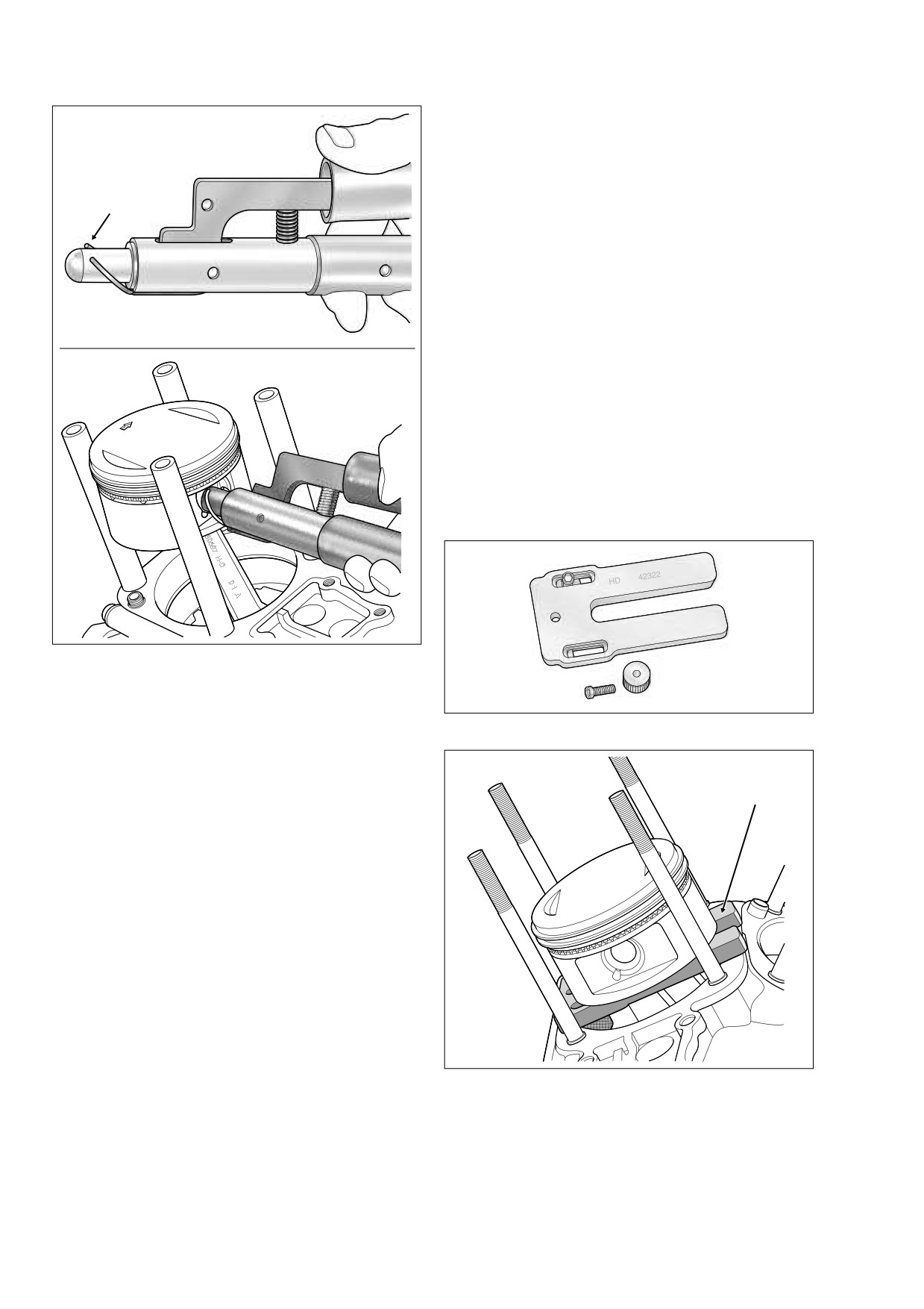
Install new piston pin circlip with the PISTON PIN CIR-
CLIP REMOVER/INSTALLER (HD-42317A). Proceed as
follows:
a. Slide circlip down nose of tool until it contacts claw.
Lightly squeeze handles of tool to capture circlip in
claw.
b. Releasing pressure on handles, rotate circlip so that
the end gap is centered at top of tool and then
recapture in claw.
c. Tilt the circlip forward until the end gap contacts
nose of tool. See upper frame of Figure 3-28.
d. Insert the tool into the piston pin bore until claw is
aligned with slot in piston.
Rubber Coated Tip
f1640x3x
e. Firmly push the tool into the piston pin bore until it
Figure 3-27. Remove Piston Pin
bottoms. Release handles and remove tool.
f.
Inspect the circlip to verify that it is fully seated in
the groove.
ASSEMBLY
CAUTION
NOTE
O-rings that are missing, distorted, pinched or otherwise
It is assumed that each step performed on one cylinder is
damaged will result in either oil leakage or low oil pres-
automatically repeated on the other.
sure. Use of the wrong O-ring will have the same results.
Since many O-rings are similar in size and appearance,
1.
Slide plastic tubing, rubber hose or conduit over each
always use new O-rings keeping them packaged until
cylinder stud, if removed. Material approximately
6
use to avoid confusion.
inches (152 mm) long with an I.D. of 1/2 inch (12.70 mm)
will protect cylinder studs and piston from damage.
8.
Install new O-ring over “downside” cylinder deck ring
dowel (that is, rear dowel on rear cylinder, front dowel on
2.
Apply clean H-D 20W50 engine oil to piston pin, piston
front cylinder). Apply a very thin film of clean H-D 20W50
bosses and upper connecting rod bushing.
engine oil to O-ring before installation. Verify that O-ring
is properly seated in groove.
3.
Remove water pipe insulation from rod shank.
4.
Place piston over rod end so that the arrow stamped at
9.
Install new O-ring seal at the bottom of the cylinder liner.
the top of the piston points toward the front of the
Apply a very thin film of clean H-D 20W50 engine oil to
engine.
O-ring before installation.
2006 Touring: Engine
3-33
HOME
b. With the forked end of the tool pointing towards the
f1564x3x
center of the engine and the adjustable knobs fac-
ing downward, capture shank of connecting rod in
fork. Lay tool on cylinder deck so that adjustable
knobs contact wall of cylinder bore.
Circlip
c. Rotate engine until piston skirt is centered and
firmly seated on top of support plate. See Figure 3-
30.
14. Install cylinder as follows:
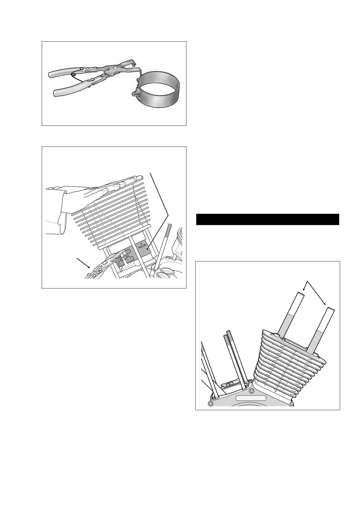
a. Obtain the PISTON RING COMPRESSOR (HD-
96333-51E).
b. Fit tabs on pliers into slots of ring compressor band
(HD-96333-103). The arrow stamped on the band
indicates the side that faces up, so disregard the
f1636x3x
word “bottom.” Place band around piston. Press the
lever on the right side of the pliers to open the jaws
for band expansion.
c. Orient tool so that the top of the band is positioned
between the top compression ring and the piston
crown. Tightly squeeze handles of tool to compress
piston rings. The racheting action of the tool allows
release of the handles after the rings are com-
pressed.
Figure 3-28. Install Piston Pin Circlip
NOTE
Figure 3-29. Piston Support Plate (Part No. HD-42322)
Excessive lubrication of cylinder sleeve O-ring seal will result
in oil weepage between cylinder and crankcase as engine is
run, a condition that may be incorrectly diagnosed as an oil
Piston
leak.
Support Plate
10. Verify that the piston ring end gaps are properly stag-
gered. If necessary, see Section 3.11 SUBASSEMBLY
SERVICE AND REPAIR, PISTON.
11. Apply clean H-D 20W50 engine oil to piston, piston rings
and cylinder bore.
12. Remove plastic tubing or rubber hose from cylinder
studs. Rotate engine until piston is at top dead center. If
necessary, see step 31 for methods of engine rotation.
13. Install the PISTON SUPPORT PLATE (HD-42322). Pro-
ceed as follows:
a. Slide both adjustable knobs on tool down slots away
f1612x3x
from forked end. Tighten knobs when contact is
made with flats at end of slots.
Figure 3-30. Install Piston Support Plate
3-34
2006 Touring: Engine
HOME
h. Carefully set the cylinder over the two ring dowels in
the cylinder deck. Push down on the cylinder until it
is fully seated in the crankcase bore.
NOTE
To hold the first cylinder in position while installing the sec-
ond, install threaded cylinders
(HD-95952-1) from CON-
NECTING ROD CLAMPING TOOL (HD-95952-33B) onto
cylinder studs with the knurled side down. This will prevent
the piston rings from raising the cylinder as the engine is
rotated to bring the other piston into position for installation of
the second cylinder. See Figure 3-33.
Figure 3-31. Piston Ring Compressor
15. With the part number topside, place the head gasket
(Part No. HD-96333-51E)
over the two ring dowels in the upper flange of the cylin-
der.
16. Note that the word “Front” or “Rear” is cast into the top of
f1613x3x
Ring Compressor Band
(3-5/8 - 3-7/8 Inches)
the cylinder head to ensure proper installation. With the
Part No. HD-96333-103
indent in the cooling fins facing the right side of the
engine (for accommodation of the push rods and cov-
ers), carefully set the cylinder head over the two cylinder
ring dowels. To avoid damage to machined surfaces or
ring dowels, lower the cylinder head at an angle that
closely approximates the angle of the crankcase.
CAUTION
Thoroughly clean and lubricate the threads of the cylin-
der head bolts before installation. Friction caused by dirt
and grime will result in a false torque indication.
Pliers
Threaded
Cylinder
Figure 3-32. Install Cylinder
d.
Note that the cylinders should have been marked
with the letters
“F(ront)” or
“R(ear)” to identify
location. With the indent in the cooling fins facing
the right side of the engine, gently slide cylinder
over the cylinder studs and the piston crown resting
it on the top of the ring compressor band.
e.
Place the palms of both hands at the top of the cyl-
inder. Push down on the cylinder with a sharp, quick
motion to pass the piston ring area. See Figure 3-
32.
f.
Rotate the engine slightly to raise piston off support
plate. Remove pliers from band and then remove
band from around shank of connecting rod. Remove
piston support plate.
f1518b3x
g.
Remove shop towels from around the crankcase
Figure 3-33. Install Threaded Cylinders to Studs
bore exercising caution to keep out any dirt or
(Part No. HD-95952-1)
debris.
2006 Touring: Engine
3-35
HOME
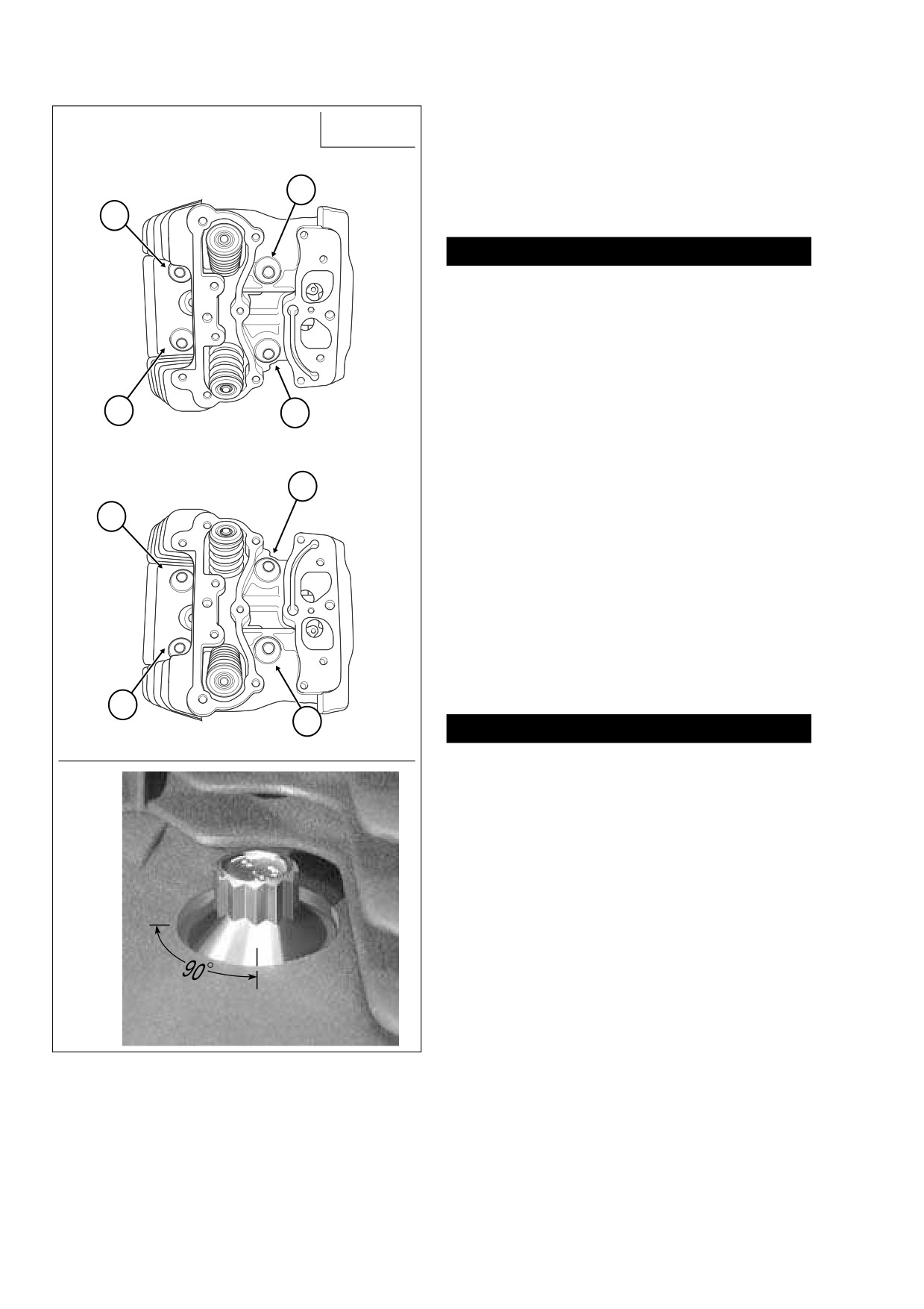
17. Lightly oil threads and shoulders of cylinder head bolts
S
= Short Bolt
with clean H-D 20W50 engine oil.
L
= Long Bolt
A
FRONT
18. Start the cylinder head bolts onto the cylinder studs, two
L
short bolts on the left side of the engine, two long bolts
4
on the right.
S
19. Tighten the four cylinder head bolts as follows:
2
CAUTION
Improperly tightened cylinder head bolts may result in
gasket leaks, stud failure and distortion of the cylinder
and/or cylinder head.
a. Alternately turn each cylinder head bolt until finger
tight.
b. Tighten the cylinder head bolts to 120-144 in-lbs
(13.6-16.3 Nm) in the sequence shown in A of Fig-
1
3
ure 3-34.
S
L
c. Following the same sequence, tighten each bolt to
L
15-17 ft-lbs (20.3-23.1 Nm).
REAR
3
d. Using a grease pencil, mark a straight line on the
S
cylinder head bolt continuing the line over onto the
1
cylinder head. Using the marks as a guide, turn
each bolt 1/4 turn or 90 degrees. See B of Figure 3-
34. Be sure to tighten the cylinder head bolts in the
sequence shown in A of Figure 3-34.
NOTE
For best results, obtain Snap-on® Torque Angle Gauge
TA360.
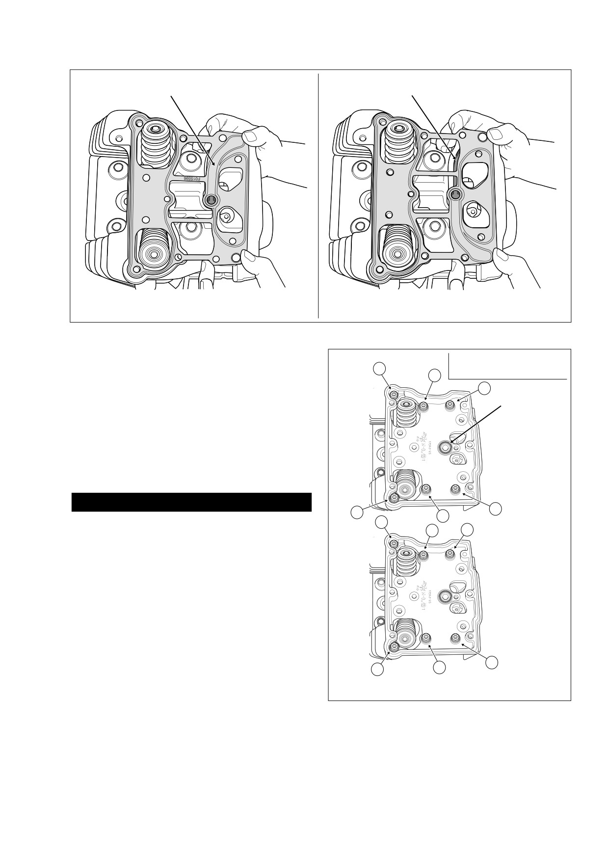
20. Install a new rocker housing gasket on the cylinder head
flange.
2
S
4
CAUTION
f2166x3x
L
Even though all bolt holes (rocker housing, rocker arm
support plate and breather assembly) may appear to be
B
in alignment, the rocker housing gasket may be installed
upside down. An upside down gasket will result in an
open breather channel causing an oil leak when the vehi-
cle is started, possibly resulting in engine and/or prop-
erty damage.
21. Verify that the rocker housing gasket is installed cor-
rectly by noting that the breather channel is concealed.
See Figure 3-35.
22. With the indent facing forward, place the rocker housing
into position aligning the holes in the housing with those
in the gasket.
23. Apply a small dab of Loctite Medium Strength Thread-
locker 243 (blue) to threads of six rocker housing bolts.
f1583x3x
Start the rocker housing bolts, two long bolts on the left
side of the engine, four intermediate bolts in the interior.
Figure 3-34. Cylinder Head Torque Sequence
Alternately tighten the bolts to 120-168 in-lbs (13.6-18.9
and Bolt Size
Nm) in the pattern shown in Figure 3-36.
3-36
2006 Touring: Engine
HOME
f1577x3x
f1576x3x
Breather Channel Concealed
Breather Channel Exposed
CORRECT
WRONG
Figure 3-35. Install Rocker Housing Gasket (Rear Cylinder Shown)
L
S
= Short Bolt, 1 In.
f2165x3x
I
= Intermediate Bolt, 1-1/4 In.
NOTE
2
I
L
= Long Bolt, 1-3/4 In.
6
If the engine was left in the chassis for service, use the
4
ROCKER HOUSING WRENCH (HD-47248) to start the
I
rocker housing bolts. With both an external and internal hex,
O-Ring
the bolts also can be installed with either a 7/16 inch socket
or open end/box wrench (open spaces), or a short 3/16 inch
allen wrench (tight spaces). For best results, final tighten the
FRONT
bolts on the left side of the engine (where there is close prox-
imity to the frame) to 120-168 in-lbs using a torque wrench
with a 1/4 inch drive.
CAUTION
I
1
3
5
I
O-rings that are missing, distorted, pinched or otherwise
L
3
Torque: 120-168 in-lbs
L
5
1
damaged will result in either oil leakage or low oil pres-
I
I
sure. Use of the wrong O-ring will have the same results.
Since many O-rings are similar in size and appearance,
always use new O-rings keeping them packaged until
use to avoid confusion.
24. Install new O-ring in groove around breather baffle hole
in rocker housing. Apply a thin film of clean H-D 20W50
REAR
engine oil to O-ring before installation. See Figure 3-36.
25. Install the hydraulic lifters in the crankcase bores with
the flats facing forward and rearward. To preserve exist-
ing wear patterns, orientation of the oil hole (inboard or
4
2
6
I
outboard) should have been noted during disassembly.
L
I
To avoid damage, do not drop lifters onto cam lobes.
Install Six Rocker Housing Bolts.
26. Place anti-rotation pin on the machined flat between the
Figure 3-36. Rocker Housing Torque Sequence
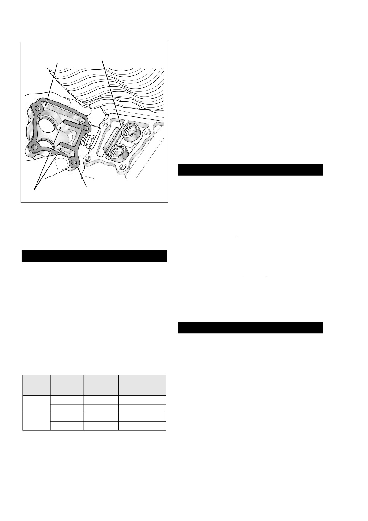
blocks cast into the crankcase. See Figure 3-37.
and Bolt Size
2006 Touring: Engine
3-37
HOME
Do not install the spring cap retainers at this time. To
Anti-Rotation
ensure proper installation, take note of Table 3-3.
Pin
Lifter Cover
30. Install the push rods in their original positions. Be sure to
remove any tags that may have been used for marking
location and orientation. To ensure proper installation,
take note of Table 3-3. For example, if reassembling the
rear cylinder, slide the intake push rod (silver) through
the front hole in the rocker housing engaging the lifter
socket in the inside hole of the lifter cover. Slide the
exhaust push rod (black) through the rear hole in the
rocker housing engaging the lifter socket in the outside
hole of the lifter cover.
31. To install the rocker arm support plate, both lifters of the
cylinder being serviced must be on the base circle (or
lowest position) of the cam.
CAUTION
Installing the rocker arms and rotating the engine with
the valve train loaded can result in bent push rods and/
Gasket
Ribs
f1606x3x
or valve damage.
Figure 3-37. Install Lifters and Lock Position
To find the base circle, it is first necessary to rotate the
With Anti-Rotation Pin
engine. Based on the level of disassembly, three meth-
ods of engine rotation are presented below.
27. Install a new lifter cover gasket aligning the holes in the
a. With primary cover installed - With vehicle on center
gasket with those in the cover.
stand, place the transmission in 5th gear and rotate
rear wheel in a clockwise direction (as viewed from
CAUTION
right side) until the base circle is found. See step
31(d) to find the base circle.
Movement or loss of the anti-rotation pin can result in
lifter rotation causing catastrophic engine damage.
b. With primary cover removed
- Remove primary
cover. Place the transmission in neutral. Fit a 1-1/2
28. Install the lifter cover and start the four allen head socket
inch socket on the compensating sprocket shaft nut.
screws (1/4 x 1 inch). During installation, verify that the
Rotate nut in a counterclockwise direction until the
anti-rotation pin is held in place by the ribs cast into the
base circle is found. See step 31(d) to find the base
inboard side of the lifter cover. See Figure 3-37. Tighten
circle.
the lifter cover screws to 90-120 in-lbs (10.2-13.6 Nm) in
a crosswise pattern.
CAUTION
29. Hand compress the push rod cover assembly and fit the
O-ring end of the lower push rod cover into the lifter
Do not attempt to rotate engine by removing cam cover
cover bore. Expanding the assembly, fit the O-ring end of
and placing socket on crank or primary cam sprocket
the upper push rod cover into the cylinder head bore.
flange bolt. Head of flange bolt can break off possibly
resulting in damage to flywheel or camshaft.
Table 3-3. Push Rod/Cover Locations
c. With engine mounted in engine stand - Obtain the
Cylinder Head/
Cover and
Lifter Cover
ENGINE ROTATION WRENCH (HD-47257). See
Cylinder
Rocker Housing
Push Rod*
Bore
Figure 3-23. Install tool on sprocket shaft and rotate
Bore
in a counterclockwise direction until the base circle
Intake
Inside
Rear
is found. See step 31(d) to find the base circle.
Front
Exhaust
Outside
Front
d. Finding the base circle: Using one of the methods
Intake
Inside
Front
Rear
above, rotate engine until piston is at Top Dead
Exhaust
Outside
Rear
Center (TDC) of compression stroke. To accomplish
* Push Rods Are Color Coded - Intake (Silver), Exhaust (Black)
3-38
2006 Touring: Engine
HOME
S
= Short Bolt, 1 In.
f2163x3x
f2164x3x
I
= Intermediate Bolt, 1-1/4 In.
Rocker Arm Torque:
L
= Long Bolt, 1-3/4 In.
18-22 ft-lbs
3
5
4
1
S
L
Breather
Assembly
Torque: 15-18 ft-lbs
Torque: 90-120 in-lbs
2
1
L
S
FRONT
2
6
4
3
L
S
6
L
2
3
4
S
2
1
L
S
REAR
3
1
4
L
5
S
A
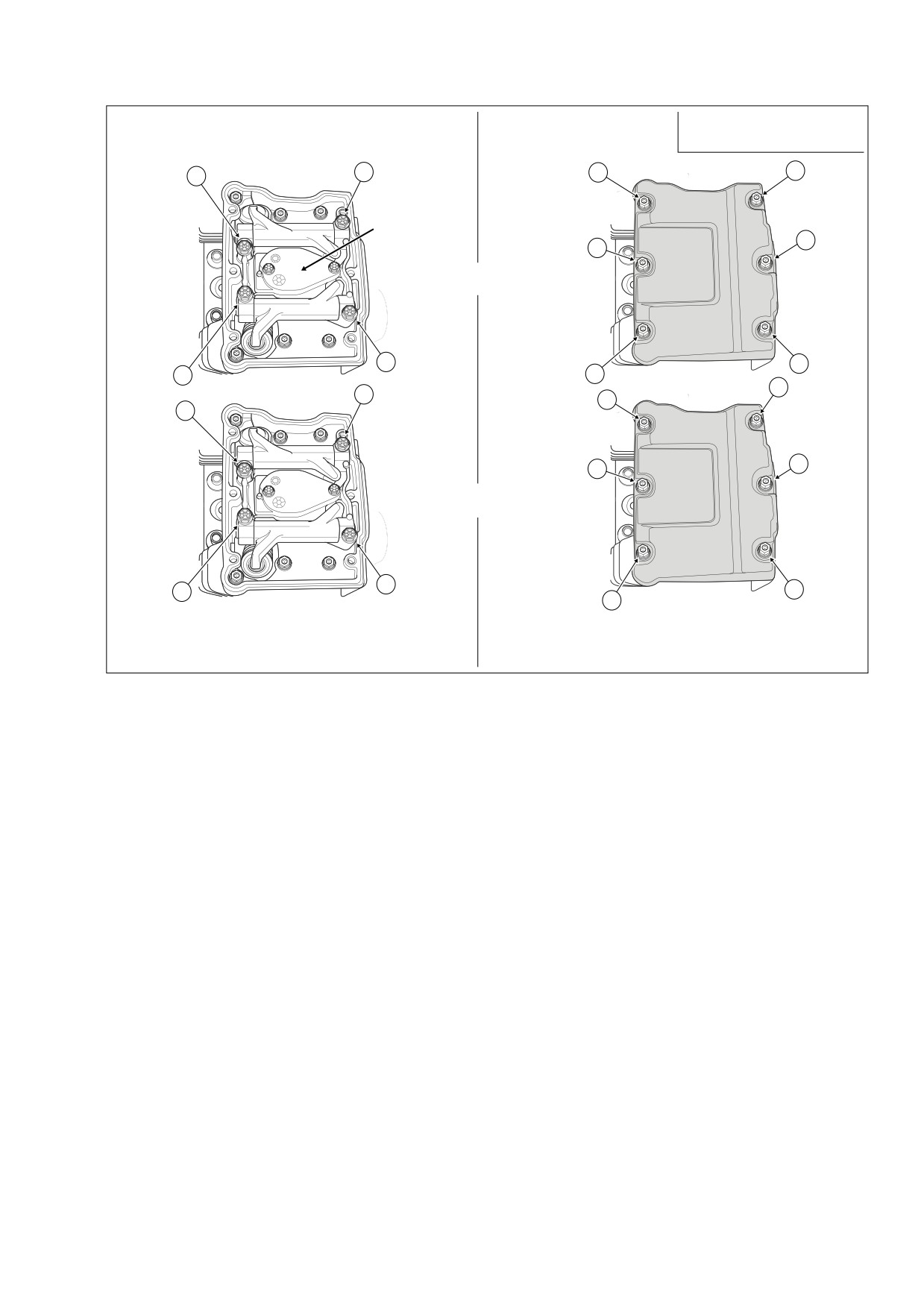
Alternately Tighten Four Rocker Arm Bolts
B
Install Six Rocker Cover Bolts.
1/4 Turn in Pattern Shown.
Figure 3-38. Rocker Arm/Rocker Cover Torque Sequence and Bolt Size
this, first raise lower push rod cover to access intake
34. Alternately tighten each of the four rocker arm support
lifter (inside hole of lifter cover). Place index finger
plate bolts just 1/4 turn following the pattern shown in A
on top of the intake lifter. While rotating engine, feel
of Figure
3-38. Continue turning the bolts in these
lifter rise (valve open) and fall (valve closed). Now
increments until snug. Following the same numerical
place finger tightly over spark plug hole and rotate
sequence, tighten the bolts to 18-22 ft-lbs (24.4-29.8
engine again. In the compression stroke, air will be
Nm).
forced out against your finger until the piston
35. Alternately tighten the two breather assembly bolts to
reaches the TDC position. Stop engine rotation
90-120 in-lbs (10.2-13.6 Nm).
when the flow of air through the spark plug hole
stops. Direct the beam of a small flashlight into
NOTE
spark plug hole to verify piston is at TDC. Both
If the engine was left in the chassis for service, final tighten
intake and exhaust valves are now closed and the
the rocker arm support plate bolt on the rear left side of the
push rods are in the unloaded position.
rear cylinder using a 3/8 inch drive torque wrench with a 1/2
inch flank drive
“dog bone” torque adapter
(Snap-On
32.
Place the rocker arm support plate assembly into the
FRDH161). Since any extension can act as a torque multi-
rocker housing. Start the four rocker arm support plate
plier, the torque wrench must be perpendicular to the torque
bolts into the cylinder head.
adapter when the bolt is tightened. The 90 degree orientation
33.
Place breather assembly at top of rocker arm support
between the tools cancels the multiplier effect and prevents
plate. Apply a small dab of Loctite Medium Strength
the bolt from being over-tightened. If the adapter is kept inline
Threadlocker
243 (blue) to threads of two breather
with the torque wrench, the multiplier effect is in force and
assembly bolts. Start bolts into cylinder head.
distortion of the rocker housing will occur.
2006 Touring: Engine
3-39
HOME
39. Apply a small dab of Loctite Medium Strength Thread-
locker 243 (blue) to threads of six rocker cover bolts.
Start the rocker cover bolts, three short bolts on the left
side of the engine, three long bolts on the right. Tighten
the bolts to 15-18 ft-lbs (20.3-24.4 Nm) in the pattern
shown in B of Figure 3-38.
NOTE
If the engine was left in the chassis for service, final tighten
the three rocker cover bolts on the left side of the rear cylin-
der using a 3/8 inch drive torque wrench with a 7/16 inch
flank drive “dog bone” torque adapter (Snap-On FRDH141).
Since any extension can act as a torque multiplier, the torque
wrench must be perpendicular to the torque adapter when
the bolts are tightened. The 90 degree orientation between
the tools cancels the multiplier effect and prevents the bolts
from being over-tightened. If the adapter is kept inline with
the torque wrench, the multiplier effect is in force and distor-
tion of the rocker cover will occur.
f1604x3x
40.
If engine was left in the chassis for service, see Section
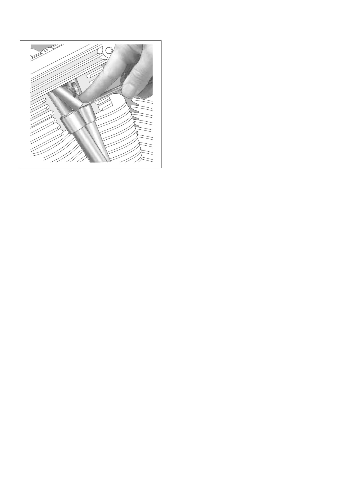
Figure 3-39. Install Spring Cap Retainer
3.6 ASSEMBLING MOTORCYCLE AFTER STRIPPING.
If engine was removed for service,
see
Section
3.8
INSTALLING ENGINE IN CHASSIS.
36. Lift up lower push rod covers and verify that both push
rods spin freely.
NOTE
Always service each cylinder separately. After the first cylin-
der is serviced the engine must be rotated to find the base
circle on the second cam. Service on the remaining cylinder
can then proceed.
37. Complete installation of the push rod covers as follows:
a. Verify that the O-ring ends of the upper and lower
push rod covers fit snugly into the cylinder head and
lifter cover bores.
b. Lodge the upper edge of spring cap retainer into the
cylinder head bore leaving the bottom edge free.
c. Insert blade of small screwdriver between bottom
edge of spring cap retainer and top of spring cap.
d. While simultaneously depressing spring cap with tip
of screwdriver, use forefinger to slide bottom edge
of spring cap retainer down shaft towards tip of
screwdriver blade. As spring cap reaches its full
length of travel, spring cap retainer should be in
approximate position against upper push rod cover.
See Figure 3-39.
NOTE
For best results, be sure that screwdriver, spring cap and
spring cap retainer are free of grease and oil.
e. Verify that spring cap retainer is seated tightly
against upper push rod cover.
38. Install a new rocker cover gasket on the rocker housing
flange. Place the rocker cover into position aligning the
holes in the cover with those in the gasket.
3-40
2006 Touring: Engine
HOME
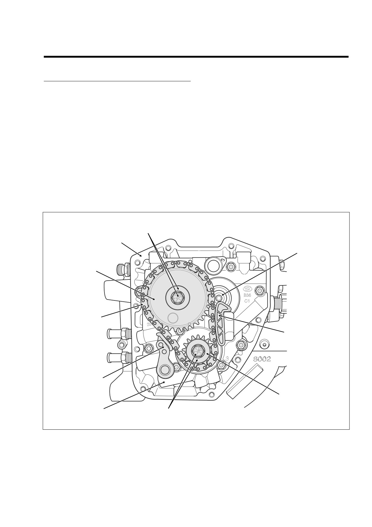
BOTTOM END OVERHAUL
3.10
3.
Using a colored marker, mark the crank sprocket and
DISASSEMBLY
one of the links of the primary cam chain. Maintaining
the original direction of rotation during assembly may
1.
See Section 3.9 TOP END OVERHAUL, DISASSEM-
prolong service life.
BLY. If only servicing cam compartment components,
4.
Remove the flange bolt and flat washer from the crank
see steps 1-11. If performing a complete engine over-
sprocket. See Figure 3-40.
haul, reference steps 1-29.
5.
Remove the flange bolt and flat washer from the primary
cam sprocket.
NOTE
NOTE
The cam support plate and lifter cover use the same short
If too much loctite, or perhaps the wrong loctite, was used to
allen head socket screw (1/4 x 1 inch). Only the cam cover
install the primary cam sprocket flange bolt, it may be very
uses the longer screw (1/4 x 1-1/4 inches). For ease of
difficult to remove. In these cases, break down loctite using
assembly, do not mix short and long screws. Store long
heat from a small propane torch. Apply flame evenly around
screws inside cam cover to avoid confusion. The short
bolt head in a circular motion, but not for so long as to turn
screws are interchangeable.
bolt blue. Do not direct heat at chain tensioner assembly and
other components or damage will result. Other methods of
2.
Remove the ten allen head socket screws to release the
removal, such as use of a large breaker bar, also may result
cam cover. Remove and discard the cam cover gasket.
in damage to chain drive and other components.
Flange Bolt and
Flat Washer
Right
Crankcase Half
Front
Camshaft
Primary Cam
Sprocket
Primary
Cam Chain
Chain Guide
Primary Cam Chain
Tensioner
Crank
Sprocket
Oil Pressure
Flange Bolt and
f2141b3x
Relief Valve
Flat Washer
Figure 3-40. Cam Support Plate Assembly
2006 Touring: Engine
3-41
HOME
7.
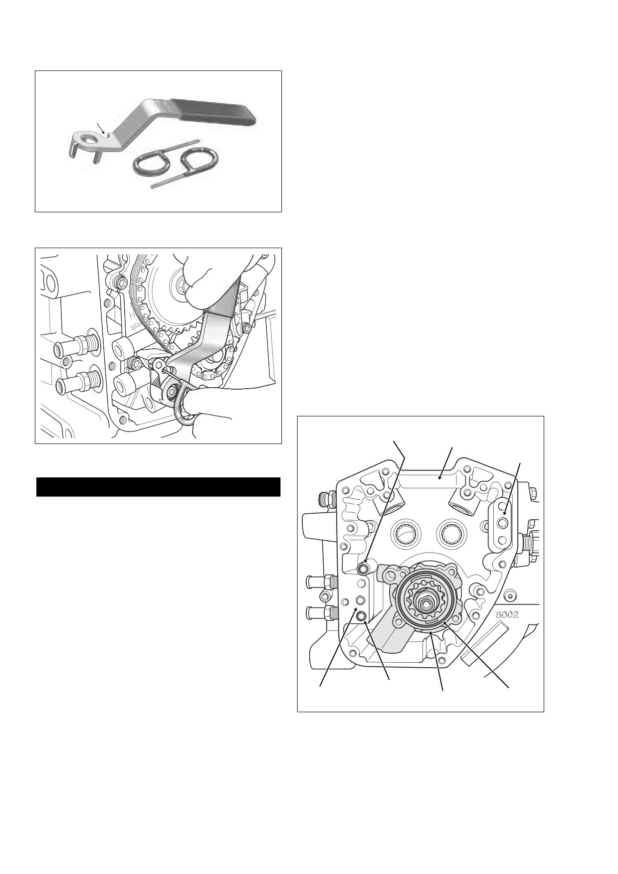
Insert small pry bar (seal remover) between inboard side
of primary cam sprocket and cam support plate. Working
Tensioner
around its circumference, carefully ease primary cam
Unloader
sprocket off splines of rear camshaft until loose.
Slot
8.
Ease off crank sprocket with a slightly smaller pry bar
(seal remover). Remove the primary cam sprocket, pri-
mary cam chain and crank sprocket.
9.
Remove the primary cam sprocket spacer from the rear
camshaft.
Retention Pins
10.
Squeeze tabs to remove chain guide from between
blocks cast into cam support plate.
11.
Release the cam support plate from the oil pump flange.
Figure 3-41. Cam Chain Tensioner Unloader
Alternately loosen and then remove the four allen head
with Retention Pins (Part No. HD-42313)
socket screws following the pattern shown in B of Figure
3-50.
12.
Release the cam support plate from the crankcase
flange. Alternately loosen and then remove the six allen
head socket screws following the pattern shown in A of
Figure 3-50.
13.
Two ring dowels in crankcase flange locate cam support
plate (lower rear, upper front). See Figure 3-43. Insert
small pry bar (seal remover) between inboard side of
cam support plate and crankcase flange in area adja-
cent to ring dowels. Alternately work each side free and
then carefully ease cam support plate from end of crank-
shaft. See Section 3.11 SUBASSEMBLY SERVICE AND
REPAIR, CAM SUPPORT PLATE.
f1573b3x
O-Ring
f2140x3x
Right
Blind Hole
Crankcase Half
Ring
Figure 3-42. Retract Primary Cam Chain Tensioner
Dowel
1WARNING
Use extreme caution when operating propane torch.
Read the manufacturers instructions carefully before
use. Do not direct open flame or heat toward any fuel
system component. Extreme heat can cause fuel ignition
and explosion. Inadequate safety precautions could
result in death or serious injury.
6.
Using the CAM CHAIN TENSIONER UNLOADER (HD-
42313), retract the primary cam chain tensioner as fol-
lows:
a. With the handle pointing toward the front of the cam
support plate, place cup of tool over spring coil. Cor-
rectly positioned, the slot in the tool should be adja-
cent to the hole in the tensioner. See Figure 3-42.
b. Rotate the handle of the tool in a counterclockwise
direction until the hole in the tensioner is aligned
O-Ring
with the hole in the boss of the cam support plate.
Ring
Oil Feed Hole
O-Ring
Dowel
Oil Pump
c. Insert a retention pin through the hole in the ten-
sioner and into the hole in the cam support plate.
Figure 3-43. Oil Pump Assembly
3-42
2006 Touring: Engine
HOME
1CAUTION
Do not pull the retention pin from the primary cam chain
tensioner after removal of the cam support plate. With
35-40 pounds of spring pressure behind the tensioner,
allowing it to accelerate through its full length of travel
will result in spring stretching and/or cracking of the ten-
sioner shoe. Furthermore, if the tensioner should con-
tact fingers or other parts of the hand, minor or
moderate injury may occur.
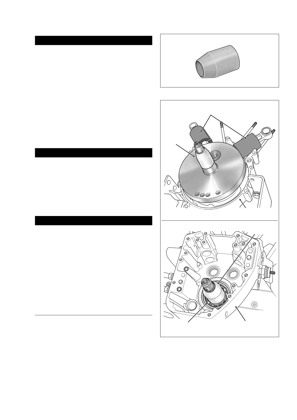
Figure 3-44. Crankshaft Guide (Part No. HD-42326A)
14. Remove O-ring from groove around oil feed hole in
crankcase flange
(directly below rear ring dowel).
Remove O-ring from groove around blind hole in boss
Water Pipe
f1644x3x
(directly above oil return hole in crankcase flange). Dis-
Insulation
card O-rings. See Figure 3-43.
15. Pull oil pump from crankshaft. Remove O-ring from out-
board side of oil pump housing. Remove O-ring from
scavenge port stub. Discard O-rings. See Section 3.11
Crankshaft
SUBASSEMBLY SERVICE AND REPAIR, OIL PUMP.
Guide
1WARNING
Be sure that stator mount flange (sprocket shaft side) is
NOT facing up when the case halves are separated or the
flywheel assembly will drop to the floor. Dropping the fly-
wheel assembly may result in parts damage and minor
or moderate injury.
16. Rotate crankcase in the engine stand so that the cam
cover flange is facing upward. Remove the nine crank-
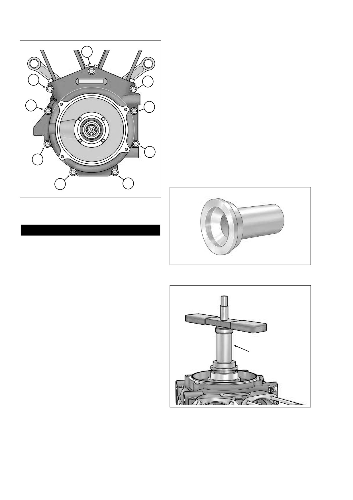
case bolts in the left case half. Follow the sequence
shown in Figure 3-46.
Left
Crankcase Half
1CAUTION
f1645a3x
Crankshaft
Never move or lift the crankcase by grasping the cylin-
Guide
der studs. The crankcase is too heavy to be carried in
this manner and may be dropped. Dropping the crank-
case may result in parts damage and minor or moderate
injury.
17. Using pry points, loosen case halves. Lift right crank-
case half off end of crankshaft.
18. Remove O-rings from two ring dowels in split line face of
right case half. Discard the O-rings.
19. See Section
3.11 SUBASSEMBLY SERVICE AND
REPAIR, CRANKCASE.
ASSEMBLY
1.
If removed, install left crankcase half in engine stand so
Crankshaft
Right
that the split line face is vertical.
Bearing
Crankcase Half
2.
To prevent damage to the sprocket shaft bearing, slide
CRANKSHAFT GUIDE
(HD-42326A) over end of
Figure 3-45. Install Crankshaft Guide to Protect
sprocket shaft. Install flywheel assembly into left case
Crankshaft Bearing
half. Remove tool.
2006 Touring: Engine
3-43
HOME
7.
Rotate crankcase in the engine stand so that the stator
mount flange (sprocket shaft side) is facing upward.
1
Install service thrust washer on sprocket shaft with the
ink stamp facing out (and the chamfer inboard). If using
OE part without markings, orient as required to preserve
existing wear pattern.
5
4
8.
To install new oil seal into bearing bore, obtain pilot,
Nice bearing, large flat washer and handle from
SPROCKET SHAFT TIMKEN BEARING CONE
INSTALLER (HD-97225-55B) and proceed as follows:
7
8
a. Verify that seal lip garter spring is in place on both
sides of seal.
b. Thread pilot onto sprocket shaft until contact is
made with shoulder.
c. With the lettering facing outside, slide oil seal over
pilot until it contacts bearing bore.
2
3
d. Slide SPROCKET SHAFT OIL SEAL INSTALLER
(HD-39361A) over pilot until it contacts oil seal. See
Figure 3-47.
9
6
f1585x3x
Figure 3-46. Crankcase Torque Sequence
(Left Side View)
CAUTION
O-rings that are missing, distorted, pinched or otherwise
damaged will result in either oil leakage or low oil pres-
sure. Use of the wrong O-ring will have the same results.
Since many O-rings are similar in size and appearance,
always use new O-rings keeping them packaged until
Figure 3-47. Sprocket Shaft Oil Seal Installer
use to avoid confusion.
(Part No. HD-39361A)
3.
Install new O-rings over two ring dowels in split line face
of right case half.
4.
Apply a small bead of sealant approximately 0.056 inch
f1882x3x
(1.4 mm) wide to the split line face. For best results, use
High-Performance Sealant (gray), Part No. HD-99650-
02.
5.
To prevent damage to the crankshaft bearing, place
CRANKSHAFT GUIDE (HD-42326A) over end of crank-
shaft. Mate case halves sliding bearing in right crank-
case half over end of crankshaft. Remove tool. See
Figure 3-45.
Sprocket Shaft
Oil Seal Installer
6.
Start the nine crankcase bolts and tighten as follows:
a. Alternately turn each crankcase bolt until finger
tight.
b. Tighten the crankcase bolts to 10 ft-lbs (13.6 Nm) in
the sequence shown in Figure 3-46.
c. Following the same sequence, tighten each bolt to
15-19 ft-lbs (20.3-25.8 Nm).
Figure 3-48. Install Oil Seal In Bore
3-44
2006 Touring: Engine
HOME
e. Slide Nice bearing and large flat washer over pilot
until contact is made with seal installer.
Rear
Front
Camshaft
Camshaft
f.
Thread handle onto pilot shaft.
g. Rotate handle in a clockwise direction until oil seal
installer makes firm contact with crankcase stator
mount. See Figure 3-48.
h. Remove handle, flat washer, Nice bearing, seal
installer and pilot from sprocket shaft.
9.
Slide sprocket shaft spacer over end of sprocket shaft.
Push spacer into oil seal until seated against bearing
race.
10. Rotate crankcase in the engine stand so that the cam
cover flange is facing upward.
11. Install oil pump as follows:
Pin Stamped
f2068b3x
Timing Lines
CAUTION
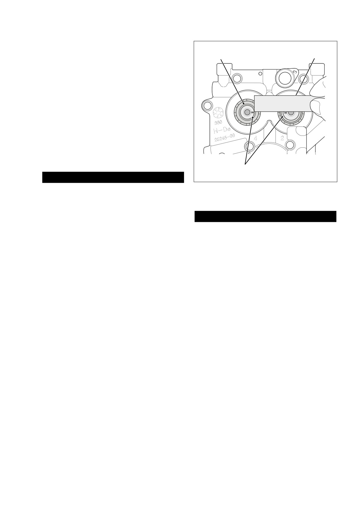
Figure 3-49. Verify Alignment of Timing Lines
O-rings that are missing, distorted, pinched or otherwise
on Front and Rear Camshafts
damaged will result in either oil leakage or low oil pres-
sure. Use of the wrong O-ring will have the same results.
Since many O-rings are similar in size and appearance,
always use new O-rings keeping them packaged until
CAUTION
use to avoid confusion.
O-rings that are missing, distorted, pinched or otherwise
a. Install new O-ring on scavenge port stub of oil
damaged will result in either oil leakage or low oil pres-
pump housing. Apply a very thin film of clean H-D
sure. Use of the wrong O-ring will have the same results.
20W50 engine oil to O-ring before installation.
Since many O-rings are similar in size and appearance,
always use new O-rings keeping them packaged until
b. Slide oil pump housing onto crankshaft fitting O-ring
use to avoid confusion.
on scavenge port stub into crankcase bore at back
of cam compartment. Firmly push on scavenge port
g. Install new O-ring in groove on outboard side of oil
stub with thumb to be sure that it is snug in bore.
pump housing. See Figure 3-43. Apply a very thin
Inspect O-ring on stub to verify that it is not pinched
film of clean H-D 20W50 engine oil to O-ring before
or distorted.
installation.
c. Separate the gerotor gears into two sets, one wide
12. Install new O-ring in groove around oil feed hole in
(scavenge) and the other narrow (feed).
crankcase flange (directly below rear ring dowel). Install
new O-ring around blind hole in boss (directly above oil
NOTE
return hole in crankcase flange). Apply a thin film of H-D
Lubricate parts with clean H-D 20W50 engine oil during
20W50 engine oil to O-rings before installation.
assembly.
13. If not retracted, place cup of CAM CHAIN TENSIONER
UNLOADER (HD-42313) over spring coil of secondary
d. Fit the smaller of the wide gerotor gears into the
cam chain tensioner positioning finger on tool between
larger. Slide the wide gerotor set down the crank-
tensioner and shoe. Rotate tool in a counterclockwise
shaft until it bottoms in the oil pump housing.
direction inserting retention pin through hole in boss on
e. Slide the first of two separator plates down the
primary cam chain side of cam support plate. Pin
crankshaft until it contacts the wide gerotor set.
engages hooks on tensioner to hold it in the retracted
Install wave washer and second separator plate.
position. For best results, place cam support plate in a
vise using brass jaw inserts to prevent casting damage.
f.
Fit the smaller of the narrow gerotor gears into the
larger. Slide the narrow gerotor set down the crank-
14. Lubricate cam needle bearings with clean H-D 20W50
shaft until it contacts the separator plate.
engine oil.
2006 Touring: Engine
3-45
HOME
6
3
2
5
2
4
4
1
1
3
A
CAM SUPPORT PLATE
B
OIL PUMP
f1581c3x
f1581c3x
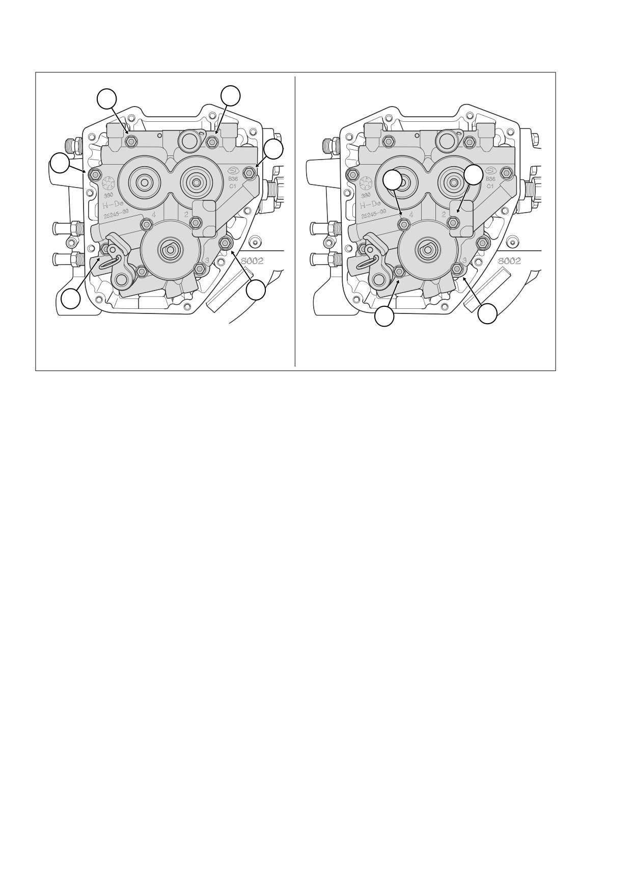
Figure 3-50. Cam Support Plate/Oil Pump Torque Sequence
15.
Using a straightedge, verify that the pin stamped timing
d. Alternately snug and then tighten the screws in
lines on the ends of the front and rear camshafts are in
holes 3 and 4 to 40-45 in-lbs (4.5-5.1 Nm).
alignment (although they may be somewhat difficult to
e. Remove the alignment tool from hole 1. Install the
see). See Figure 3-49. If necessary, rotate camshafts in
allen head socket screw and tighten to 40-45 in-lbs
order to make this observation.
(4.5-5.1 Nm).
16.
Aligning bushing in cam support plate with end of crank-
f.
Repeat step 18(e) to replace alignment tool in hole
shaft, slide cam support plate over crankshaft onto two
2 with allen head socket screw.
ring dowels in crankcase flange. Use a rubber mallet to
fully seat cam support plate on ring dowels.
g. Final tighten all four screws to 90-120 in-lbs (10.2-
13.6 Nm). Use the pattern shown in B of Figure 3-
17.
Install the six allen head socket screws (1/4 x 1 inch) to
50. Numbers cast adjacent to the bolt holes also
secure the cam support plate to the crankcase flange.
indicate the oil pump torque sequence.
Tighten screws to 90-120 in-lbs (10.2-13.6 Nm) in the
pattern shown in A of Figure 3-50.
NOTE
18.
Secure the cam support plate to the oil pump flange as
If only realigning the oil pump, first loosen all screws following
follows:
the pattern shown in B of Figure 3-50. Remove screws from
holes 1 and 2 and then follow the alignment procedure start-
a. Start two allen head socket screws (1/4 x 1 inch)
ing at step 18(b).
into holes 3 and 4. See B of Figure 3-50.
b. Obtain two ALIGNMENT TOOLS used to install lifter
19. Pull retention pin from hole in cam support plate to
guides on Evolution engines (HD-33443). Loosely
release secondary cam chain tensioner.
install alignment tools in holes 1 and 2.
20. Squeeze tabs and install chain guide between blocks
c. While rotating the engine, alternately snug and then
cast into cam support plate.
tighten the alignment tools to 40-45 in-lbs (4.5-5.1
21. Install primary cam sprocket spacer onto rear camshaft.
Nm).
22. If using the original cam support plate, camshafts, pri-
NOTE
mary cam sprocket, crank sprocket and flywheel assem-
For methods of engine rotation, see Section 3.9 TOP END
bly, then move to step 23. However, if any of these parts
OVERHAUL, DISASSEMBLY, step 6.
have been replaced, then proceed as follows:
3-46
2006 Touring: Engine