Harley Davidson FLHRC 2006. Maintenance & Repair Manual - page 12
HOME
a. With the vehicle resting on the jiffy stand on level
ground, wipe off the dipstick and insert it back into
CAUTION
the oil pan with the plug pushed completely into the
fill spout.
Check the engine oil level if the oil pressure indicator
lamp remains illuminated. If the oil level is normal, stop
b. Remove the dipstick and note the level of the oil. Oil
the engine immediately. Do not ride the vehicle until the
level should register between the two arrows on the
probem is located and corrected.
dipstick. See Figure 3-1. If oil level is at or below the
lower arrow, add only enough oil to bring the level
If the indicator lamp is not extinguished, it may be the result
between the two arrows on the dipstick.
of a low oil level or diluted oil supply. In freezing weather, the
oil feed and return lines can clog with ice or sludge. A defect
11. Perform engine oil level HOT CHECK as follows:
in the lamp wiring, faulty oil pressure switch/sender, dam-
aged oil pump, plugged oil filter element, incorrect oil viscos-
a. Ride vehicle until engine is at normal operating tem-
ity, broken or weak spring in the oil pressure relief valve and/
perature.
or damaged or incorrectly installed O-rings in the engine may
b. With the vehicle resting on the jiffy stand on level
also cause the indicator lamp to remain on.
ground, allow engine to idle for 1-2 minutes. Turn
To troubleshoot the problem, always check the engine oil
engine off.
level first. If the oil level is OK, determine if oil returns to the
c. Wipe off the dipstick and insert it back into the oil
pan from the oil return hose. If oil does not return, shut off the
pan with the plug pushed completely into the fill
engine until the problem is located and corrected.
spout.
To check the engine oil pressure, proceed as follows:
d. Remove the dipstick and note the level of the oil.
Add only enough oil to bring the level to the FULL
1.
Verify engine oil level. See CHECKING ENGINE OIL
mark on the dipstick. See Figure 3-1. Do not overfill.
LEVEL in this section.
12. Start engine and carefully check for oil leaks around
2.
Locate the oil pressure switch/sender at the front right
drain plug and oil filter.
side of the crankcase.
3.
On FLHR/C/S models, pull elbow from post of oil pres-
sure switch. On FLHX, FLHT/C/U and FLTR models, pull
WINTER LUBRICATION
external latch outward and use rocking motion to remove
Delphi connector from oil pressure sender.
Combustion in an engine produces water vapor. During start-
ing and warm-up in cold weather, especially in freezing tem-
4.
On FLHR/C/S models, use a 15/16 inch Open End Crow
peratures, the vapor condenses to water before the
Foot (Snap-On FC30B) to remove oil pressure switch
from crankcase. On FLHX, FLHT/C/U and FLTR models,
crankcase is hot enough to exhaust it through the breather
system. If the engine is run long enough for the crankcase to
use 1-1/16 inch Open End Crow Foot (Snap-On FC34A)
become thoroughly heated, the water returns to vapor and is
to remove oil pressure sender.
then exhausted.
5.
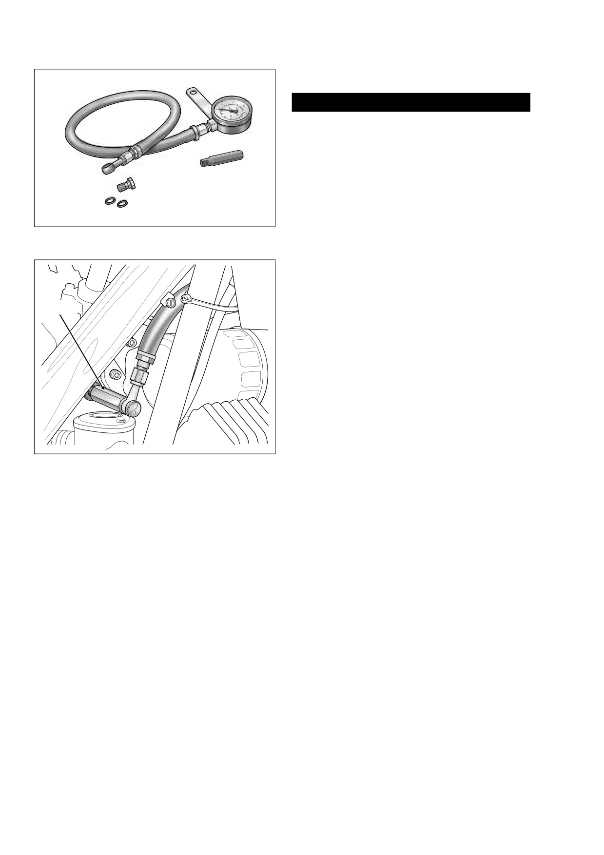
Start OIL PRESSURE GAUGE ADAPTER (HD-96921-
110) into crankcase bore. Using a 5/8 inch open end/box
An engine used for only short trips, and seldom allowed to
wrench, turn adapter until snug. See Figure 3-4.
thoroughly warm up, accumulates increasing amounts of
water in the oil pan. Water mixed with oil forms a sludge that
6.
Moving to left side of vehicle, route banjo fitting and hose
causes accelerated engine wear. In freezing temperatures,
of OIL PRESSURE GAUGE
(HD-96921-52B) over
the water becomes slush or ice, which may clog oil lines and
shifter lever and oil filter to right side of engine. See Fig-
result in engine failure.
ure 3-5.
7.
Slide washer on banjo bolt and insert through banjo fit-
Always change the engine oil more often in winter. If the
engine is used for short runs, change the oil even more fre-
ting on gauge. Install second washer on bolt and thread
quently. The farther below freezing the temperature drops the
into adapter until snug.
more often the oil should be changed.
8.
Run vehicle or simulate road running until engine is at
normal operating temperature, approximately
230o F.
(110o C.). Gauge reading will not be accurate if engine is
OIL PRESSURE INDICATOR LAMP
not completely warmed.
9.
Verify that oil pressure is 30-38 psi (207-262 kN/m2) at
The red OIL PRESSURE indicator lamp illuminates to indi-
2000 rpm.
cate improper circulation of the engine oil. The lamp illumi-
nates when the ignition is first turned on (before the engine is
10.
Remove banjo bolt (and washers) from adapter. Remove
started), but should be extinguished once the engine is run-
gauge from vehicle and then remove adapter from
ning.
crankcase.
2006 Touring: Engine
3-7
HOME
ENGINE OIL FLOW
Gauge
CAUTION
The oiling system is carefully designed for optimum effi-
ciency. All oil holes and passageways are specially
sized. Exercise caution to avoid enlarging oil holes dur-
ing cleaning. Any modification of the oiling system will
adversely affect oil pressure or cooling and lubrication
Banjo
Adapter
efficiency.
Bolt
Part No. HD-96921-110
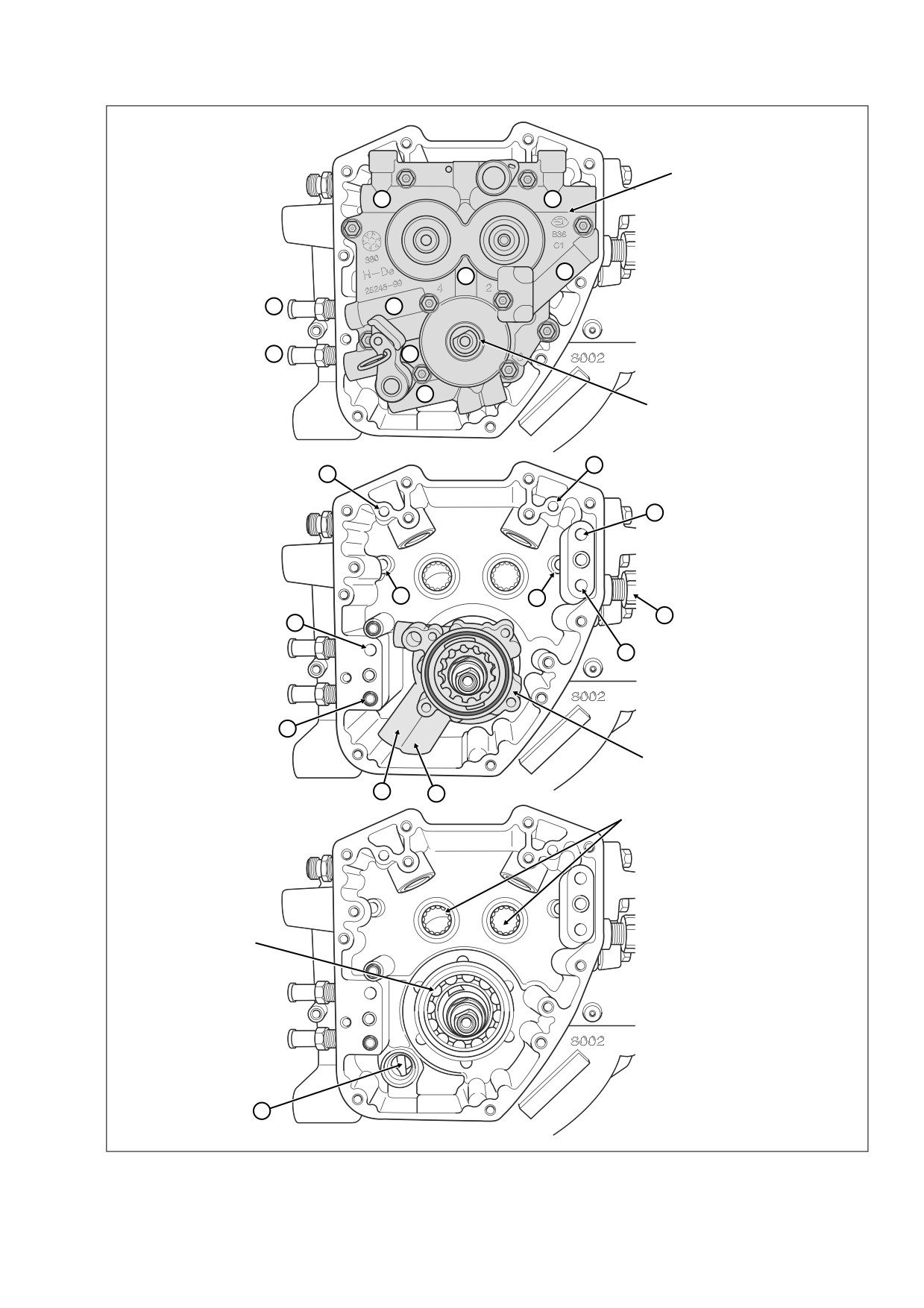
Oil Feed (Figures 3-6, 3-7)
Washers
Oil flows from the oil pan through a passageway at the front
of the transmission housing into a flexible hose clamped to
Figure 3-4. Oil Pressure Gauge
the lower fitting (A1) at the rear right side of the crankcase.
(Part No. HD-96921-52B)
Running through a passageway in the crankcase, the oil exits
a hole in the crankcase flange (B2) and enters a hole on the
f1646x3x
inboard side of the cam support plate. Passing through a
channel in the cam support plate (A3), the oil enters the feed
side of the oil pump. See OIL PUMP OPERATION. The feed
Adapter
gerotors of the pump direct the flow up a second channel in
the cam support plate (A4).
A drilling in this channel connects to a pressure relief valve
mounted in the bypass port of the cam support plate (A5).
When the oil pressure exceeds the setting of the valve spring
Oil
(35 psi), the orifice opens to bypass excess oil back to the
Filter
feed side of the pump (A3).
Oil not returned to the feed side exits a hole on the inboard
side of the cam support plate and passes through a hole in
the crankcase flange (B6). Flowing through a passageway in
the crankcase, where a reading is taken by the oil pressure
sender (B7), the oil exits the lower hole in the oil filter mount
(D8).
Figure 3-5. Install Adapter and Oil Pressure Gauge
After circulating through the oil filter, the flow of oil is directed
back into the crankcase through the upper hole in the oil filter
mount (D9). Exiting a passageway in the crankcase through
NOTE
a hole in the crankcase flange (B10), the flow of oil reenters
If reusing oil pressure switch/sender, apply Loctite Pipe Seal-
the cam support plate.
ant with Teflon 565 to threads.
Filtered oil is then routed to the top and bottom ends of the
11. Start oil pressure switch/sender into crankcase bore.
engine, as described below.
12. On FLHR/C/S models, use a 15/16 inch Open End Crow
Top End (Figures 3-6, 3-7)
Foot (Snap-On FC30B) to tighten oil pressure switch to
96-120 in-lbs (11-14 Nm). On FLHX, FLHT/C/U and
Oil passes through a channel in the cam support plate exiting
FLTR models, use 1-1/16 inch Open End Crow Foot
the inboard side through two holes near the top (A11, A12).
(Snap-On FC34A) to tighten oil pressure sender to same
Entering two holes in the crankcase flange (B13, B14), one
torque.
leading to the front cylinder and the other to the rear, the oil
travels through passageways in the crankcase to the hydrau-
13. On FLHR/C/S models, install elbow on post of oil pres-
sure switch. On FLHX, FLHT/C/U and FLTR models,
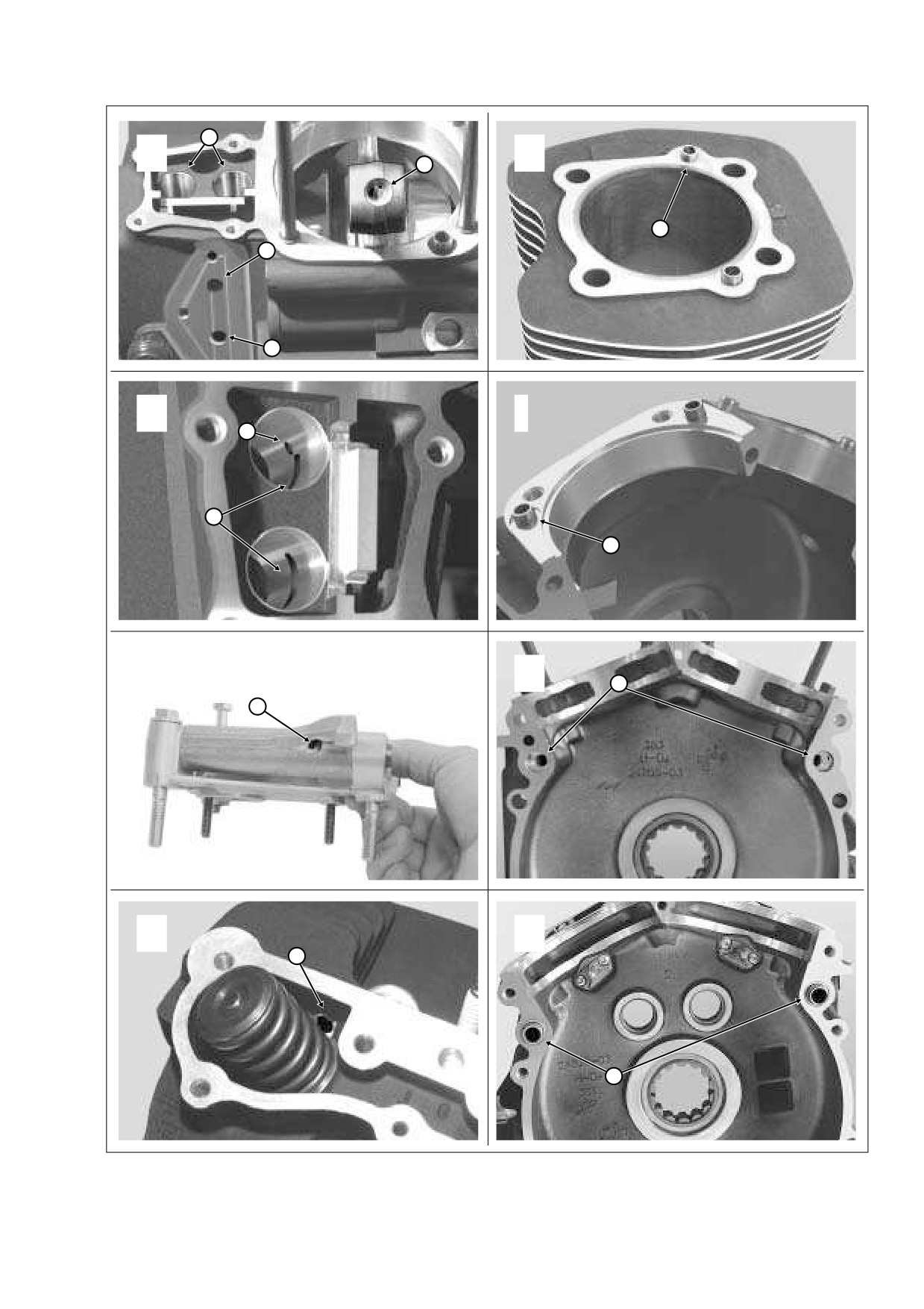
lic lifter bores (D15).
install Delphi connector to oil pressure sender.
Exiting a hole in each lifter bore (E16), the oil flows around
the lifter and enters a hole at the side of the lifter body. As the
NOTE
chamber inside the lifter body is filled, the push rod socket
If wire socket terminal requires replacement, see APPENDIX
rises to achieve the no-lash fit of the valve train components.
B.6 SEALED BUTT SPLICE CONNECTORS.
The flow of oil then exits a hole centered in the lifter socket
14. Test oil pressure switch/sender for proper operation.
and runs up the hollow push rods.
3-8
2006 Touring: Engine
HOME
f1581c3x
A
Cam Support Plate
12
11
4
26
38
36
1
3
5
Crankshaft
Bushing
13
14
10
B
24
23
7
37
6
2
f1573b3x
Oil Pump
35
25
Cam Needle Bearings
C
Crankshaft
Bearing
34
f1580b3x
Figure 3-6. Engine Oil Flow - Cam Support Plate/Right Crankcase Half
2006 Touring: Engine
3-9
HOME
NOTE
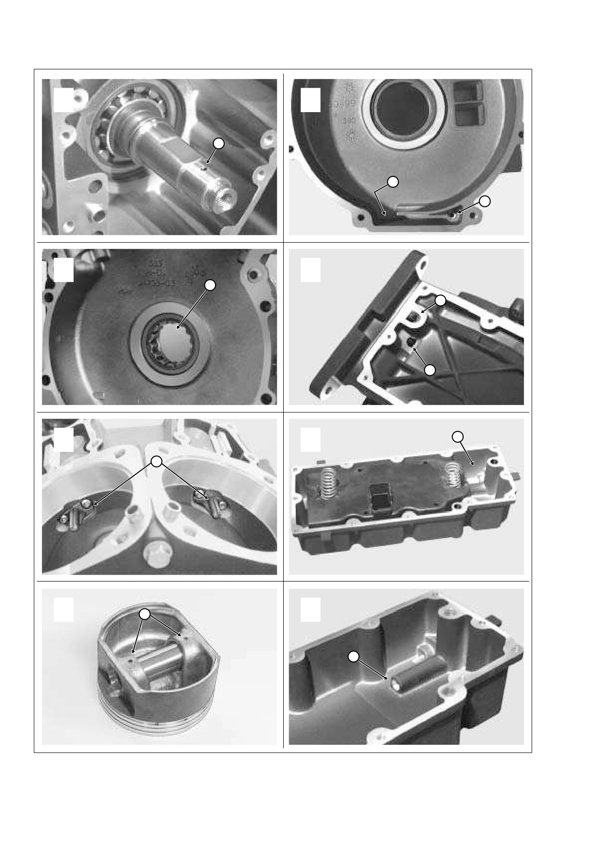
Oil spray from each piston jet also enters a hole at the bottom
Note that there is one additional hole drilled into the inside
of each pin boss (O30) for lubrication of the piston pin.
lifter bores- while the oblong hole circulates oil around the
Another hole at the top of the connecting rod (D31) allows a
lifter body as described, the round hole (E17) feeds oil to the
portion of the oil to reach the upper rod bushing.
piston jets in the flywheel compartment.
Surplus oil falls back to the bottom of the flywheel compart-
Exiting holes at the top of the hollow push rods, oil enters a
ment where it collects in the sump area (P32). Oil in the
hole at the bottom of the intake and exhaust rocker arms.
sump is drawn to the cam compartment through an internal
Lubricating the rocker arm bushings, oil flows down the
channel (P33, C34) that connects with the second scavenge
rocker arm shafts and exits a pin hole in the outboard side of
lobe of the oil pump (B35).
each rocker arm housing (F18) where it sprays the valve
springs and the top of the valve stem.
Oil Return (Figures 3-6, 3-8)
Oil runs down to the low side of the rocker housing and
enters the exhaust valve spring pocket where a drain hole
The “dual kidney” designation given to the oil pump refers to
(G19) leads to a passageway in the cylinder head casting.
its two scavenging functions, whereby it simultaneously
Oil exits the bottom of the cylinder head and passes through
draws oil from both the cam and flywheel compartments.
a ring dowel (H20) on the “down side” of the cylinder flange.
The oil runs through a vertical passageway in the cylinder,
Oil sucked up by the scavenge lobes passes through the
passes through a second ring dowel on the “down side” of
scavenge gerotors of the oil pump and is directed through a
the cylinder deck (I21) and enters the left crankcase half.
return channel in the cam support plate (A36). See OIL
PUMP OPERATION.
Flowing through a horizontal passageway in the left crank-
case half (J22), oil runs through a third ring dowel (K23) to
Exiting a hole on the inboard side of the cam support plate,
the right crankcase half where it travels through another pas-
the oil enters a hole in the crankcase flange (B37).
sageway before emptying into the cam compartment (B23,
B24).
The oil flows through a passageway in the crankcase and
Oil collecting in the cam compartment is picked up by one of
exits the upper fitting at the rear right side of the crankcase
two scavenge lobes on the oil pump (B25).
(A38). Passing through a flexible hose connection, the flow of
oil runs through a passageway at the front of the transmis-
Bottom End (Figures 3-6, 3-7, 3-8)
sion housing (Q39) before emptying into the oil pan at the
front of the baffle (R40).
Oil travels down the center passage of the cam support plate
(A26) and sprays out through pin holes on each side of the
The oil flows to the rear of the oil pan along each side of the
casting to lubricate both the primary and secondary cam
baffle. Spring tension holds the unit tight against the bottom
chains. Oil also passes through a hole in the crankshaft
bushing where the flow enters a drilling in the crankshaft
of the pan to prevent oil from entering or escaping around the
perimeter of the baffle. At the back of the oil pan, the oil
(L27).
enters the open side of the baffle where it is redirected for-
Oil runs down the center of the crankshaft and then up a
ward. The baffle plates slow the circulation of the oil through
cross drilling into the right side of the flywheel. The flow exits
the pan to enhance cooling.
a drilling in the crank pin bore, enters the crank pin and then
sprays out through three holes to lubricate the lower rod
Oil pickup occurs in the front compartment of the baffle
bearing set.
where a passageway in the casting (S41) directs the flow
The oil splash and mist created by the action of the flywheel
upward. Passing through a second passageway in the trans-
lubricates the crankshaft bearing and the camshaft needle
mission housing (Q42), the flow of oil enters the flexible hose
bearings in the right crankcase half. This same action serves
connection (A1) to repeat the circuit.
to lubricate the sprocket shaft bearing in the left crankcase
half (M28).
Also note that a third flexible hose clamped to a fitting behind
the rear lifter cover connects the cam compartment with the
Since the oil mist also lubricates the cylinder walls, three
oil filler spout. This crankcase breather connection provides
holes on each side of the piston (in the area of the third ring
the pressure balance necessary for oil circulation.
land) evacuate excess oil scraped from the walls on the pis-
ton downstroke.
Oil Pump Operation
The piston jets (N29), which receive a supply of oil from the
intake lifter bores, spray the underside of the piston for cool-
The oil pump consists of a housing containing two gerotor
ing of the piston crown and skirt area. A check valve in each
gear sets, one feed and the other scavenge. Driven by the
jet opens only when the oil pressure reaches 12-15 psi, at
crankshaft, the feed gerotor set distributes oil to the engine,
which point the engine is operating above idle speed. At idle
while the scavenge gerotor set draws oil from the cam and
speeds (9-12 psi), the valve remains closed to prevent over
flywheel compartments and returns it to the oil pan.
oiling and to ensure proper system operating pressure.
3-10
2006 Touring: Engine
HOME
15
D
31
H
20
9
8
E
I
17
16
21
F
J
22
18
G
K
19
23
Figure 3-7. Engine Oil Flow - Top End
2006 Touring: Engine
3-11
HOME
L
P
27
32
33
M
Q
28
42
39
40
N
R
29
O
30
S
41
Figure 3-8. Engine Oil Flow - Bottom End
3-12
2006 Touring: Engine
HOME
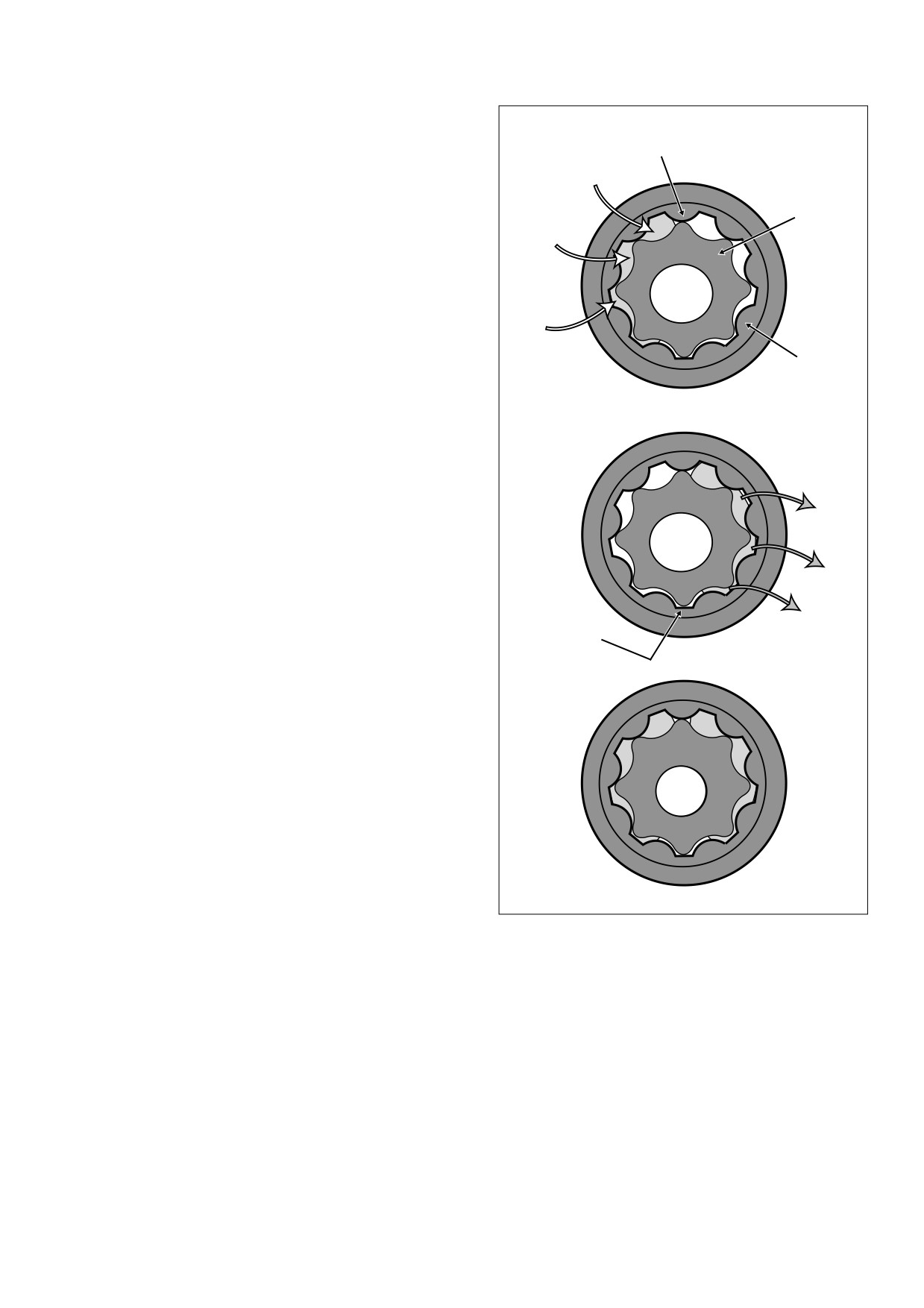
Each gerotor gear set has two parts, an inner and outer gero-
tor. The inner and outer gerotors have fixed centers that are
f1562x3x
slightly offset to one another. Also, the inner gerotor has one
Seal
less tooth.
As the crankshaft rotates, the cavity between the inner and
Inner
outer gerotors on the inlet side of the pump increases in vol-
Oil In
Gerotor
ume. This creates a vacuum causing oil to be drawn in. The
cavity continues to increase until the volume is equivalent to
that of the missing tooth on the inner gerotor. Also note that
the inlet and outlet sides of the pump are sealed by the tips
A
and lobes of the inner and outer gerotors. See A of Figure 3-
9.
Continued rotation moves the pocket of oil to the outlet side
of the pump. In this area, the cavity decreases in volume as
the gerotor teeth mesh causing the oil to be squeezed out the
Outer
discharge port. As the cavity on the outlet side is emptied, a
Gerotor
second seal formed by the tips and lobes of the inner and
outer gerotors prevents oil on the outlet side (high pressure)
from being transferred to the inlet side (low pressure). See B
of Figure 3-9.
In operation, the gerotors provide a continuous flow of oil.
See C of Figure 3-9.
Breather Operation
Oil Out
NOTE
B
The crankcase breather system relieves crankcase pressure
produced by the downstroke of the pistons and allows crank-
case vapors vacated from each cylinder to be directed into
the air filter element. Through effective recirculation of crank-
case vapors, the system serves to eliminate the pollutants
Seal
normally discharged from the crankcase.
As each piston pushes downward on its power and intake
stroke, displaced air in the flywheel compartment is vented
through the crankshaft bearing into the cam compartment
and then up the push rod covers into the rocker housing.
Air rushes under the rocker arm support plate, which is ele-
vated slightly, and passes through an opening at the bottom
of the plate to enter the breather baffle compartment.
C
In the baffle compartment, the flow of air passes upward
through the oil filter gauze, where the oil is removed from the
air. Two pin holes in the rocker arm support plate act as drain
holes to rid the baffle compartment of the oil separated from
the air.
Passing through the oil filter gauze, the flow of air passes
through the umbrella valve into the breather compartment.
Figure 3-9. Gerotor Operation
The flaps of the umbrella valve only allow air to be vented
one way, rising to allow the passage of air, but then falling
back into place to seal the vent holes as the flow of air stops.
Flowing
through the cylinder head passageway, the
air
passes through a drilling in the air cleaner backplate bolt and
In the breather compartment, the flow of air reverses direc-
then through a breather tube into the air filter element.
tion passing downward through holes aligned in the breather
baffle, rocker arm support plate and rocker housing. Exiting
NOTE
the rocker housing, the air enters a passageway cast into the
top of the cylinder head. Proper orientation of the rocker
Air cleaner mounting without installation of the breather
housing gasket is critical for effective sealing of this passage-
tubes allows crankcase vapors to be vented into the atmo-
way.
sphere in violation of legal emissions standards.
2006 Touring: Engine
3-13
HOME
HOW TO USE THIS SECTION
3.4
GENERAL
TOP END SERVICE
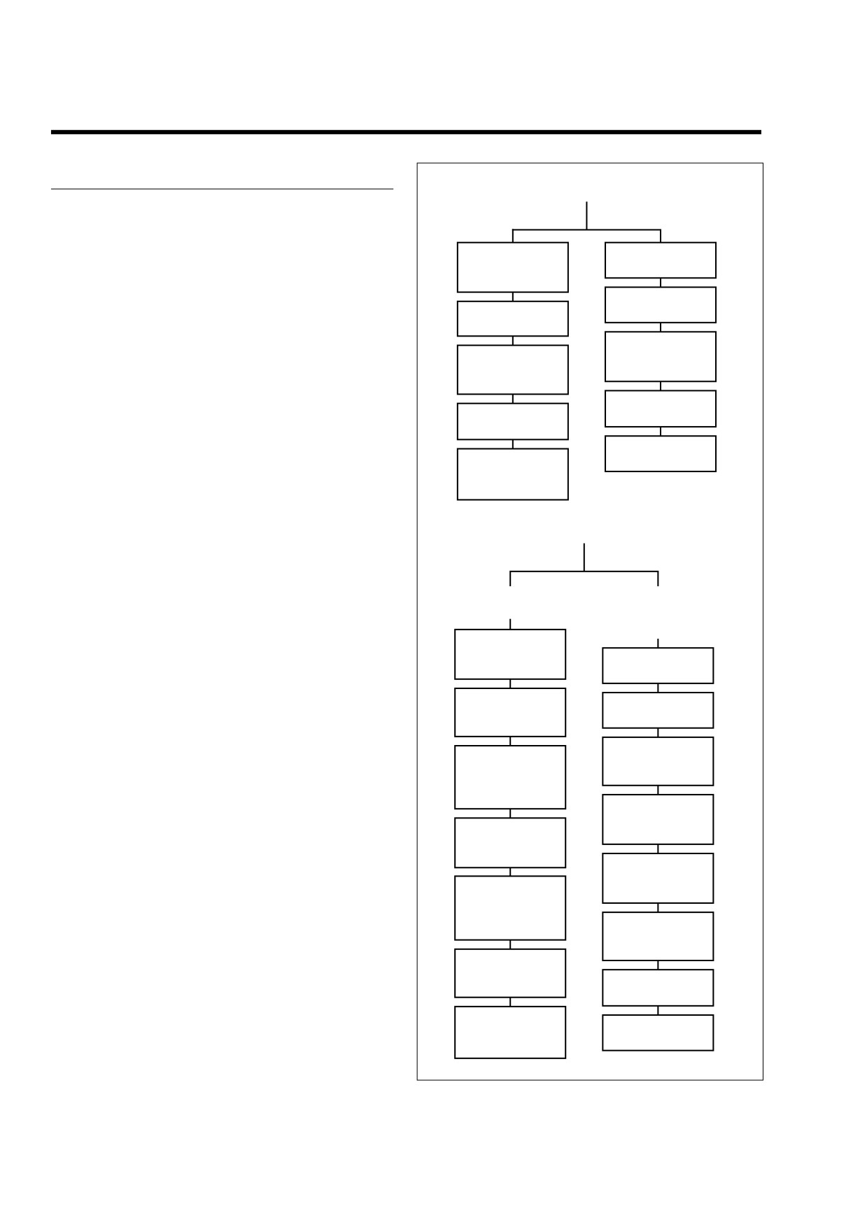
Three basic levels of service are presented in this section:
Engine in Chassis
Engine Removed
top end overhaul, bottom end overhaul and subassembly ser-
vice and repair. The manner in which these instructions are
used depends upon the level of disassembly required.
Stripping
Removing Engine
Motorcycle for
From Chassis.
Service.
Top End Overhaul
Top End Overhaul,
Top End Overhaul,
Disassembly.
If servicing only cylinder head components, pistons, cylinders
Disassembly.
and/or upper rod bushings, see Section 3.5 STRIPPING
Subassembly
MOTORCYCLE FOR SERVICE, and then proceed to Section
Subassembly
Service and Repair-
3.9 TOP END OVERHAUL, DISASSEMBLY. During top end
Service and Repair-
Top End.
disassembly, the engine may be left in the chassis for ser-
Top End.
vice.
Top End Overhaul,
Top End Overhaul,
Assembly.
NOTE
Assembly.
If the engine is to be removed from the chassis, see Section
Installing Engine
3.7 REMOVING ENGINE FROM CHASSIS in lieu of Section
Assembling
In Chassis.
3.5 STRIPPING MOTORCYCLE FOR SERVICE.
Motorcycle After
In the top end disassembly instructions, references are made
Stripping.
to Section 3.11 SUBASSEMBLY SERVICE AND REPAIR for
service of all top end subassemblies.
BOTTOM END SERVICE
To rebuild the engine after a top end overhaul is complete,
perform the steps under Section 3.9 TOP END OVERHAUL,
Engine in Chassis
Engine Removed
ASSEMBLY, immediately following the disassembly instruc-
tions. Then, refer to Section 3.6 ASSEMBLING MOTORCY-
Cam
Flywheel Compartment
CLE AFTER STRIPPING to complete the project.
Compartment.
or Complete Engine
Overhaul.
NOTE
Stripping
For clarity, all artwork in this section shows the engine
Motorcycle for
removed from the chassis for service.
Removing Engine
Service.
From Chassis.
Top End Overhaul,
Bottom End Overhaul
Top End Overhaul,
Disassembly,
Disassembly.
Bottom end service may require either partial or complete
Steps 1-11.
disassembly of the engine. Servicing components in the cam
Bottom End
Bottom End
compartment requires only partial disassembly, while servic-
Overhaul,
Overhaul,
ing those in the flywheel compartment requires complete dis-
Disassembly.
Disassembly,
assembly. An easy rule to remember is that any time the
Steps 1-14.
crankcase halves must be split, complete disassembly needs
Subassembly
Service and Repair-
to occur. The cam compartment can be accessed through
Subassembly
Top End.
removal of the cam cover making complete engine disassem-
Service and Repair-
bly unnecessary.
Bottom End.
Subassembly
During bottom end service that requires complete disassem-
Service and Repair-
Bottom End
bly, the engine must be removed from the chassis and placed
Bottom End.
Overhaul,
in an engine stand. To begin, see Section 3.7 REMOVING
Assembly,
ENGINE FROM CHASSIS.
Bottom End
Steps 12-29.
Overhaul,
After the motorcycle has been stripped and the engine
Assembly.
removed, follow all of the steps under Section 3.9 TOP END
Top End Overhaul,
Assembly,
OVERHAUL, DISASSEMBLY. When finished, continue with
Top End Overhaul,
Steps 29-39.
disassembly of the bottom half by performing those steps
Assembly.
listed under Section 3.10 BOTTOM END OVERHAUL, DIS-
Assembling
ASSEMBLY.
Installing Engine
Motorcycle After
In Chassis.
Stripping.
Figure 3-10. Top/Bottom End Service
3-14
2006 Touring: Engine
HOME
As with the top end disassembly instructions, references are
For example, if just installing new cams, then refer to Section
made to Section
3.11 SUBASSEMBLY SERVICE AND
3.11 SUBASSEMBLY SERVICE AND REPAIR, CAM SUP-
REPAIR for service of bottom end subassemblies.
PORT PLATE.
Since it is standard practice to inspect and clean all oil pas-
The steps under Section 3.9 TOP END OVERHAUL and Sec-
sages when the engine is completely disassembled, a
tion 3.10 BOTTOM END OVERHAUL that need to be fol-
detailed explanation of the engine oil circuit is presented
lowed for the removal and installation of the cam support
under Section 3.3 GENERAL INFORMATION, ENGINE OIL
plate are given.
FLOW.
Furthermore, detailed instructions for disassembling, clean-
To rebuild the engine after a bottom end overhaul is com-
ing, inspecting, replacing and assembling cam support plate
plete, perform the steps under Section 3.10 BOTTOM END
components are provided.
OVERHAUL, ASSEMBLY, and then proceed to Section 3.9
TOP END OVERHAUL, ASSEMBLY, to rebuild the upper
end.
Once the engine is assembled, refer to Section 3.8 INSTALL-
ING ENGINE IN CHASSIS to complete the project.
The flow charts on the preceding page show how the same
subsections are used for various levels of service.
Subassembly Service and Repair
Finally, if the task entails servicing of only one particular sub-
assembly, then move directly to Section 3.11 SUBASSEM-
BLY SERVICE AND REPAIR for all service instructions.
2006 Touring: Engine
3-15
HOME
STRIPPING MOTORCYCLE FOR SERVICE
3.5
e. Tape free ends of wire harness to top of wire har-
PROCEDURE
ness trough on frame backbone to keep conduit and
connectors out of the way.
NOTE
If performing top end service (or both cam compartment and
9.
Remove idle and throttle control cables as follows:
top end), follow steps 1-16. If servicing cam compartment
Carbureted: Using a needle nose pliers, carefully pull
components only, perform steps 1-7.
idle cable barrel from upper inboard hole in throttle
1.
Remove the exhaust system in two sections. See Sec-
wheel. Pull throttle cable barrel from remaining hole.
tion 2.38 EXHAUST SYSTEM, REMOVAL.
Release idle and throttle cables from guides in throttle
cable bracket.
2.
Remove the air cleaner and backplate. See Section 4.5
AIR CLEANER, REMOVAL.
Fuel Injected: Using a needle nose pliers, carefully pull
3.
Drain and remove fuel tank. Proceed as follows:
idle cable barrel from upper hole in throttle wheel. Pull
throttle cable barrel from lower hole. Using slots, release
Carbureted: See Section 4.7 FUEL TANK (CARBU-
idle and throttle cables from guides in throttle cable
RETED), COMPLETE REMOVAL, FLHX, FLHT, or
bracket.
FLHR/S.
Fuel Injected: See Section
9.4 FUEL TANK (FUEL
10.
Free idle and throttle control cables from J-clamp fas-
INJECTED), COMPLETE REMOVAL, FLHXI, FLHT/C/
tened to right side of frame backbone. Move cables up
U/I, FLTRI, or FLHR/C/S/I.
and out of the way.
4.
Moving to left side of motorcycle, pull boots on spark
11.
If equipped with cruise control, remove E-clip from
plug cables to release from spark plug and ignition coil
sleeve at end of cruise cable housing. Using slot,
towers. Release cables from three cable clips at bottom
remove cable housing from cable guide in throttle cable
of frame backbone.
bracket. Push the plastic end fitting on the cruise cable
to the outboard side to release from wheel pin. Move
5.
Remove spark plugs.
cable up and out of the way.
6.
Disconnect ignition coil connector [83] from left side of
12.
Remove intake manifold/carburetor or induction module.
ignition coil.
Proceed as follows:
7.
Pull sides of ignition coil bracket outward to remove from
bosses of front fuel tank mount.
a. Remove right side allen head socket screws from
front and rear cylinder head flange adapters. For
8.
Remove connections to carburetor or induction module.
best results, use the INTAKE MANIFOLD WRENCH
Proceed as follows:
(HD-47250), or a long
1/4 inch ball allen head
Carbureted:
socket with end driver 4 inches long.
a. Standing on left side of motorcycle, remove MAP
b. Moving to opposite side of motorcycle, just loosen
sensor connector [80] at top of intake manifold.
left side allen head socket screws from flange
adapters. Slots in flanges make removal of left side
b. Locate the fuel enrichener knob under the left side
screws unnecessary.
of the fuel tank, and loosen hex nut at backside of
mounting bracket. Slide cable assembly free of slot
c. Remove intake manifold/carburetor or induction
in mounting bracket.
module from right side of motorcycle.
Fuel Injected:
13.
Standing on left side of motorcycle, remove two hex
a. Standing on right side of motorcycle, remove IAC
head bolts (with flat washers) to release top engine
connector [87] and MAP sensor connector [80].
mounting bracket from cylinder heads.
b. Remove front fuel injector connector [84] and rear
14.
Leaving ground wire ring terminal in place, detach
fuel injector connector [85].
socket terminal of yellow lead from spade contact at
c. Remove TP sensor connector [88] and IAT sensor
back of horn. Release wire conduit from J-clamp.
connector [89].
15.
Moving to right side of motorcycle, turn hex head bolt to
d. Moving to left side of motorcycle, pull back boot at
release stabilizer link from frame weldment.
back of front cylinder and remove ET sensor con-
nector [90]. Cut cable strap to release conduit from
16.
Remove horn, top engine mounting bracket and stabi-
horn bracket.
lizer link as an assembly.
3-16
2006 Touring: Engine
HOME
ASSEMBLING MOTORCYCLE AFTER STRIPPING
3.6
c. Standing on left side of motorcycle, install two hex
PROCEDURE
head bolts (with flat washers) to secure top engine
mounting bracket to front and rear cylinder heads.
NOTE
Alternately tighten bolts to 35-40 ft-lbs (48-54 Nm).
If top end service was performed (or both cam compartment
and top end), follow steps 1-13. If only cam compartment
3.
If equipped with cruise control, slide groove in cruise
components were serviced, perform steps 8-12.
cable end fitting over cap of wheel pin. Push on end fit-
ting until it snaps in place. Using slot, slip cruise cable
1.
Install intake manifold/carburetor or induction module.
housing into cable guide in throttle cable bracket. Install
Proceed as follows:
new E-clip on sleeve at end of cruise cable housing.
a.
With the counterbore facing outward, slide cylinder
4.
Route idle and throttle control cables through J-clamp
head flange adapters onto outlet ports of intake
fastened to right side of frame backbone.
manifold/induction module. The flange adapters are
not interchangeable. Look next to the slotted bolt
5.
Install idle and throttle control cables as follows:
hole for a stamp that indicates F(ront) and R(ear)
Carbureted: Install sleeve on throttle cable housing into
cylinder.
shorter cable guide in throttle cable bracket. Drawing
b.
Place a new seal in each flange adapter with the
throttle cable downward, fit barrel end into lower out-
beveled side in against the counterbore.
board hole in throttle wheel. Install sleeve and spring on
idle cable housing into longer cable guide inserting bar-
c.
Standing on right side of engine, slide intake mani-
rel end into upper inboard hole in throttle wheel.
fold/induction module toward installed position so
that open-ended slots on flange adapters begin to
Induction Module:Install sleeve on throttle cable hous-
engage allen head socket screws loosely installed
ing into shorter cable guide at top of throttle cable
on left side.
bracket. Drawing throttle cable downward, fit barrel end
d.
Align fixed holes in flange adapters with those in
into lower hole in throttle wheel. Install sleeve and spring
on idle cable housing into longer cable guide at bottom
cylinder heads and start allen head socket screws.
of throttle cable bracket inserting barrel end into upper
For best results, use the INTAKE MANIFOLD
hole in throttle wheel.
WRENCH (HD-47250), or a long 1/4 inch ball allen
head socket with end driver 4 inches long.
6.
Adjust cables as necessary to keep barrel ends from dis-
e.
Use the air cleaner backplate to properly locate car-
lodging. Verify that cables are seated in channel of throt-
buretor/induction module. Install two breather bolts
tle wheel. Verify operation by turning throttle grip and
to fasten backplate to front and rear cylinder heads.
observing cable action.
Install three T27 TORX screws to secure backplate
7.
Install connections to carburetor or induction module.
to face of carburetor/induction module.
Standing on left side of motorcycle, proceed as follows:
f.
Tighten allen head socket screw in fixed holes of
Carbureted:
flange adapters until snug. Moving to left side of
engine, tighten screws in slotted holes to 96-144 in-
a. Moving to left side of motorcycle, install MAP sensor
lbs (10.9-16.3 Nm).
connector [80] at top of intake manifold.
g.
Remove breather bolts and T27 TORX screws to
b. Slide threaded portion of enrichener cable into slot
remove backplate.
of mounting bracket. Flat on threads must face rear
of motorcycle for script on enrichener knob to be
h.
Tighten allen head socket screws in fixed holes of
right side up. With the external tooth lockwasher
flange adapters to 96-144 in-lbs (10.9-16.3 Nm).
and hex nut positioned on the inboard side of the
mounting bracket, tighten hex nut to 20-35 in-lbs
2.
Install horn, top engine mounting bracket and stabilizer
(2.3-4.0 Nm).
link as an assembly. Proceed as follows:
a. Moving to right side of motorcycle, turn hex head
Fuel Injected:
bolt to secure stabilizer link to frame weldment.
Tighten bolt to 18-22 ft-lbs (24-30 Nm).
a. Install rear fuel injector connector [85] and front fuel
injector connector [84].
b. Attach socket terminal of yellow lead to spade con-
tact at back of horn. Capture wire conduit in J-
b. Install MAP sensor connector [80] and IAC connec-
clamp.
tor [87].
2006 Touring: Engine
3-17
HOME
c. Install IAT sensor connector [89] and TP sensor
10.
Install the fuel tank. Proceed as follows:
connector [88].
Carbureted: See Section 4.7 FUEL TANK (CARBU-
d. Moving to left side of motorcycle, install ET sensor
RETED), INSTALLATION
(AFTER COMPLETE
connector [90] at back of front cylinder. Pull boot
REMOVAL), FLHX, FLHT, or FLHR/S.
over sensor to keep out dirt and debris. Install new
Fuel Injected: See Section
9.4 FUEL TANK (FUEL
cable strap to secure connector conduit to horn
INJECTED), INSTALLATION
(AFTER COMPLETE
bracket.
REMOVAL), FLHXI, FLHT/C/U/I, FLTRI, or FLHR/C/S/I.
8.
Install spark plugs in front and rear cylinder heads.
11.
Install the backplate and air cleaner. See Section 4.5
Install the plugs finger tight and then tighten to 12-18 ft-
AIR CLEANER, INSTALLATION.
lbs (16-24 Nm).
12.
Install the exhaust system. See Section 2.38 EXHAUST
9.
Install ignition coil and spark plug cables as follows:
SYSTEM, INSTALLATION.
a. With the coil towers facing rear of vehicle, hold igni-
13.
Adjust idle and throttle control cables as follows:
tion coil and bracket at bottom of frame backbone.
Pull sides of bracket outward and install on bosses
Non-Cruise: See Section 2.21 THROTTLE CABLES
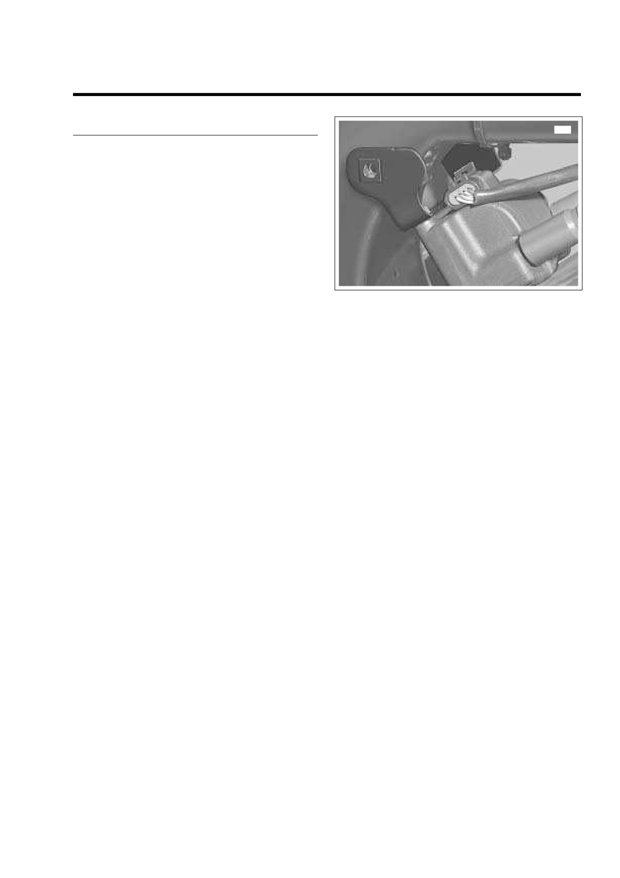
of front fuel tank mount. See Figure 3-11.
(NON-CRUISE), ADJUSTMENT.
b. Connect ignition coil connector [83] to left side of
Cruise Equipped: See Section 8.31 CRUISE CON-
ignition coil.
TROL (FLHRC, FLHTCU, FLTR), CABLE ADJUST-
MENT.
c. Install spark plug cable to front cylinder onto left
side coil tower. Verify that spark plug cable is cap-
tured in double-sided cable clip at bottom left side of
frame backbone. Install new cable clip on T-stud if
damaged or missing.
d. Install spark plug cable to rear cylinder onto right
side coil tower. Verify that spark plug cable is cap-
tured in two single-sided cable clips at bottom left
side of frame backbone. Install new cable clips on T-
studs if damaged or missing.
3-18
2006 Touring: Engine
HOME
REMOVING ENGINE FROM CHASSIS
3.7
PROCEDURE
8316
1.
Remove the exhaust system in two sections. See Sec-
tion 2.38 EXHAUST SYSTEM, REMOVAL.
2.
Remove the air cleaner and backplate. See Section 4.5
AIR CLEANER, REMOVAL.
3.
Drain and remove fuel tank. Proceed as follows:
Carbureted: See Section 4.7 FUEL TANK (CARBU-
RETED), COMPLETE REMOVAL, FLHX, FLHT, or
FLHR/S.
Fuel Injected: See Section
9.4 FUEL TANK (FUEL
INJECTED), COMPLETE REMOVAL, FLHXI, FLHT/C/
U/I, FLTRI, or FLHR/C/S/I.
Figure 3-11. Remove Ignition Coil Bracket
4.
Remove the primary chaincase. See Section 6.5 PRI-
MARY CHAINCASE, REMOVAL.
5.
Remove connections to carburetor or induction module.
Fuel Injected: Using a needle nose pliers, carefully pull
idle cable barrel from upper hole in throttle wheel. Pull
Proceed as follows:
throttle cable barrel from lower hole. Using slots, release
Carbureted:
idle and throttle cables from guides in throttle cable
bracket.
a. Moving to left side of motorcycle, remove MAP sen-
sor connector [80] at top of intake manifold.
7.
Free idle and throttle control cables from J-clamp fas-
b. Locate the fuel enrichener knob under the left side
tened to right side of frame backbone. Move cables up
of the fuel tank, and loosen hex nut at backside of
and out of the way.
mounting bracket. Slide cable assembly free of slot
8.
If equipped with cruise control, remove E-clip from
in mounting bracket.
sleeve at end of cruise cable housing. Using slot,
Fuel Injected:
remove cable housing from cable guide in throttle cable
bracket. Push the plastic end fitting on the cruise cable
a. Standing on right side of motorcycle, remove IAC
to the outboard side to release from wheel pin. Move
connector [87] and MAP sensor connector [80].
cable up and out of the way.
b. Remove front fuel injector connector [84] and rear
9.
Moving to left side of motorcycle, pull boots on spark
fuel injector connector [85].
plug cables to release from spark plug and ignition coil
towers. Release cables from three cable clips at bottom
c. Remove TP sensor connector [88] and IAT sensor
of frame backbone.
connector [89].
10.
Remove spark plugs.
d. Moving to left side of motorcycle, pull back boot at
back of front cylinder and remove ET sensor con-
11.
Disconnect ignition coil connector [83] from left side of
nector [90]. Cut cable strap to release conduit from
ignition coil.
horn bracket.
12.
Pull sides of ignition coil bracket outward to remove from
e. Tape free ends of wire harness to top of wire har-
bosses of front fuel tank mount. See Figure 3-11.
ness trough on frame backbone to keep conduit and
13.
Moving to right side of motorcycle, remove two allen
connectors out of the way.
head socket screws to release oil hose cover.
6.
Remove idle and throttle control cables as follows:
14.
Using a side cutters, cut and remove clamps on engine
side of oil hoses. Pull hoses from crankcase fittings.
Carbureted: Using a needle nose pliers, carefully pull
idle cable barrel from upper inboard hole in throttle
15.
Cut and remove clamp on breather hose behind rear
wheel. Pull throttle cable barrel from remaining hole.
lifter cover. Pull hose from crankcase fitting and tuck
Release idle and throttle cables from guides in throttle
behind transmisson to engine flange to keep out of the
cable bracket.
way.
2006 Touring: Engine
3-19
HOME
22. Remove elbow terminals from spade contacts at back of
horn. Release wire harness conduit from J-clamp.
23. Moving to right side of motorcycle, turn hex head bolt to
release stabilizer link from frame weldment.
24. Remove horn, top engine mounting bracket and stabi-
lizer link as an assembly.
25. Remove four bolts (with flat washers) to free rear of
crankcase from transmission housing. Loosen and
remove bolts in a crosswise pattern.
26. Remove two bolts (with flat washers) to free front of
crankcase from front engine mounting bracket.
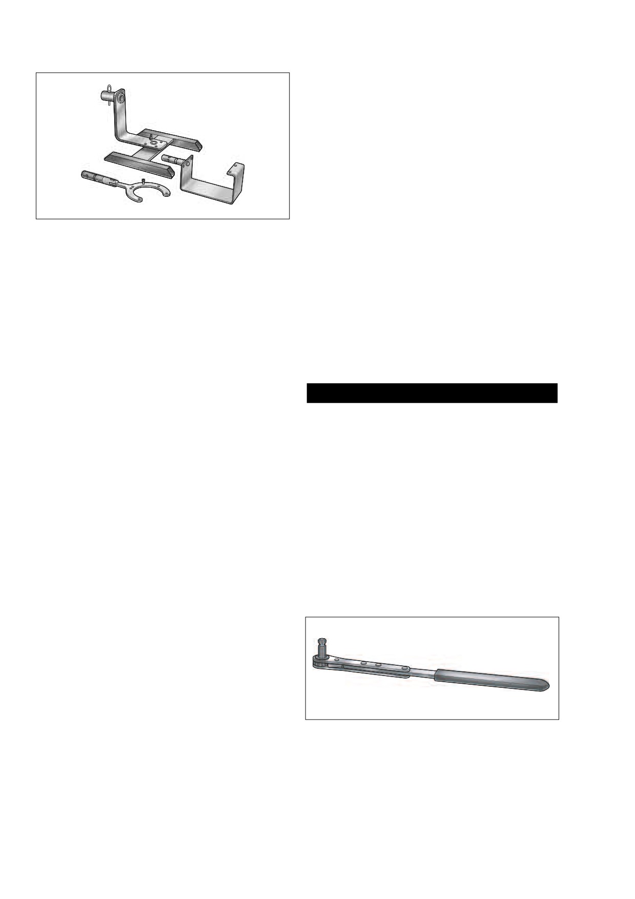
Figure 3-12. Engine/Transmission Bench Stand
27. Wrap rear master cylinder reservoir with foam padding
(Part No. HD-42310)
or bubble pack.
28. Cover lower frame tubes (both left and right side) with
16.
Remove the voltage regulator. See Section 8.9 VOLT-
foam padding or bubble pack. Split loom conduit or a half
AGE REGULATOR, REMOVAL.
shell of PVC tubing will also produce good results. Pro-
17.
Draw cables and socket of stator connector [46], 3-place
tection is necessary to prevent nicks or paint damage to
Lyall, to rear of front engine stabilizer link and then up to
left frame tube and chafing, cutting or kinking of the
area in front of primary chaincase.
brake line, wire cables and conduit at the top of the right
frame tube.
18.
Remove CKP sensor and oil pressure switch/sender as
follows:
29. Cover rocker covers of front and rear cylinders with foam
padding or bubble pack.
a. Locate CKP sensor connector [79], 2-place Deut-
sch, next to oil filter mount. Depress button on
socket terminal side and pull apart pin and socket
1CAUTION
halves.
The engine weighs approximately 165 pounds (74.8 kg).
b. Remove allen head socket screw to free crank posi-
Use a suitable lifting device, if necessary. Exercise cau-
tion sensor mount from crankcase. Pull sensor from
tion to avoid personal injury.
bore. Remove O-ring from groove on sensor body.
Discard O-ring.
30. Move engine forward far enough to clear two ring dowels
c. Locate the oil pressure switch/sender at the front
in lower flange of transmission housing. Raise engine
right side of the crankcase. On FLHR/C/S models,
and remove from right side of motorcycle. Exercise cau-
pull elbow from post of oil pressure switch. On
tion to avoid contact with rear brake master cylinder res-
FLHX, FLHT/C/U and FLTR models, pull external
ervoir and brake line, wire cables and conduit at top of
latch outward and use rocking motion to remove
lower frame tube.
Delphi connector from oil pressure sender.
31. Using the TWIN CAM 88 CRADLE (HD-42310-2), install
d. On FLHR/C/S models, use a 15/16 inch Open End
engine in BENCH STAND (HD-42310) or ROLLING
Crow Foot (Snap-On FC30B) to remove oil pressure
STAND (HD-43646A). See Figure 3-12.
switch from crankcase. On FLHX, FLHT/C/U and
32. Remove intake manifold/carburetor or induction module.
FLTR models, use 1-1/16 inch Open End Crow Foot
Proceed as follows:
(Snap-On FC34A) to remove oil pressure sender.
19.
Coil main harness conduit and allow to hang below
lower frame tube at front of motorcycle. If harness is not
moved out of the way, it may be damaged during engine
removal.
20.
Place jack under oil pan at rear of motorcycle. Using a
block of wood to distribute pressure across the length of
the casting, raise the jack until firm contact is made with
the bottom of the oil pan.
21.
Standing on left side of motorcycle, remove two hex
head bolts (with flat washers) to release top engine
Figure 3-13. Intake Manifold Wrench
mounting bracket from cylinder heads.
(Part No. HD-47250)
3-20
2006 Touring: Engine
HOME
34.
Remove stator as follows:
2
4
a. Remove four T27 TORX screws to free stator from
crankcase. Discard screws.
b. Using point of awl, carefully lift capped rib on grom-
met away from crankcase and then insert into bore
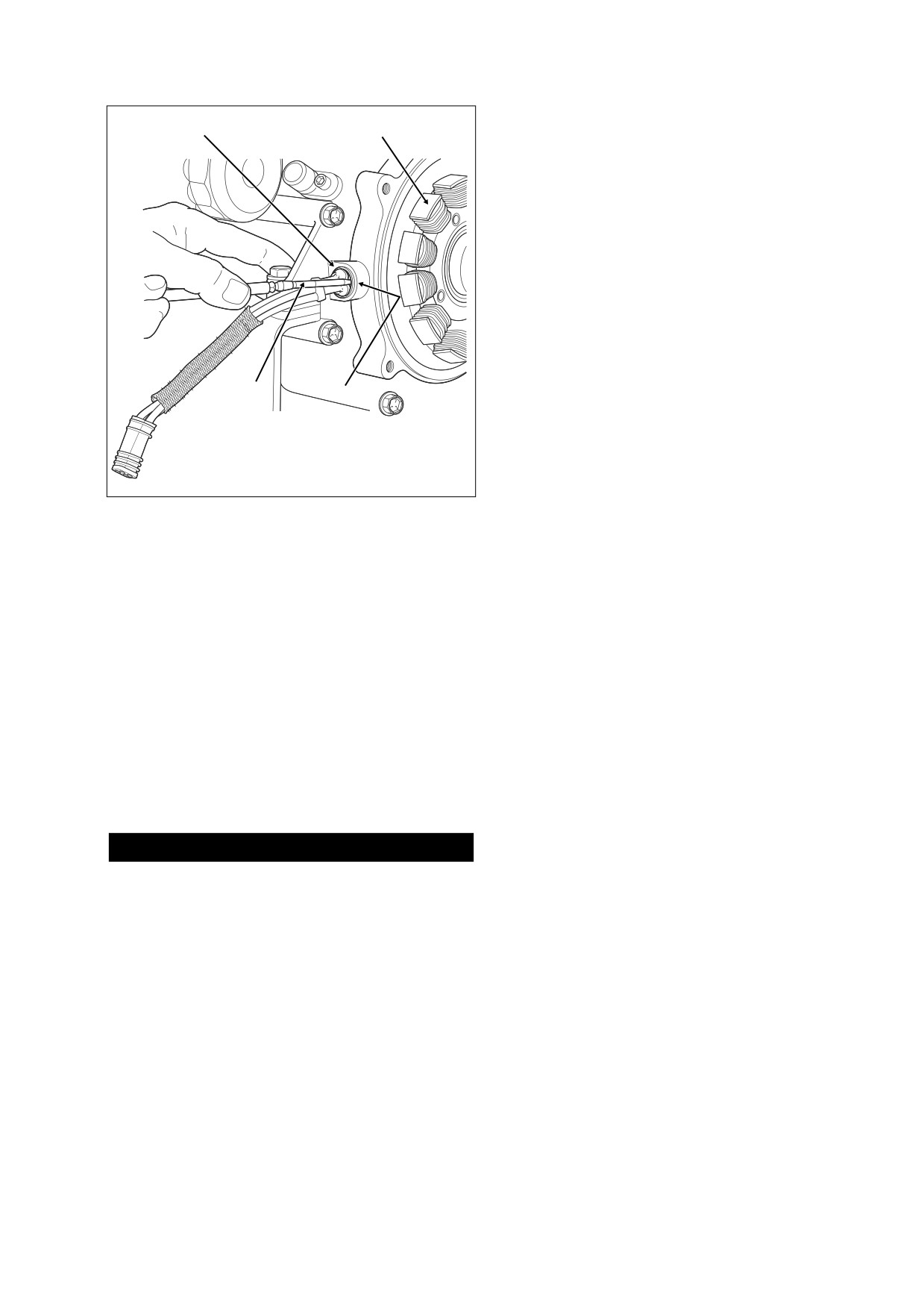
between grommet and casting. See Figure 3-14. Tilt
awl slightly squirting isopropyl alcohol or glass
cleaner into opening. Repeat this step at one or two
other locations around grommet.
c. While pushing on capped rib from outside of crank-
case, draw grommet through bore by pulling on
cable stop with needle nose pliers. Rock grommet
back and forth to facilitate removal, if necessary.
Exercise caution to avoid damaging ribs on grom-
met if stator is to be reused.
1
3
d. Draw stator cables and socket through crankcase
bore.
f2415x8x
35.
Remove the oil filter as follows:
1.
Awl
3.
Opening
a. Obtain the OIL FILTER WRENCH (HD-42311). The
2.
Capped Rib
4.
Stator
tool allows easy removal of the oil filter without risk
Figure 3-14. Remove Grommet From Crankcase
of damage to the CKP sensor or cable.
b. Place the jaws of the wrench over the oil filter with
the tool oriented vertically.
a. Remove right side allen head socket screws from
front and rear cylinder head flange adapters. For
c. Using a 3/8 inch drive with a 4 inch extension, turn
best results, use the INTAKE MANIFOLD WRENCH
wrench in a counterclockwise direction until loose.
(HD-47250), or a long
1/4 inch ball allen head
Do not use with air tools.
socket with end driver 4 inches long. See Figure 3-
NOTE
13.
Use OIL FILTER WRENCH (HD-44067) if HD-42311 is not
b. Moving to opposite side of motorcycle, just loosen
available.
left side allen head socket screws from flange
adapters. Slots in flanges make removal of left side
36. Remove oil filter mount as follows:
screws unnecessary.
a. Carefully bend corners on lockplate away from
c. Remove intake manifold/carburetor or induction
heads of top and bottom bolts in oil filter mount.
module from right side of motorcycle.
Remove top and bottom bolts, lockplate and flat
washers. Discard lockplate.
33.
Remove the rotor as follows:
b. Remove middle bolt with flat washer to free filter
mount from crankcase.
1CAUTION
c. Remove two O-rings from inboard side of filter
mount. Discard O-rings.
The high-output rotor contains powerful magnets. Use
the ROTOR REMOVER/INSTALLER and SHAFT PROTEC-
NOTES
TOR SLEEVE (HD-41771) to prevent parts damage and
possible hand injury during removal and installation.
Remove and clean the oil pan under any of the following con-
ditions:
a. Verify that threads of engine sprocket shaft are
clean, especially of old Loctite material. Thread the
● Metal debris is found in the engine or crankcase.
Shaft Protector Sleeve onto the shaft.
● Oil contamination is suspected.
b. Turn thumbscrews of Rotor Remover/Installer into
threaded holes in rotor face.
● A complete engine overhaul is being performed as a
result of a major engine failure.
c. Rotate handle of forcing screw in a clockwise direc-
tion to remove rotor from shaft.
● The engine is being replaced with a new one.
2006 Touring: Engine
3-21
HOME
f2025x3x
RIGHT SIDE
LEFT SIDE
Strap
Strap
Frame
Backbone
Mainshaft
Hook
Rubber Coated
Hook
Transmission
Rubber Coated
Bracket
f1791x2x
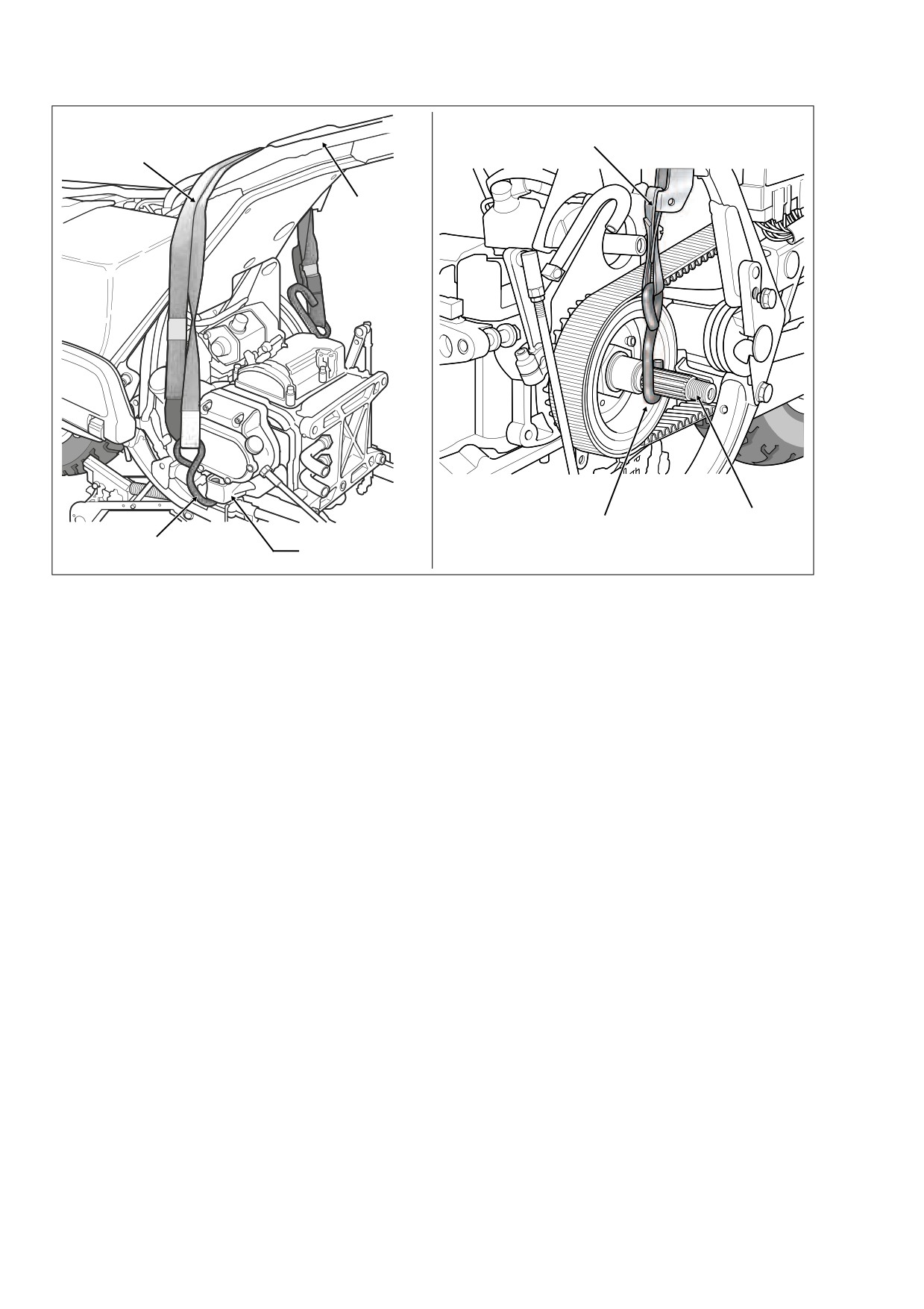
Figure 3-15. Secure Transmission Using Transmission Exhaust Bracket and Mainshaft
37. To remove the oil pan, proceed as follows:
d.
Locate transmission drain plug on right side of the
oil pan. See Figure 3-16. Remove the plug and
a. Use a tie down strap to hold the transmission. Lay
drain the transmission lubricant into a suitable con-
strap over frame backbone placing one rubber
tainer.
coated hook through the transmission exhaust
bracket on the right side of the motorcycle and the
e.
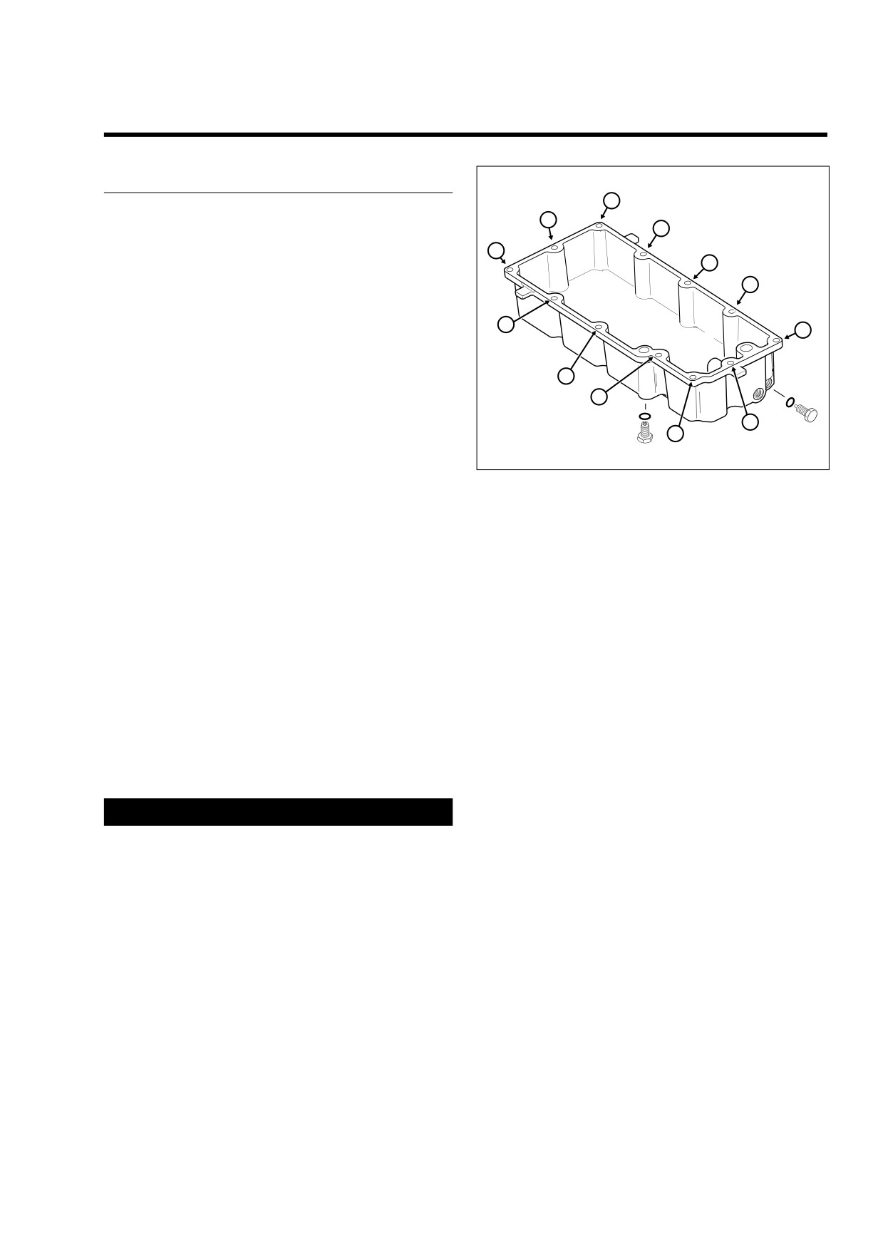
Alternately loosen and then remove the twelve allen
other around the mainshaft on the left. Using
head socket screws to release the oil pan from the
buckle, tighten strap until taut. See Figure 3-15.
transmission housing. Follow the pattern shown in
Figure 3-16.
b. Lower and remove jack under oil pan.
f.
Remove gasket from oil pan and discard.
c. Locate oil drain plug at front of the oil pan. See Fig-
ure 3-16. Remove the plug and allow oil to drain
completely.
3-22
2006 Touring: Engine
HOME
INSTALLING ENGINE IN CHASSIS
3.8
PROCEDURE
f1677x3x
9
11
NOTE
3
If oil pan was drained and removed, start at step 1. If oil pan
LEFT
7
was neither drained nor removed, move to step 13.
2
SIDE
6
1.
Coat gasket surface of oil pan with a thin coat of HYLO-
MAR® gasket sealer.
5
8
2.
Place gasket on oil pan and allow sealer to dry until
tacky.
3.
Position oil pan under transmission housing and start the
RIGHT
1
twelve allen head socket screws. Tighten each screw
SIDE
4
about two turns after initial thread engagement.
12
4.
Inspect the oil pan gasket to verify that it is properly posi-
Transmission
10
Engine Oil
Drain Plug
Drain Plug
tioned.
5.
Alternately tighten oil pan screws to 84-132 in-lbs (9.5-
Figure 3-16. Oil Pan Torque Sequence
14.9 Nm) following the pattern shown in Figure 3-16.
6.
Remove any foreign material from magnet of oil drain
plug. Also check the O-ring for tears, cuts or general
Use only Harley-Davidson FORMULA+ TRANSMIS-
deterioration. Replace as necessary.
SION AND PRIMARY CHAINCASE LUBRICANT, Part
No. 99851-05 (quart).
7.
Install the engine oil drain plug in front of the oil pan.
Tighten plug to 14-21 ft-lbs (19-28 Nm).
12.
Install the transmission filler plug/dipstick in the clutch
release cover. Tighten the plug to 25-75 in-lbs (2.8-8.5
8.
Remove the transmission filler plug from the clutch
Nm).
release cover on the right side of the transmission case.
Check the O-ring for tears, cuts or general deterioration.
13.
Place jack under oil pan at rear of motorcycle. Using a
Replace as necessary.
block of wood to distribute pressure across the length of
the casting, raise the jack until firm contact is made with
9.
Remove any foreign material from magnet of transmis-
sion drain plug. Also check the O-ring for tears, cuts or
the bottom of the oil pan.
general deterioration. Replace as necessary.
14.
Remove strap from frame backbone disengaging hooks
10.
Install the transmission lubricant drain plug in right side
from mainshaft and transmission exhaust bracket.
of the oil pan and tighten to 14-21 ft-lbs (19-28 Nm).
15.
Install spark plugs in front and rear cylinder heads.
Install the plugs finger tight and then tighten to 12-18 ft-
1WARNING
lbs (16-24 Nm).
When draining or adding lubricant, do not allow dirt,
16.
Install oil filter mount as follows:
debris or other contaminants to enter the transmission
a. Install two new O-rings on inboard side of filter
case. Exercise caution so that lubricant does not contact
mount.
rear wheel, tire and brake components. Such contact
can adversely affect traction and may lead to loss of
b. Place flat washers in recessed bolt holes at top and
vehicle control, which could result in death or serious
bottom of filter mount flange.
injury.
c. Align holes in lockplate with holes in flat washers.
11. Fill the transmission with
20-24 oz. (590-710 ml) of
transmission lubricant or until the lubricant level on the
d. Slide two hex head bolts through lockplate, flat
dipstick of the filler plug is at the F(ULL) mark with the
washers and filter mount flange. Apply Loctite
motorcycle in a level, upright position and the filler plug
Medium Strength Threadlocker
243
(blue) to
resting on the threads.
threads of installed bolts.
2006 Touring: Engine
3-23
HOME
CAUTION
1CAUTION
To avoid cross threading tapped holes, exercise care
The high-output rotor contains powerful magnets. Use
when starting hex head bolts in crankcase.
the ROTOR REMOVER/INSTALLER and SHAFT PROTEC-
TOR SLEEVE (HD-41771) to prevent parts damage and
e. Align holes in filter mount flange with holes in crank-
possible hand injury during removal and installation.
case and tighten bolts until snug.
a. Install the Shaft Protector Sleeve and Rotor
f.
Install flat washer on remaining bolt, apply Loctite
Remover/Installer, if removed.
Medium Strength Threadlocker
243
(blue) to
threads, and install in middle hole of filter mount
NOTE
flange.
The Shaft Protector Sleeve not only protects the threads from
g. Starting at the top, alternately tighten three hex
the splines of the rotor, but acts as a guide to ensure that the
head bolts to 12-16 ft-lbs (16-22 Nm). Re-tighten
rotor is properly centered.
middle bolt when done.
h. To prevent rotation, carefully bend outside corners
b. Center ball on forcing screw in recess at end of
of lockplate against heads of top and bottom bolts.
engine sprocket shaft. Rotate the handle of the tool
in a counterclockwise direction to ease rotor into
17. Clean oil filter mount flange of any old gasket material.
position over stator.
Lubricate gasket of new oil filter with clean engine oil
c. Loosen thumbscrews and remove Rotor Remover/
and install on filter mount. Hand tighten oil filter 1/2-3/4
Installer. Remove Shaft Protector Sleeve.
turn after gasket first contacts filter mounting surface. Do
NOT use OIL FILTER WRENCH for oil filter installation.
d. Install the shaft extension on the engine sprocket
shaft.
NOTE
20.
Install intake manifold/carburetor or induction module.
Use of the Premium 5 micron synthetic media oil filter is
Proceed as follows:
highly recommended, Part No.
63798-99A
(Chrome) or
63731-99A (Black).
a.
With the counterbore facing outward, slide cylinder
head flange adapters onto outlet ports of intake
18. Install stator as follows:
manifold/induction module. The flange adapters are
a. From inside crankcase, feed socket and stator
not interchangeable. Look next to the slotted bolt
cables through hole in crankcase.
hole for a stamp that indicates F(ront) and R(ear)
cylinder.
b. Thoroughly lubricate grommet with isopropyl alco-
hol or glass cleaner. To avoid leakage, ribs of grom-
b.
Place a new seal in each flange adapter with the
met must be free of dirt and oily residue.
beveled side in against the counterbore.
c. Carefully grasp cable stop behind grommet with a
c.
Standing on right side of engine, slide intake mani-
needle nose pliers. Push grommet into crankcase
fold/induction module toward installed position so
bore while carefully pulling on outside cable. Instal-
that open-ended slots on flange adapters begin to
lation is complete when cable stop contacts casting
engage allen head socket screws loosely installed
and capped rib of grommet exits crankcase bore.
on left side.
d. If necessary, carefully run awl around edge of
d.
Align fixed holes in flange adapters with those in
capped rib so that it rests flat against seating sur-
cylinder heads and start allen head socket screws.
face on crankcase.
For best results, use the INTAKE MANIFOLD
e. Feed socket and cables forward under front engine
WRENCH (HD-47250), or a long 1/4 inch ball allen
stabilizer link.
head socket with end driver 4 inches long.
e.
Use the air cleaner backplate to properly locate car-
CAUTION
buretor/induction module. Install two breather bolts
to fasten backplate to front and rear cylinder heads.
Do not reuse T27 TORX screws. The threads of the
Install three T27 TORX screws to secure backplate
screws contain a locking compound in pellet form. When
to face of carburetor/induction module.
the screw is started, the pellet breaks releasing the com-
f.
Tighten allen head socket screw in fixed holes of
pound.
flange adapters until snug. Moving to left side of
f.
Install four new T27 TORX screws to fasten stator to
engine, tighten screws in slotted holes to 96-144 in-
crankcase. Alternately tighten screws to 55-75 in-
lbs (10.9-16.3 Nm).
lbs (6.2-8.5 Nm).
g.
Remove breather bolts and T27 TORX screws to
19. Install rotor as follows:
remove backplate.
3-24
2006 Touring: Engine
HOME
27. Secure the engine as follows:
f1684x3x
a. Hand tighten four bolts (with flat washers) to secure
transmission housing to rear of crankcase.
2
b. Hand tighten two bolts (with flat washers) to secure
4
front of crankcase to front engine mounting bracket.
RIGHT
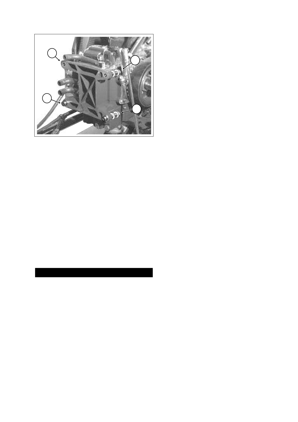
c. Tighten the four transmission housing to crankcase
SIDE
bolts to 15 ft-lbs (20.3 Nm) in the sequence shown
in Figure 3-17.
NOTE
For best results, use Open End Crowfoot (Snap-On FC018)
on upper left and upper right transmission housing to
3
crankcase bolts.
1
d. Following the same sequence, final tighten the four
transmission housing to crankcase bolts to 30-35 ft-
lbs (40.7-47.5 Nm).
e. Tighten the two crankcase to front engine mounting
bracket bolts to 33-38 ft-lbs (44.8-51.5 Nm).
Figure 3-17. Transmission Housing to Crankcase
Torque Sequence
28.
Install horn, top engine mounting bracket and stabilizer
link as an assembly. Proceed as follows:
a. Moving to right side of motorcycle, turn hex head
bolt to secure stabilizer link to frame weldment.
h. Tighten allen head socket screws in fixed holes of
Tighten bolt to 18-22 ft-lbs (24-30 Nm).
flange adapters to 96-144 in-lbs (10.9-16.3 Nm).
b. Install elbow terminals onto spade contacts at back
21.
Cover rocker covers of front and rear cylinders with foam
of horn. Capture wire harness conduit in J-clamp.
padding or bubble pack.
c. Standing on left side of motorcycle, install two hex
22.
Cover lower frame tubes (both left and right side) with
head bolts (with flat washers) to secure top engine
foam padding or bubble pack. Split loom conduit or a half
mounting bracket to front and rear cylinder heads.
shell of PVC tubing will also produce good results. Pro-
Alternately tighten bolts to 35-40 ft-lbs (48-54 Nm).
tection is necessary to prevent nicks or paint damage to
29.
Lower and remove jack under oil pan.
left frame tube and chafing, cutting or kinking of the
brake line, wire cables and conduit at the top of the right
30.
Uncoil main harness conduit and allow to hang below
frame tube.
lower frame tube at front of motorcycle.
23.
Wrap rear master cylinder reservoir with foam padding
31.
Install oil pressure switch/sender and CKP sensor as fol-
or bubble pack.
lows:
a. Start oil pressure switch/sender into crankcase bore
24.
Remove engine from BENCH STAND (HD-42310) or
at the front right side of the crankcase. On FLHR/C/
ROLLING STAND (HD-43646A) and set on floor on right
S models, use a 15/16 inch Open End Crow Foot
side of chassis.
(Snap-On FC30B) to tighten oil pressure switch to
96-120 in-lbs (11-14 Nm). On FLHX, FLHT/C/U
1CAUTION
and FLTR models, use 1-1/16 inch Open End Crow
Foot
(Snap-On FC34A) to tighten oil pressure
The engine weighs approximately 165 pounds (74.8 kg).
sender to same torque.
Use a suitable lifting device, if necessary. Exercise cau-
b. On FLHR/C/S models, install elbow on post of oil
tion to avoid personal injury.
pressure switch. On FLHX, FLHT/C/U and FLTR
25. Raise engine and install in chassis from right side of
models, install Delphi connector to oil pressure
motorcycle setting front of crankcase onto front engine
sender .
mounting bracket. Engine must be set forward far
c. Install new O-ring in groove on crank position sen-
enough to clear two ring dowels in lower flange of trans-
sor body. Apply a very thin film of clean H-D 20W50
mission housing. Exercise caution to avoid contact with
engine oil to O-ring before installation.
rear brake master cylinder reservoir and brake line, wire
d. Push sensor into bore aligning hole in sensor mount
cables and conduit at top of lower right frame tube.
with hole in spot face. Install allen head socket
26. Move engine rearward to fully engage two ring dowels in
screw (1/4 x 1 inch) and tighten to 90-120 in-lbs
lower flange of transmission housing.
(10.2-13.6 Nm).
2006 Touring: Engine
3-25
HOME
d. Install spark plug cable to rear cylinder onto right
9442
side coil tower. Verify that spark plug cable is cap-
tured in two single-sided cable clips at bottom left
side of frame backbone. Install new cable clips on T-
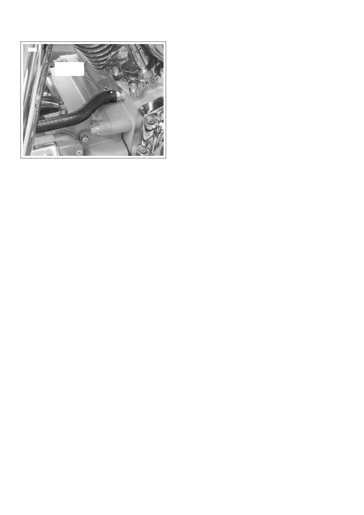
Alignment
studs if damaged or missing.
Dot
37.
If equipped with cruise control, slide groove in cruise
cable end fitting over cap of wheel pin. Push on end fit-
ting until it snaps in place. Using slot, slip cruise cable
housing into cable guide in throttle cable bracket. Install
new E-clip on sleeve at end of cruise cable housing.
38.
Route idle and throttle control cables through J-clamp
fastened to right side of frame backbone.
39.
Install idle and throttle control cables as follows:
Carbureted: Install sleeve on throttle cable housing into
shorter cable guide in throttle cable bracket. Drawing
throttle cable downward, fit barrel end into lower out-
Figure 3-18. Install Breather Hose
board hole in throttle wheel. Install sleeve and spring on
(Hose Clamp Not Shown for Illustration Purposes)
idle cable housing into longer cable guide inserting bar-
rel end into upper inboard hole in throttle wheel.
Induction Module: Install sleeve on throttle cable hous-
e. Mate pin and socket halves of CKP sensor connec-
tor [79], 2-place Deutsch.
ing into shorter cable guide at top of throttle cable
bracket. Drawing throttle cable downward, fit barrel end
32. Install voltage regulator. See Section
8.9 VOLTAGE
into lower hole in throttle wheel. Install sleeve and spring
REGULATOR, INSTALLATION.
on idle cable housing into longer cable guide at bottom
of throttle cable bracket inserting barrel end into upper
33. Slide new clamp onto free end of breather hose behind
hole in throttle wheel.
rear lifter cover. Install hose onto crankcase fitting.
Crimp clamp using HOSE CLAMP PLIERS (HD-97087-
40.
Tighten cables as necessary to keep barrel ends from
65B).
dislodging. Verify that cables are seated in channel of
NOTE
throttle wheel. Verify operation by turning throttle grip
If installing new breather hose or if hose was completely
and observing cable action.
removed, be sure that end with white alignment dot is con-
nected to crankcase fitting and that dot is topside after instal-
41.
Install connections to carburetor or induction module.
Standing on left side of motorcycle, proceed as follows:
lation of hose. See Figure 3-18. Improper orientation can
result in chaffing of the transmission top cover.
Carbureted:
34. Slide new clamps onto free ends of oil hoses. Install
a. Moving to left side of motorcycle, install MAP sensor
hoses onto crankcase fittings. Crimp clamps.
connector [80] at top of intake manifold.
35. Install two allen head socket screws to secure oil hose
cover to transmission and engine housings. Longer
b. Slide threaded portion of enrichener cable into slot
screw goes to engine housing. Alternately tighten
of mounting bracket. Flat on threads must face rear
of motorcycle for script on enrichener knob to be
screws to 84-108 in-lbs (10-12 Nm).
right side up. With the external tooth lockwasher
36. Install ignition coil and spark plug cables as follows:
and hex nut positioned on the inboard side of the
a. With the coil towers facing rear of motorcycle, hold
mounting bracket, tighten hex nut to 20-35 in-lbs
ignition coil and bracket at bottom of frame back-
(2.3-4.0 Nm).
bone. Pull sides of bracket outward and install on
Fuel Injected:
bosses of front fuel tank mount. See Figure 3-11.
b. Connect ignition coil connector [83] to left side of
a. Install rear fuel injector connector [85] and front fuel
ignition coil.
injector connector [84].
c. Install spark plug cable to front cylinder onto left
b. Install MAP sensor connector [80] and IAC connec-
side coil tower. Verify that spark plug cable is cap-
tor [87].
tured in double-sided cable clip at bottom left side of
frame backbone. Install new cable clip on T-stud if
c. Install IAT sensor connector [89] and TP sensor
damaged or missing.
connector [88].
3-26
2006 Touring: Engine