Harley Davidson 2008 Touring Models. Service Manual - page 12
 

  Главная      Harley Davidson     Harley Davidson 2008 Touring Models. Service Manual


Search            copyright infringement  


Content      ..     10      11      12      13     ..


Harley Davidson 2008 Touring Models. Service Manual - page 12


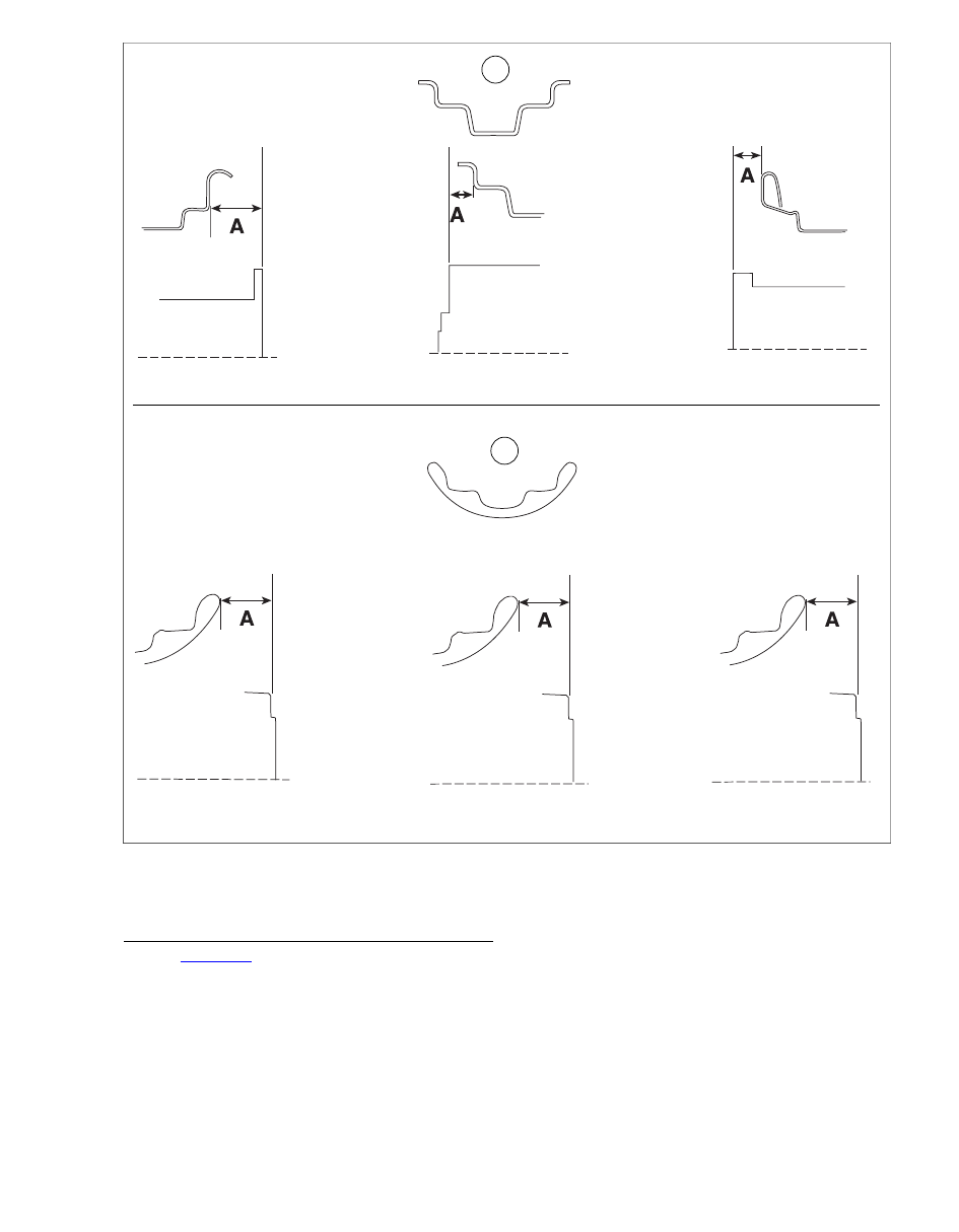
1

2

17"

17"

19"

21"

19"

21"

sm03331

1.

Steel rim

2.

Chrome aluminum profile rim

Figure 2-32. Laced Wheel Hub Offset Dimensions

RADIAL TRUING

1.

See 

Figure 2-33

. Adjust truing stand gauge to the rim's

tire bead seat as shown. The rim should be trued within  
0.030 in. (0.76 mm).

NOTES

Tighten or loosen spoke one flat at a time and recheck
measurement.

Always loosen the appropriate spokes before tightening
the other two. Reversing this procedure will cause the rim
to become out-of-round.

2.

Spin the rim slowly.

a.

If the rim contacts the gauge on or near a marked
group of spokes, loosen the spokes in the marked
group on the opposite side of the rim. Now tighten
the spokes in the group where the rim makes contact.
Loosen and tighten spokes an equal number of turns.

b.

If the rim contacts the gauge between two marked
groups, loosen the spokes in both opposite groups
and tighten the spoke groups on the side of the rim
that makes contact.

2008 Touring Service:  Chassis  2-25

3.

When the wheel is centered and trued, start at the valve
hole and tighten the rest of the spoke nipples one turn at
a time until they are snug.

4.

Seat each spoke head in the hub flange using a flat nose
punch and mallet. Then check wheel trueness again and
tighten the nipples accordingly.

Spokes that are too tight can draw nipples through the rim
or distort hub flanges. Spokes that are too loose can
continue to loosen when put in service. Either condition
can adversely affect stability and handling, which could
result in death or serious injury. (00286a)

5.

Verify spokes are tightened to specification listed in

Table 2-12

.

6.

File or grind off ends of spokes protruding through nipples
to prevent puncturing tube when tire is mounted.

NOTE

After installation of front wheel, visually check the relationship
of the front wheel to the fork fender bosses. The front wheel
should be approximately centered between the bosses.

sm02464

Figure 2-33. Truing Rim Radially

Table 2-12. Spoke Nipple Torque Specification

MINIMUM TORQUE

RIM TYPE

55 in-lbs (6.2 Nm)

All

2-26  2008 Touring Service:  Chassis

2.10

CHECKING CAST WHEEL RUNOUT

GENERAL

The die-cast wheels should be checked for lateral and radial
runout before installing a new tire or tube.

LATERAL RUNOUT

See 

Figure 2-34

. Install arbor in the wheel hub and place wheel

in the truing stand. To check rim lateral runout, place a gauge
rod or dial indicator near the rim bead. If lateral runout exceeds

0.030 in. (0.76 mm), replace the wheel.

sm02465

Figure 2-34. Checking Lateral Runout

RADIAL RUNOUT

TOOL NAME

PART NUMBER

WHEEL TRUING AND BALANCING
STAND

HD-99500-80

See 

Figure 2-35

. Using WHEEL TRUING AND BALANCING

STAND (Part No. HD-99500-80), check for radial runout as
shown. Replace the wheel if runout exceeds  0.030 in. (0.76
mm).

3

1

2

sm03726

1.

Wheel truing and balancing stand

2.

Radial runout

3.

Gauge rod

Figure 2-35. Checking Cast Wheel Radial Runout

2008 Touring Service:  Chassis  2-27

2.11

VEHICLE ALIGNMENT

METHOD A

TOOL NAME

PART NUMBER

VEHICLE ALIGNMENT TOOL

HD-46247A

Check vehicle alignment according to following proced-
ures. Incorrect alignment can adversely affect stability and
handling, which could result in death or serious injury.
(00287a)

NOTE

Use this procedure to realign the powertrain to the frame
whenever major disassembly or engine replacement occurs.
For acceptable results, a careful inspection should be per-
formed (wheel and tire runout, laced wheel offset, rubber mount
condition, etc.) to ensure that it is conducted with serviceable
components. See 

2.11 VEHICLE ALIGNMENT, Inspection

 for

more information.

1.

Place the motorcycle on a hydraulic center stand or place
blocking under the frame to support the vehicle and lift the
rear wheel off the ground. Be sure the motorcycle is posi-
tioned as level as possible.

2.

Remove socket screw with lockwasher to remove left
passenger footboard from rear swingarm bracket. Tighten
both rear swingarm bracket bolts to 34-42 ft-lbs (46-57
Nm). Repeat step on right side of motorcycle.

3.

Remove the decorative chrome plug from both rear
swingarm brackets. While holding the left side pivot shaft
locknut, tighten the right side locknut to 40-45 ft-lbs (54-
61 Nm). Then hold the right side pivot shaft locknut and
tighten the left side locknut to 40-45 ft-lbs (54-61 Nm).

4.

Verify that belt deflection is within specification and that
adjuster cams are tight against rear swingarm weld nubs.
Holding weld nut on left side of axle, tighten cone nut on
right side to 95-105 ft-lbs (128.8-142.4 Nm).

5.

Remove seat. See 

2.26 SEAT

.

6.

Top Engine Mount:

a.

Tighten the two top engine mounting bracket to front
cylinder head bolts to 35-40 ft-lbs (48-54 Nm).

b.

Tighten the top stabilizer link eyelet to frame weldment
bolt to 18-22 ft-lbs (24-30 Nm).

c.

Loosen both top stabilizer link jam nuts.

d.

Remove the top stabilizer link eyelet to top engine
mounting bracket bolt.

sm02895

Figure 2-36. Vehicle Alignment Tool (HD-46247A)

3

2

1

sm02896

1.

Alignment fixture

2.

Pilot

3.

Alignment screw

Figure 2-37. Install Vehicle Alignment Tool (Left Side)

7.

Front Engine Mount:

a.

Remove flange locknuts from studs on lower frame
crossmember. Remove voltage regulator from studs
and allow to hang by cables at front of motorcycle.

b.

Tighten two engine to front engine mounting bracket
bolts to 36-40 ft-lbs (49-54 Nm). See (4) of

Figure 2-38

.

c.

Tighten front stabilizer link eyelet to front engine
mounting bracket bolt to 18-22 ft-lbs (24-30 Nm). See
(2) of 

Figure 2-38

.

d.

Loosen both front stabilizer link jam nuts. See (3) of

Figure 2-38

.

e.

Remove front stabilizer link eyelet to frame weldment
bolt. See (1) of 

Figure 2-38

.

f.

Remove the front engine mounting bracket to rubber
mount bolt (with large and small flat washers and hex
nut). See (5) of 

Figure 2-38

.

2-28  2008 Touring Service:  Chassis

8.

Obtain the VEHICLE ALIGNMENT TOOL (Part No. HD-
46247A) and proceed as follows:

a.

Install alignment screws and pilots in appropriate
alignment fixtures. See 

Figure 2-36

.

NOTE

Be sure to use the alignment fixtures for 2007-08 model
motorcycles, Part No's. HD-46247-7 (Left Side) and HD-
46247-8 (Right Side).

b.

Back off alignment screws and pilots so that no con-
tact is made with pivot shaft during initial installation.

c.

Position alignment fixture so that pilot begins to
engage hole in rear swingarm bracket and then start
5/16 inch allen head screw (with flat washer) into
lower hole of passenger footboard mount. Leave fix-
ture loosely installed. Repeat step on other side of
motorcycle.

NOTE

Alignment fixtures are stamped L(eft) and R(ight) for easy
identification. Reliefs allow the right side fixture to be
installed without removing the hex screws to the brake
hose and exhaust valve actuator cable (HDI) P-clamps.

d.

Holding alignment fixture tight against rear swingarm
bracket, use knurling to rotate pilot until it bottoms in
rear swingarm bracket. Without disturbing setting of
pilot, tighten allen head screw to passenger footboard
mount to  18-22 ft-lb (24-30 Nm). Repeat step on
other side of motorcycle.

e.

Hand turn alignment screw until it bottoms against
end of pivot shaft. Repeat step on other side of
motorcycle.

f.

Tighten alignment screw to  60-80 in-lbs (6.8-9.0
Nm). Repeat step on other side of motorcycle. See

Figure 2-37

.

5

4

2

1

3

6

sm04678

4.

1.

Engine to engine mounting bracket

Stabilizer link eyelet to frame weldment

2.

5.

Stabilizer link eyelet to engine mounting bracket

Engine mounting bracket to rubber mount

6.

3.

Rubber mount to frame crossmember

Stabilizer link jam nuts

Figure 2-38. Front Engine Mount

9.

Adjust each stabilizer link as follows:

a.

Install bolts removed under steps 6(d) and 7(e), and
using the center hex to maintain equal thread
engagement at both eyelets, adjust stabilizer links so
that bolts thread in without any stress or engine
movement.

b.

Alternately tighten bolts to 18-22 ft-lbs (24-30 Nm).

c.

Holding the stabilizer link adjuster and mounting
eyelets to prevent movement or binding, tighten jam
nuts on top and front stabilizer links.

10. Remove vehicle alignment tool from rear swingarm

brackets.

11. Snap the chrome plugs back into the rear swingarm

brackets.

12. Install socket screw with lockwasher to fasten passenger

footboard to rear swingarm bracket. Tighten screw to 30-
35 ft-lbs (40.7-47.5 Nm). Repeat step on other side of
motorcycle.

2008 Touring Service:  Chassis  2-29

NOTE

If removed or replaced, be sure front rubber mount is installed
with the flat plate topside and the larger OD at the bottom. See

Figure 2-39

.

13. Verify that front rubber mount is centered under the front

engine mounting bracket bolt hole and is free of binding.
If centering or relaxation of the rubber mount is required,
proceed as follows:

a.

Loosen the two front rubber mount to frame cross-
member bolts. See (6) of 

Figure 2-38

.

b.

Push on front rubber mount to center it under the bolt
hole. Bounce or wiggle the engine if necessary to
unload the front rubber mount and prevent binding.

14. If the front rubber mount passes inspection, proceed as

follows:

a.

Tighten the two front rubber mount to frame cross-
member bolts to 15-20 ft-lbs (20-27 Nm). See (6) of

Figure 2-38

.

b.

Install front engine mounting bracket to rubber mount
bolt (with large and small flat washers and hex nut)
and tighten to 15-20 ft-lbs (20-27 Nm). See (5) of

Figure 2-38

.

15. Slide voltage regulator over studs on lower frame cross-

member. Install flange locknuts on studs and tighten to
70-100 in-lbs (7.9-11.3 Nm).

sm02897

Figure 2-39. Front Rubber Mount Orientation

16. Verify minimum clearance between the powertrain and

the following components:

a.

Inner Primary Chaincase to Passenger Footboard
Bracket: 0.190 in. (4.8 mm).

b.

Inner Primary Chaincase to Frame (at Engine Crank)

0.190 in. (4.8 mm).

c.

Horn Bracket to Fuel Tank: 0.375 in. (9.5 mm).

d.

Top Engine Mounting Bracket to Frame: 0.190 in. (4.8
mm).

e.

Front Rocker Cover to Fuel Tank: 0.375 in. (9.5 mm).

f.

Rear Rocker Cover to Fuel Tank: 0.375 in. (9.5 mm).

g.

Rear Rocker Cover to Frame: 0.375 in. (9.5 mm).

h.

Perform the procedure under Method B to
troubleshoot clearance problems and to identify
offending component(s).

17. Install seat. See 

2.26 SEAT

.

18. Test ride the motorcycle.

NOTE

Vehicle leads that require more than 2-lbs pull to correct need
further diagnosis. Perform the procedure under 

2.11 VEHICLE

ALIGNMENT, Method B

.

METHOD B

TOOL NAME

PART NUMBER

VEHICLE ALIGNMENT TOOL

HD-46247A

Check vehicle alignment according to following proced-
ures. Incorrect alignment can adversely affect stability and
handling, which could result in death or serious injury.
(00287a)

NOTE

Use this procedure to determine the cause of vehicle misalign-
ment and to locate clearance problems, or as an alternative to
use of the VEHICLE ALIGNMENT TOOL (Part No. HD-46247A)
described under Method A. For acceptable results, a careful
inspection should be performed (wheel and tire runout, laced
wheel offset, rubber mount condition, etc.) to ensure that it is
conducted with serviceable components. See 

2.11 VEHICLE

ALIGNMENT, Inspection

 for more information.

1.

Place the motorcycle on a hydraulic center stand or place
blocking under the frame to support the vehicle and lift the
rear wheel off the ground. Be sure the motorcycle is posi-
tioned as level as possible.

2.

Remove socket screw with lockwasher to remove left
passenger footboard from rear swingarm bracket. Tighten
both rear swingarm bracket bolts to 34-42 ft-lbs (46-57
Nm). Repeat step on right side of motorcycle.

3.

Remove the decorative chrome plug from both rear
swingarm brackets. While holding the left side pivot shaft
locknut, tighten the right side locknut to 40-45 ft-lbs (54-
61 Nm). Then hold the right side pivot shaft locknut and
tighten the left side locknut to 40-45 ft-lbs (54-61 Nm).

4.

Verify that belt deflection is within specification and that
adjuster cams are tight against rear swingarm weld nubs.
Holding weld nut on left side of axle, tighten cone nut on
right side to 95-105 ft-lbs (128.8-142.4 Nm).

5.

Remove seat. See 

2.26 SEAT

.

6.

Top Engine Mount:

a.

Tighten the two top engine mounting bracket to front
cylinder head bolts to 35-40 ft-lbs (48-54 Nm).

b.

Tighten the top stabilizer link eyelet to frame weldment
bolt to 18-22 ft-lbs (24-30 Nm).

c.

Loosen both top stabilizer link jam nuts.

d.

Remove the top stabilizer link eyelet to top engine
mounting bracket bolt.

2-30  2008 Touring Service:  Chassis

7.

Front Engine Mount:

a.

Remove flange locknuts from studs on lower frame
crossmember. Remove voltage regulator from studs
and allow to hang by cables at front of motorcycle.

b.

Tighten two engine to front engine mounting bracket
bolts to 36-40 ft-lbs (49-54 Nm). See (4) of

Figure 2-38

.

c.

Tighten front stabilizer link eyelet to frame weldment
bolt to 18-22 ft-lbs (24-30 Nm). See (1) of 

Figure 2-38

.

d.

Tighten front stabilizer link eyelet to front engine
mounting bracket bolt to 18-22 ft-lbs (24-30 Nm). See
(2) of 

Figure 2-38

.

e.

Remove the front engine mounting bracket to rubber
mount bolt (with large and small flat washers and hex
nut). See (5) of 

Figure 2-38

.

NOTE

If the front tire is wider than the rear, then the alignment bars
must either be shimmed out equally at the points of contact on
the rear tire, notched at the front to clear the front tire, or
attached to the front tire with all measurements performed at
the rear. For explanatory purposes, the following procedure
assumes the alignment bars are secured to the rear tire.

8.

To verify alignment, install alignment bars or other suitable
device on both the left and right side of motorcycle. Pro-
ceed as follows:

a.

Place a set of straightedges on both the left and right
sides of the motorcycle alongside the front and rear
tires.

b.

Verify that both alignment bars firmly contact the rear
wheel at two points. Use clamp or bungee cords to
hold the bars in place. Tension should be equal to
avoid spreading or pinching the bars.

c.

Verify that the bars are straight by matching the width
measurements at both ends.

d.

Straighten the front end and verify that the measure-
ments from the front wheel to the bar on one side of
the motorcycle are equal at two points, both fore and
aft.

e.

Measure the front wheel to the bar on the other side
of the motorcycle, both fore and aft, and compare the
results to the measurements obtained under step
8(d). Measurements from left to right should be equal
+/-  0.030 in. (0.76 mm).

f.

Loosen jam nuts, and using the center hex, adjust
the front stabilizer link as required to obtain equal
measurements at all four points +/-  0.030 in. (0.76
mm). See 

Figure 2-40

.

NOTE

After each adjustment, unload any binding of the front
rubber mount and verify that the alignment bars and front
wheel are still correctly positioned.

g.

Holding the front stabilizer link adjuster and mounting
eyelets to prevent movement or binding, tighten both
jam nuts.

9.

Verify that front rubber mount is centered under the front
engine mounting bracket bolt hole and is free of binding.

If centering or relaxation of the rubber mount is required,
proceed as follows:

a.

Loosen the two front rubber mount to frame cross-
member bolts. See (6) of 

Figure 2-38

.

b.

Push on front rubber mount to center it under the bolt
hole. Bounce or wiggle the engine if necessary to
unload the front rubber mount and prevent binding.

10. If the front rubber mount passes inspection, proceed as

follows:

a.

Tighten the two front rubber mount to frame cross-
member bolts to 15-20 ft-lbs (20-27 Nm). See (6) of

Figure 2-38

.

b.

Install front engine mounting bracket to rubber mount
bolt (with large and small flat washers and hex nut)
and tighten to 15-20 ft-lbs (20-27 Nm). See (5) of

Figure 2-38

.

1

2

sm03572

1.

Chassis

2.

Powertrain

Figure 2-40. Horizontally Misaligned

11. Slide voltage regulator over studs on lower frame cross-

member. Install flange locknuts on studs and tighten to
70-100 in-lbs (7.9-11.3 Nm).

2008 Touring Service:  Chassis  2-31

12. Adjust the top stabilizer link as follows:

a.

Using the center hex to maintain equal thread
engagement at both eyelets, adjust stabilizer link so
that bolt removed under step 6(d) threads in without
any stress or engine movement.

b.

Tighten the stabilizer link eyelet to top engine
mounting bracket bolt to 18-22 ft-lbs (24-30 Nm).

c.

Holding the top stabilizer link adjuster and mounting
eyelets to prevent movement or binding, tighten both
jam nuts.

13. Lower motorcycle to floor and remove hydraulic center

stand or blocking.

1

2

sm03573

1.

Chassis

2.

Powertrain

Figure 2-41. Vertically Misaligned

14. After verifying that the motorcycle is level, check vertical

alignment placing an inclinometer on both front and rear
brake discs. Front and rear lean angles should be equal

+/- 1/2 degree. See 

Figure 2-38

. If vertical alignment

exceeds specification, proceed as follows:

a.

Loosen the top stabilizer link eyelet to top engine
mounting bracket bolt. Verify that bolt is unloaded and
threads freely in and out of the mounting bracket hole.
If necessary, loosen jam nuts and adjust stabilizer
link to a achieve a free state. Tighten bolt to 18-22 ft-
lbs (24-30 Nm)and then tighten jam nuts before
rechecking vertical alignment.

b.

Look for components that are worn, damaged or out
of specification. See 

2.11 VEHICLE ALIGNMENT,

Inspection

.

15. Remove the alignment bars from both the left and right

side of the motorcycle.

16. Snap the chrome plugs back into the rear swingarm

brackets.

17. Install socket screw with lockwasher to fasten passenger

footboard to rear swingarm bracket. Tighten screw to 30-
35 ft-lbs (40.7-47.5 Nm). Repeat step on other side of
motorcycle.

18. Verify minimum clearance between the powertrain and

the following components:

a.

Inner Primary Chaincase to Passenger Footboard
Bracket: 0.190 in. (4.8 mm).

b.

Inner Primary Chaincase to Frame (at Engine Crank)

0.190 in. (4.8 mm).

c.

Horn Bracket to Fuel Tank: 0.375 in. (9.5 mm).

d.

Top Engine Mounting Bracket to Frame: 0.190 in. (4.8
mm).

e.

Front Rocker Cover to Fuel Tank: 0.375 in. (9.5 mm).

f.

Rear Rocker Cover to Fuel Tank: 0.375 in. (9.5 mm).

g.

Rear Rocker Cover to Frame: 0.375 in. (9.5 mm).

19. Install seat. See 

2.26 SEAT

.

20. Test ride the motorcycle.

NOTE

Vehicle leads that require more than 2-lbs pull to correct need
further diagnosis. See 

2.11 VEHICLE ALIGNMENT, Inspection

.

INSPECTION

See 

1.2 MAINTENANCE SCHEDULE

 for the required service

interval. Perform inspection sooner if there are abnormal
handling characteristics/vibrations or any sag in the powertrain.

Front Rubber Mount

1.

Verify condition and torque of the mounting hardware.
Visually inspect for wear, damage or improper installation.
Replace hardware as necessary.

2.

Examine carefully at the bottom of the motorcycle paying
special attention to the area between the large flat metal
washer and the bracket on the frame. There should be a
gap between the mounting plate and the cushion portion
of the rubber mount.

3.

Replace the rubber mount if there are any signs of cracking
or shearing.

2-32  2008 Touring Service:  Chassis

Rear Swingarm Mounts

1.

Verify condition and torque of the mounting hardware.
Visually inspect for wear, damage or improper installation.
Replace hardware as necessary.

2.

Examine rubber mount to be sure there is no twisting or
binding at the parting line.

Engine Stabilizer Links

1.

Verify condition and torque of the mounting hardware.
Visually inspect for wear, damage or improper installation.
Replace hardware as necessary.

2.

Using flats machined into the stabilizer eyelet, gently rock
the link and check for separation of the molded-in sleeve.
Replace as necessary.

Wear in the link also can be measured with a dial indicator
by hand compressing and then releasing the link. Replace
any link that exceeds  0.025 in. (0.64 mm) of play or wear.

2008 Touring Service:  Chassis  2-33

2.12

FRONT BRAKE MASTER CYLINDER

GENERAL

Do not allow dirt or debris to enter the master cylinder
reservoir. Dirt or debris in the reservoir can cause improper
operation and equipment damage. (00205c)

Direct contact of D.O.T. 4 brake fluid with eyes can cause
irritation. Avoid eye contact. In case of eye contact flush
with large amounts of water and get medical attention.
Swallowing large amounts of D.O.T. 4 brake fluid can cause
digestive discomfort. If swallowed, obtain medical atten-
tion. Use in well ventilated area. KEEP OUT OF REACH OF
CHILDREN. (00240a)

D.O.T. 4 brake fluid will damage painted and body panel
surfaces it comes in contact with. Always use caution and
protect surfaces from spills whenever brake work is per-
formed. Failure to comply can result in cosmetic damage.
(00239b)

NOTE

Immediately wipe up any brake fluid spillage with a clean, dry,
soft cloth. Follow up by thoroughly wiping affected area with a
clean, damp, soft cloth (small spills) or washing with a large
quantity of soapy water (large spills).

REMOVAL AND DISASSEMBLY

Removal

1.

Resting motorcycle on jiffy stand, turn front wheel toward
the left fork stop until the master cylinder reservoir is level.

2.

To prevent dirt and other contaminants from entering the
master cylinder reservoir, thoroughly clean the cover
before removal.

3.

Remove two screws to release cover from master cylinder
reservoir.

NOTE

Wrap banjo fitting with piece of shop towel to absorb any loss
of brake fluid.

4.

Remove banjo bolt to release brake line from master cyl-
inder reservoir. Hold suitable container under banjo bolt
bore to allow reservoir to drain. Discard copper washers.

5.

Using a clean shop cloth, wipe out any remaining fluid in
the master cylinder reservoir.

Do not remove or install the master cylinder assembly
without first positioning a 5/32-inch (4 mm) thick insert
between the brake lever and lever bracket. Removing or
installing the master cylinder assembly without the insert
in place may result in damage to the rubber boot and
plunger on the front stoplight switch. (00324a)

6.

Place cardboard insert between brake lever and lever
bracket. Use the eyelet of a small cable strap if the card-
board insert is not available.

7.

Remove two screws to release handlebar clamp from
master cylinder reservoir. Remove clamp and master cyl-
inder reservoir/brake lever assembly from handlebar. See

Figure 2-42

.

8.

Remove cardboard insert between brake lever and lever
bracket.

9.

Remove retaining ring from pivot pin groove at bottom of
brake lever bracket. Discard retaining ring.

10. Remove pivot pin and brake lever from brake lever bracket.

1

4

5

3

2

sm05016

1.

Tab

2.

Groove

3.

Switch housing assembly

4.

Brake lever bracket

5.

Cardboard insert

Figure 2-42. Remove Master Cylinder/Brake Lever

Assembly

Disassembly

NOTE

Exercise care to avoid scratching or nicking banjo sealing
surface during handling. Damage to the sealing surface
requires replacement of the master cylinder reservoir.

1.

Pull dust boot (with pushrod) from piston bore. Remove
dust boot from pushrod. See 

Figure 2-43

.

2.

Remove retaining ring from groove in piston bore. As the
piston assembly is spring loaded, hold parts together as
retaining ring is removed.

3.

Pull piston assembly from piston bore.

2-34  2008 Touring Service:  Chassis

2

3

4

19

1

8

7

9

18

17

16

15

14

13

12

11

10

5

6

sm05012

11.

1.

Dust boot

Master cylinder reservoir

2.

12.

Cover screw (2)

Retaining ring

13.

3.

Secondary seal

Cover

4.

14.

Gasket

Piston

15.

5.

Flat washer

Clamp screw (2)

6.

16.

Handlebar clamp

Primary seal

17.

7.

E-clip

Retaining ring

8.

18.

Pivot pin

Spring

19.

9.

Sight glass/O-ring

Brake hand lever

10. Pushrod

Figure 2-43. Front Brake Master Cylinder Assembly

2008 Touring Service:  Chassis  2-35

CLEANING AND INSPECTION

Use denatured alcohol to clean brake system components.
Do not use mineral-based solvents (such as gasoline or
paint thinner), which will deteriorate rubber parts even
after assembly. Deterioration of these components can
cause brake failure, which could result in death or serious
injury. (00291a)

Compressed air can pierce the skin and flying debris from
compressed air could cause serious eye injury. Wear
safety glasses when working with compressed air. Never
use your hand to check for air leaks or to determine air
flow rates. (00061a)

1.

Clean all parts with denatured alcohol. Wipe dry with a
clean, lint free cloth.

2.

Inspect banjo seating surface for scratches or nicks.

3.

Verify that reservoir is completely free of dust, dirt or
residue.

4.

Using a clean air supply, blow out piston bore and other
drilled passages. Do not use a wire or similar instrument.

5.

Inspect piston bore for scratches, nicks, scoring, pitting,
corrosion or other damage.

6.

Inspect retaining ring for wear or distortion. Inspect
retaining ring groove for damage.

7.

Inspect spring for stretching, distortion, kinks, cracks or
broken coils.

8.

Inspect piston seals, dust boot and reservoir cover gasket
for cuts, tears or general deterioration.

ASSEMBLY AND INSTALLATION

Assembly

1.

Lightly lubricate piston bore and OD of piston seals with
D.O.T. 4 brake fluid.

2.

Insert spring end of piston assembly into piston bore.

3.

While pushing on piston to compress spring, install
retaining ring in groove of piston bore (with the flat side
in). Verify that retaining ring is completely seated in groove.

4.

Install dust boot onto pushrod, so that ID on tapered end
engages groove in pushrod.

5.

Install dust boot into piston bore fitting ball end of pushrod
into piston socket. Verify that collar on OD of dust boot is
inboard of lip in piston bore.

Installation

1.

Place dab of G-40M grease (HD Part No. 42820-04) into
pocket of hand lever. See 

Figure 2-44

.

2.

Align hole in brake hand lever with hole in brake lever
bracket. Slide pivot pin through brake lever bracket and
hand lever.

3.

Install new retaining ring in pivot pin groove. Verify that
retaining ring is completely seated in groove.

4.

Place cardboard insert between brake lever and brake
lever bracket. Use the eyelet of an ordinary cable strap if
the cardboard insert is not available.

5.

Position brake lever/master cylinder reservoir assembly
inboard of switch housing assembly engaging tab on lower
switch housing in groove at top of brake lever bracket.

6.

Align holes in handlebar clamp with those in master cyl-
inder reservoir and start two screws (with flat washers).
Position for rider comfort. Beginning with the top screw,
tighten screws to 72-80 in-lbs (8-9 Nm).

7.

Start banjo bolt (with new copper washers) to secure brake
line to master cylinder reservoir.

8.

Tighten banjo bolt to master cylinder to 13-15 ft-lbs (17.6-
20.3 Nm).

9.

Fill and bleed brake system. See 

1.14 BLEEDING

BRAKES

.

2

1

sm05015

1.

Pushrod

2.

Lever pocket

Figure 2-44. Apply Grease to Lever Pocket

FRONT BRAKE LINE

Removal

1.

FLHR/C:

a.

Remove right side headlamp nacelle. See

2.45 HEADLAMP NACELLE: FLHR/C

.

b.

Cut cable strap to release right handlebar switch
conduit and brake hose from right handlebar riser.
See 

Figure 2-45

.

c.

Carefully cut cable strap to release front fender tip
lamp wires from left brake caliper hose. See

Figure 2-46

.

2-36  2008 Touring Service:  Chassis

2.

FLHX, FLHT/C/U:

a.

Remove outer fairing and fairing cap. See

2.35 UPPER FAIRING AND WINDSHIELD: FLHX,
FLHT/C/U

 and 

2.36 FAIRING CAP: FLHX, FLHT/C/U

,

respectively.

b.

Just outboard of fairing cap opening, cut cable strap
to release right handlebar switch conduit and brake
line from right handlebar.

c.

Carefully cut cable strap to release front fender tip
lamp wires from left brake caliper hose. See

Figure 2-46

.

3.

FLTR:

a.

Remove right side instrument nacelle. See

2.41 INSTRUMENT NACELLE: FLTR

.

b.

If present, remove hex screw to release P-clip from
front right side of upper fork bracket. Remove P-clip
from brake line.

4.

Remove screw at bottom of lower fork bracket to release
front brake line bracket.

5.

Resting motorcycle on jiffy stand, turn front wheel toward
the left fork stop until the master cylinder reservoir is level.

6.

To prevent dirt and other contaminants from entering the
master cylinder reservoir, thoroughly clean the cover
before removal.

7.

Remove two screws to release cover from master cylinder
reservoir.

NOTE

Wrap banjo fittings with pieces of shop towel to absorb any
loss of brake fluid.

8.

Remove banjo bolt to release brake line from master cyl-
inder reservoir. Hold suitable container under banjo bolt
bore to allow reservoir to drain. Discard copper washers.

9.

Using a clean shop cloth, wipe out any remaining fluid in
the master cylinder reservoir.

10. Remove banjo bleeder bolt to disconnect brake line from

left brake caliper. Discard copper washers. Repeat step
to release brake line from right brake caliper.

11. Remove front brake line from motorcycle.

sm03522

Figure 2-45. Capture Brake Hose and Right Handlebar

Riser (FLHR/C)

sm03520

Figure 2-46. Capture Brake Hose and Front Fender Tip

Lamp Wires

Installation

1.

Position the front brake line bracket at the bottom of the
lower fork bracket, so that single brake line runs up along
the front right side of the fork brackets before turning to
follow the bottom of the right handlebar to the master cyl-
inder reservoir.

2.

Align larger hole in front brake line bracket with threaded
boss at bottom of lower fork bracket. Start screw into
threaded boss. Verify that brake lines to the front brake
calipers, as viewed at the rear of the lower fork bracket,
are equal distance from the left and right fork sliders, and
then tighten screw until snug.

3.

Start banjo bolt (with new copper washers) to secure brake
line to master cylinder reservoir.

4.

Start banjo bleeder bolts (with new copper washers) to
secure brake lines to both left and right brake calipers.

5.

Tighten banjo bolt to master cylinder reservoir to 13-15 ft-
lbs (17.6-20.3 Nm).

6.

Tighten banjo bleeder bolts to brake calipers to 17-19 ft-
lbs (23.1-25.8 Nm).

7.

Tighten screw at bottom of lower fork bracket to 120-180
in-lbs (13.6-20.3 Nm).

8.

Fill and bleed brake system. See 

1.14 BLEEDING

BRAKES

.

9.

FLHR/C:

a.

Install new cable strap to secure right handlebar
switch conduit and brake hose to right handlebar riser.
See 

Figure 2-45

.

b.

Install right side headlamp nacelle. See 

2.45 HEAD-

LAMP NACELLE: FLHR/C

.

c.

Install new cable strap to secure front fender tip lamp
wires to left brake caliper hose. See 

Figure 2-46

.

2008 Touring Service:  Chassis  2-37

10. FLHX, FLHT/C/U:

a.

Just outboard of fairing cap opening, install new cable
strap to secure right handlebar switch conduit and
brake line to right handlebar.

b.

Install fairing cap and outer fairing. See 

2.36 FAIRING

CAP: FLHX, FLHT/C/U

 and 

2.35 UPPER FAIRING

AND WINDSHIELD: FLHX, FLHT/C/U

, respectively.

c.

Install new cable strap to secure front fender tip lamp

wires to left brake caliper hose. See 

Figure 2-46

.

11. FLTR:

a.

If present, capture brake line in P-clip. Install hex
screw to fasten P-clip to front right side of upper fork
bracket.

b.

Install right side instrument nacelle. See

2.41 INSTRUMENT NACELLE: FLTR

.

2-38  2008 Touring Service:  Chassis

2.13

FRONT BRAKE CALIPER

REMOVAL

NOTE

If only replacing brake pads, see 

1.15 BRAKE PADS AND

DISCS

.

1.

Remove banjo bleeder bolt to release brake line to caliper.
Discard copper washers.

NOTE

Wrap banjo fitting with piece of shop towel to absorb any loss
of brake fluid.

2.

Left side caliper of ABS equipped motorcycles only:
Release front wheel speed sensor cable from clip as fol-
lows:

a.

Push on lip at rear of clip to disengage from bracket.

b.

Rotate tab (stamped ABS) rearward until clip is per-
pendicular to bracket and remove cable.

3.

Remove two caliper mounting screws (with front wheel
speed sensor cable clip/bracket if left side caliper of ABS
equipped motorcycle). Remove caliper from brake disc.
See 

Figure 2-47

.

1

3

4

2

7

6

5

sm04988

1.

Caliper

2.

Caliper mounting screw

3.

Screen

4.

Retaining clip

5.

Pad pin

6.

Brake pads

7.

Pad spring

Figure 2-47. Front Brake Caliper Assembly

INSTALLATION

1.

If necessary, assemble caliper installing pad spring, brake
pads, pad pin, retaining clip and screen. See 

1.15 BRAKE

PADS AND DISCS

.

2.

Slide caliper onto brake disc, so that holes are aligned
with lugs on fork slider.

3.

Start two mounting screws (with cable clip/bracket if left
side caliper on ABS equipped motorcycle), and alternately
tighten to 28-38 ft-lbs (37.9-51.5 Nm)

4.

Left side caliper of ABS equipped motorcycles only:
Install front wheel speed sensor cable into clip as follows:

a.

Rotate tab (stamped ABS) until clip is perpendicular
to bracket and install cable.

b.

Rotate tab forward until clip is inline with bracket and
then apply pressure to tab until lip engages. Gently
pull on cable to verify that clip is properly installed.

5.

Start banjo bleeder bolt (with new copper washers) to
secure brake line to caliper. Tighten bolt to 17-19 ft-
lbs (23.1-25.8 Nm).

NOTE

When replacing or installing the bleeder valve, remove the o-
ring from the bleeder valve groove or bore and discard. The
o-ring is required only for brake bleeding at the factory.
Although not sold separately, it may be present in certain
assemblies as currently sold. If care is not taken to remove
and discard the o-ring, it may become lodged in the banjo
bleeder bolt bore during bleeder valve installation and prevent
proper torquing or sealing.

6.

Fill and bleed brake system. See 

1.14 BLEEDING

BRAKES

.

2008 Touring Service:  Chassis  2-39

2.14

REAR BRAKE MASTER CYLINDER

GENERAL

Do not allow dirt or debris to enter the master cylinder
reservoir. Dirt or debris in the reservoir can cause improper
operation and equipment damage. (00205c)

Direct contact of D.O.T. 4 brake fluid with eyes can cause
irritation. Avoid eye contact. In case of eye contact flush
with large amounts of water and get medical attention.
Swallowing large amounts of D.O.T. 4 brake fluid can cause
digestive discomfort. If swallowed, obtain medical atten-
tion. Use in well ventilated area. KEEP OUT OF REACH OF
CHILDREN. (00240a)

D.O.T. 4 brake fluid will damage painted and body panel
surfaces it comes in contact with. Always use caution and
protect surfaces from spills whenever brake work is per-
formed. Failure to comply can result in cosmetic damage.
(00239b)

NOTE

Immediately wipe up any brake fluid spillage with a clean, dry,
soft cloth. Follow up by thoroughly wiping affected area with a
clean, damp, soft cloth (small spills) or washing with a large
quantity of soapy water (large spills).

REMOVAL AND DISASSEMBLY

Removal

1.

Remove right fairing lower, if present. See 

2.34 LOWER

FAIRING AND ENGINE GUARD

.

2.

Remove right side rider footboard. See 

2.49 FOOT-

BOARDS AND FOOTRESTS

.

3.

Stand motorcycle upright, so that rear master cylinder
reservoir is level.

4.

To prevent dirt and other contaminants from entering the
master cylinder reservoir, thoroughly clean the cover
before removal.

5.

Remove two screws to release cover from master cylinder
reservoir.

1

6

2

3

5

4

sm05022

4.

1.

Cotter pin

Rear brake pedal

2.

5.

O-ring (2)

Flat washer

6.

3.

Master cylinder reservoir

Clevis pin

Figure 2-48. Rear Master Cylinder/Brake Pedal Assembly

2-40  2008 Touring Service:  Chassis


Content      ..     10      11      12      13     ..