Harley Davidson 2008 Touring Models. Service Manual - page 9
 

  Главная      Harley Davidson     Harley Davidson 2008 Touring Models. Service Manual


Search            copyright infringement  


Content      ..     7      8      9      10     ..


Harley Davidson 2008 Touring Models. Service Manual - page 9


Table 1-11. Antidotes for Battery Acid

TREATMENT

CONTACT

Flush with water.

External

Drink large quantities of milk or water, followed
by milk of magnesia, vegetable oil or beaten
eggs. Get immediate medical attention.

Internal

Flush with water. Get immediate medical
attention.

Eyes

CLEANING AND INSPECTION

1.

Battery top must be clean and dry. Dirt and electrolyte on
top of the battery can cause battery to self-discharge.
Clean battery top with a solution of baking soda (sodium
bicarbonate) and water (5 teaspoons baking soda per
quart or liter of water). When the solution stops bubbling,
rinse off the battery with clean water.

2.

Clean cable connectors and battery terminals using a wire
brush or sandpaper. Remove any oxidation.

3.

Inspect the battery screws, clamps and cables for
breakage, loose connections and corrosion. Clean clamps.

4.

Check the battery posts for melting or damage caused by
overtightening.

5.

Inspect the battery for discoloration, raised top or a warped
or distorted case, which might indicate that the battery has
been frozen, overheated or overcharged.

6.

Inspect the battery case for cracks or leaks.

BATTERY: TOURING MODELS

Disconnection and Removal

1.

Remove seat. See 

2.26 SEAT

.

2.

If present, release tongue on HFSM antenna from groove
at front of top caddy. Move connector and conduit out of
the way.

3.

Remove screw to release clamp on top caddy from frame
crossmember.

4.

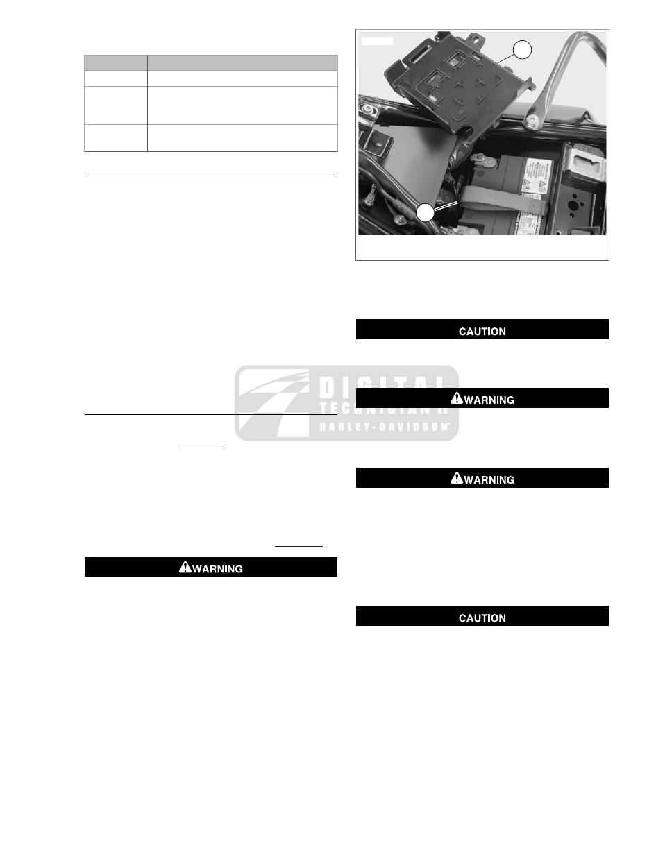
Rotate ECM connector conduit so that top caddy is posi-
tioned above upper right frame tube. See 

Figure 1-32

.

Disconnect negative (-) battery cable first. If positive (+)
cable should contact ground with negative (-) cable con-
nected, the resulting sparks can cause a battery explosion,
which could result in death or serious injury. (00049a)

5.

Unthread bolt and remove battery negative cable (black)
from battery negative (-) terminal.

6.

Unthread bolt and remove battery positive cable (red) from
battery positive (+) terminal.

7.

Unfold lifting strap. Grasp loop at end of lifting strap and
pull up to raise battery. When battery is extracted far
enough to get a good grip, remove the rest of the way by
hand.

1

2

sm04651

1.

Top caddy

2.

Lifting strap

Figure 1-32. Move Top Caddy Aside

Installation and Connection

Connect the cables to the correct battery terminals. Failure
to do so could result in damage to the motorcycle electrical
system. (00215a)

Connect positive (+) battery cable first. If positive (+) cable
should contact ground with negative (-) cable connected,
the resulting sparks can cause a battery explosion, which
could result in death or serious injury. (00068a)

Do not allow positive (+) battery cable to contact ground
with negative (-) cable connected. Resulting sparks can
cause a battery explosion, which could result in death or
serious injury. (00069a)

1.

Run lifting strap rearward first down the center of the bat-
tery tray, then up and across the frame crossmember.

2.

Place the fully charged battery into the battery tray, ter-
minal side forward.

Do not over-tighten bolts on battery terminals. Use
recommended torque values. Over-tightening battery ter-
minal bolts could result in damage to battery terminals.
(00216a)

3.

Insert bolt through battery positive cable (red) into threaded
hole of battery positive (+) terminal. Tighten bolt to 60-96
in-lbs (6.8-10.9 Nm).

4.

Insert bolt through battery negative cable (black) into
threaded hole of battery negative (-) terminal. Tighten bolt
to 60-96 in-lbs (6.8-10.9 Nm).

2008 Touring Service:  Maintenance  1-37

Keep battery clean and lightly coat terminals with petro-
leum jelly to prevent corrosion. Failure to do so could
result in damage to battery terminals. (00217a)

5.

Apply a light coat of petroleum jelly or ELECTRICAL
CONTACT LUBRICANT, Part No. 99861-02 (1 oz tube),
to both battery terminals.

6.

Fold lifting strap forward over top of battery. See

Figure 1-32

.

7.

Rotate ECM connector conduit so that top caddy is posi-
tioned above battery.

8.

Install screw to fasten clamp on top caddy to frame
crossmember. Tighten screw to 15-20 ft-lbs (20-27 Nm).

9.

Routing conduit along inboard side of left upper frame
tube, engage tongue on HFSM antenna in groove at front
of top caddy, if present.

10. Install seat. See 

2.26 SEAT

.

VOLTMETER TEST

Batteries contain sulfuric acid, which could cause severe
burns to eyes and skin. Wear a protective face shield,
rubberized gloves and protective clothing when working
with batteries. KEEP BATTERIES AWAY FROM CHILDREN.
(00063a)

Never remove warning label attached to top of battery.
Failure to read and understand all precautions contained
in warning, could result in death or serious injury. (00064a)

Voltmeter Test

Refer to 

Table 1-12

. The voltmeter test provides a general

indicator of battery condition. Check the voltage of the battery
to verify that it is in a 100% fully charged condition. If the open
circuit (disconnected) voltage reading is below 12.6V, charge
the battery and then recheck the voltage after the battery has
set for one to two hours. If the voltage reading is 12.7V or
above, perform a load test. See the ELECTRICAL DIA-
GNOSTIC MANUAL for the load test procedure.

Table 1-12. Voltmeter Test For Battery Charge Conditions

STATE OF CHARGE

VOLTAGE (OCV)

100%

12.7 V

75%

12.6 V

50%

12.3 V

25%

12.0 V

0%

11.8 V

CHARGING BATTERY

Safety Precautions

Never charge a battery without first reviewing the instructions
for the charger being used. In addition to the manufacturer's
instructions, follow these general safety precautions:

Always wear eye, face and hand protection.

Always charge batteries in a well-ventilated area.

Turn the charger off before connecting the leads to the
battery to avoid dangerous sparks.

Never try to charge a visibly damaged or frozen battery.

Connect the charger leads to the battery; red positive (+)
lead to the positive (+) terminal and black negative (-) lead
to the negative (-) terminal. If the battery is still in the
vehicle, connect the negative lead to the chassis ground.
Be sure that the ignition and all electrical accessories are
turned off.

Make sure that the charger leads to the battery are not
broken, frayed or loose.

If the battery gets hotter than  110° F (43° C) during
charging, discontinue charger and allow the battery to
cool.

Always turn the charger off before removing charger leads
from the battery to avoid dangerous sparks.

Using a Battery Charger

Charge the battery if any of the following conditions exist:

Vehicle lights appear dim.

Electric starter sounds weak.

Battery has not been used for an extended period of time.

Explosive hydrogen gas, which escapes during charging,
could cause death or serious injury. Charge battery in a
well-ventilated area. Keep open flames, electrical sparks
and smoking materials away from battery at all times.
KEEP BATTERIES AWAY FROM CHILDREN. (00065a)

If battery releases an excessive amount of gas during
charging, decrease the charging rate. Overheating can
result in plate distortion, internal shorting, drying out or
damage. (00413b)

1.

Perform a voltmeter test to determine the state of charge.
See the ELECTRICAL DIAGNOSTIC MANUAL. If battery
needs to be charged, proceed to the next step.

NOTE

The figures listed in the table assume that the battery is char-
ging at room temperature. If warmer than room temperature,
use a slightly shorter charging time. If colder, use a slightly
longer charging time.

1-38  2008 Touring Service:  Maintenance

Table 1-13. 28 Amp-Hour Battery Charging Rate/Times

20 AMP

CHARGER

10 AMP

CHARGER

6 AMP

CHARGER

3 AMP

CHARGER

PERCENT

OF CHARGE

READING

(VOLTS)

-

-

-

-

100

12.7

25 minutes

45 minutes

1.25 hours

2.5 hours

75

12.6

50 minutes

1.5 hours

2.5 hours

5 hours

50

12.3

70 minutes

2.25 hours

3.75 hours

7.5 hours

25

12.0

1.5 hours

3 hours

5 hours

10 hours

0

11.8

NOTE

The use of constant current chargers to charge sealed main-
tenance-free batteries is not recommended. Any overcharge
will cause dry-out and premature battery failure. If a constant
current charger is the only type available, do not exceed the
charge times listed above and do not continue charging the
battery if it gets hot. When charging, never exceed 15 volts for
more than 30 minutes.

Unplug or turn OFF battery charger before connecting
charger cables to battery. Connecting cables with charger
ON can cause a spark and battery explosion, which could
result in death or serious injury. (00066a)

Do not reverse the charger connections described in the
following steps or the charging system of the motorcycle
could be damaged. (00214a)

2.

Connect red battery charger lead to the positive (+) ter-
minal of the battery.

3.

Connect black battery charger lead to the negative (-)
terminal of the battery.

NOTE

If the battery is still in the vehicle, connect the negative lead
to the chassis ground. Be sure that the ignition and all electrical
accessories are turned off.

4.

Step away from the battery and turn on the charger. See
the charging instructions in 

Table 1-13

.

Unplug or turn OFF battery charger before disconnecting
charger cables from battery. Disconnecting clamps with
charger ON can cause a spark and battery explosion, which
could result in death or serious injury. (00067a)

5.

After the battery is fully charged, disconnect the black
battery charger lead to the negative (-) terminal of the
battery.

6.

Disconnect the red battery charger lead to the positive (+)
terminal of the battery.

7.

Mark the charging date on the battery.

8.

Perform either a conductance test or load test to determine
the condition of the battery. See the ELECTRICAL DIA-
GNOSTIC MANUAL.

9.

If charging battery because voltmeter test reading was
below 12.6 V, perform voltmeter test. See the ELEC-
TRICAL DIAGNOSTIC MANUAL.

STORAGE

TOOL NAME

PART NUMBER

GLOBAL BATTERY CHARGER

99863-01A

Batteries contain sulfuric acid, which could cause severe
burns to eyes and skin. Wear a protective face shield,
rubberized gloves and protective clothing when working
with batteries. KEEP BATTERIES AWAY FROM CHILDREN.
(00063a)

Do not allow battery to completely discharge. The electro-
lyte in a discharged battery will freeze. The more dis-
charged a battery is, the more easily it can freeze and crack
the battery case. (00218a)

If the motorcycle is to be stored with the security system armed,
connect a GLOBAL BATTERY CHARGER (Part No. 99863-
01A) to maintain battery charge.

If the motorcycle is to be stored with the battery installed, a
GLOBAL BATTERY CHARGER unavailable, and with the
security system not armed, unplug the maxi-fuse.

If the motorcycle will not be operated for several months, such
as during the winter season, remove the battery from the
motorcycle and fully charge.

See 

Figure 1-33

. Self-discharge is a normal condition and

occurs continuously at a rate that depends on the ambient
temperature and the battery's state of charge. Batteries dis-
charge at a faster rate at higher ambient temperatures. To
reduce the self-discharge rate, store battery in a cool (not
freezing), dry place.

Charge the battery every month if stored at temperatures below

60° F (16° C). Charge the battery more frequently if stored in

a warm area above  60° F (16° C).

2008 Touring Service:  Maintenance  1-39

NOTES

The GLOBAL BATTERY CHARGER (Part No. 99863-01A)
may be used to maintain battery charge for extended
periods of time without risk of overcharging or boiling.

When returning a battery to service after storage, see
ELECTRICAL DIAGNOSTIC MANUAL.

3

6

9

12

15

50 %

75 %

100 %

0

¡

¡

105° F (40.5° C)

77° F (25° C)

1

2

sm02838

1.

Capacity

2.

Months of stand

Figure 1-33. Battery Self-Discharge Rate

1-40  2008 Touring Service:  Maintenance

1.17

SUSPENSION ADJUSTMENTS

GENERAL

TOOL NAME

PART NUMBER

AIR SUSPENSION PUMP AND
GAUGE

HD-34633A

Adjust the rear air suspension pressure by adding or removing
air from the air valve located just below the frame cover on the
left side of the motorcycle. See 

Figure 1-34

. Always adjust

pressures with the motorcycle on the jiffy stand.

Air pressure may be varied to suit load conditions, riding style
and personal comfort. Less initial pressure does not necessarily
result in a softer ride. Refer to the tables below for the recom-
mended air suspension pressures.

Do not exceed the motorcycle's Gross Vehicle Weight
Rating (GVWR) or Gross Axle Weight Rating (GAWR).
Exceeding these weight ratings can affect stability and
handling, which could result in death or serious injury.
(00016e)

Use these tables as a starting point in determining suitable
rear air suspension pressures. Do not exceed maximum GVWR
when loading vehicle and do not pressurize system in excess
of  50 psi (345 kPa) for FLHX models and  35 psi (241 kPa)
for all others.

Do not exceed maximum air pressure for rear suspension.
Air components fill rapidly. Therefore, use low air line
pressure. Failure to do so may result in possible damage
to components. (00165a)

NOTES

An AIR SUSPENSION PUMP AND GAUGE (Part No. HD-
34633A) is available at your Harley-Davidson dealer.

Use a no-loss air gauge to check air pressure. Check
pressure in shocks weekly if in daily use or before each
trip if only used occasionally.

Improper inflation of rear air suspension components also
can result in a reduction of available suspension travel,

reduced rider comfort and possible damage to shock
absorbers.

Use caution when bleeding air from the suspension.
Moisture combined with lubricant may leak onto the rear
wheel, tire and/or brake components and adversely affect
traction, which could result in death or serious injury.
(00084a)

2

1

sm02912

1.

Frame cover

2.

Air valve

Figure 1-34. Rear Air Suspension Air Valve

Table 1-14. Standard Rear Suspension Recommended Air Pressure: FLHR/C, FLHT/C/U and FLTR

PRESSURE

TOTAL WEIGHT

SHOCK LOAD

kPa

PSI

KG

LB.

0

0

0-68

up to 150

Solo rider

0-69

0-10

68-91

150-200

Solo rider

35-103

5-15

91-113

200-250

Solo rider

69-103

10-15

0-68

up to 150

Rider with passenger weight of

138-172

20-25

0-91

up to 200

Rider with passenger weight of

138-241

20-35

see label

Maximum GVWR

2008 Touring Service:  Maintenance  1-41

Table 1-15. Low Profile Rear Suspension Recommended Air Pressure: FLHX

PRESSURE

TOTAL WEIGHT

SHOCK LOAD

kPa

PSI

KG

LB.

0-35

0-5

0-73

up to 160

Solo rider

0-69

0-10

73-91

160-200

Solo rider

35-69

5-10

91

over 200

Solo rider

138-207

20-30

0-68

up to 150

Rider with passenger weight of

172-241

25-35

over 68

over 150

Rider with passenger weight of

276-345

40-50

see label

Maximum GVWR

1-42  2008 Touring Service:  Maintenance

1.18

SPARK PLUGS

INSPECTION

Disconnecting spark plug cable with engine running can
result in electric shock and death or serious injury.
(00464b)

1.

After the engine has cooled to room temperature, discon-
nect cables from both spark plugs.

2.

Remove spark plugs. If a plug has eroded electrodes,
heavy deposits or a cracked insulator, discard it.

3.

See 

Figure 1-35

. Compare your observations of the plug

deposits with the descriptions provided below.

a.

A wet, black and shiny deposit on plug base, elec-
trodes and ceramic insulator tip indicates an oil fouled
plug. The condition may be caused by one or more
of the following: worn pistons, worn piston rings, worn
valves, worn valve guides, worn valve seals, a weak
battery or a faulty ignition system.

b.

A dry, fluffy or sooty black deposit indicates an air-
fuel mixture that is too rich.

c.

A light brown, glassy deposit indicates an overheated
plug. This condition may be accompanied by cracks
in the insulator or by erosion of the electrodes and is
caused by an air-fuel mixture that is too lean, a hot-
running engine, valves not seating or improper ignition
timing. The glassy deposit on the spark plug is a
conductor when hot and may cause high-speed mis-
firing. A plug with eroded electrodes, heavy deposits
or a cracked insulator must be replaced.

d.

A plug with a white, yellow, tan or rusty brown
powdery deposit indicates balanced combustion.
Clean off spark plug deposits at regular intervals.

Compressed air can pierce the skin and flying debris from
compressed air could cause serious eye injury. Wear
safety glasses when working with compressed air. Never
use your hand to check for air leaks or to determine air
flow rates. (00061a)

4.

If the plugs require cleaning between tune-ups, proceed
as follows:

a.

Degrease firing end of spark plug using ELECTRICAL
CONTACT CLEANER. Dry plug with compressed air.

b.

Use a thin file to flatten spark plug electrodes. A spark
plug with sharp edges on its electrodes requires 25-
40% less firing voltage than one with rounded edges.

c.

If the plugs cannot be cleaned, replace with new
spark plugs.

5.

Check electrode gap with a wire-type feeler gauge. Bend
the outside of the electrode so only a slight drag on the
gauge is felt when passing it between electrodes. Proper
gap measurement is  0.038-0.043 in. (0.97-1.09 mm).

6.

Check condition of threads on cylinder head and plug. If
necessary to remove deposits, apply penetrating oil and
clean out with a thread chaser.

7.

Apply LOCTITE ANTI-SEIZE to the spark plug threads.
Install and tighten to 12-18 ft-lbs (16.3-24.4 Nm).

8.

Connect spark plug cables. Rear cylinder plug cable
attaches to top coil terminal. Verify that cables are securely
connected to coil and spark plugs.

sm01640

Figure 1-35. Typical Spark Plug Deposits

SPARK PLUG CABLE INSPECTION

1.

Inspect spark plug cables. Replace cables that are worn
or damaged.

a.

Check for cracks or loose terminals.

b.

Check for loose fit on ignition coil and spark plugs.

2.

Check cable boots/caps for cracks or tears. Replace
boots/caps that are worn or damaged.

2008 Touring Service:  Maintenance  1-43

3.

See 

Figure 1-36

. Check spark plug cable resistance with

an ohmmeter. Compare values from test with 

Table 1-16

.

Replace cables not meeting resistance specifications.

Table 1-16. Spark Plug Cable Resistance

RESISTANCE

(OHMS)

CABLE LENGTH

POSITION

1,350 - 3,465

5.7 in. (145 mm)

Front/Rear

1

3

2

4

sm02659

1.

Ohmmeter positive lead

2.

Ohmmeter negative lead

3.

Spark plug cable

4.

Ohmmeter

Figure 1-36. Testing Resistance

1-44  2008 Touring Service:  Maintenance

1.19

STEERING HEAD BEARINGS

LUBRICATION

At the  1000 mile (1600 km) service interval and at every

10,000 mile (16,000 km) service interval thereafter, grease

the steering head bearings using Special Purpose Grease,
Part No. 99857-97.

1.

See 

Figure 1-37

.Turn handlebar to the right fork stop to

access grease fitting at the left side of the steering head.

2.

Connect grease gun to fitting.

3.

Inject grease until it exudes from top and bottom of
steering head.

At every  25,000 mile  (40,000 km) service interval, check the
swing-by following the CHECKING procedure.

At every  50,000 mile (80,000 km) service interval, disassemble
the steering head and inspect the bearings for brinelling,
scoring, or other damage. Replace and/or repack the bearings
as required.

sm02907

Figure 1-37. Steering Head Bearing Grease Fitting

CHECKING

1.

Using an hydraulic center stand on a level surface, raise
the motorcycle so that the front and rear tires are the same
distance from the floor.

2.

Verify that motorcycle is in stock configuration. Remove
all non-factory accessories, since they can influence front
end swing momentum (and lead to improper adjustment).

3.

Turn the front wheel until contact is made with the left fork
stop and then let go. The wheel should swing from side
to side finally stopping in either the third or fourth swing.
If it stops in the third swing, it should be at or after the
center or straight-forward position. See 

Figure 1-38

.

4.

If the clutch cable or main harness appears to be influen-
cing swing momentum, proceed as follows:

a.

Clutch cable: Disconnect clutch cable at hand lever.
Release cable from P-clamp fastened to upper fork
bracket (FLHR/C), remove from inner fairing
(FLHT/C/U), or release from cable clip on instrument
nacelle (FLTR). See 

2.23 CLUTCH CABLE

 if neces-

sary.

b.

Main harness: Remove screw and P-clamp to
release main harness from right side of steering head.

c.

Repeat previous step.

NOTE

A steering head that is too tight can interfere with the vehicle's
ability to absorb a weave. A steering head that is too loose can
interfere with the vehicle's ability to absorb a wobble.

5.

To correct a swing pattern that is too short or too long,
see 

1.19 STEERING HEAD BEARINGS, Adjustment

.

1

2

3

4

sm04908

1.

Too tight- wheel stops in first or second swing

2.

Correct- wheel stops in third swing

3.

Correct- wheel stops in fourth swing

4.

Too loose- wheel stops in fifth swing

Figure 1-38. Check Steering Head Bearing Swing-by

2008 Touring Service:  Maintenance  1-45

ADJUSTMENT

1.

Disassemble motorcycle as follows:

a.

FLHR/C: Remove headlamp nacelle. See

2.45 HEADLAMP NACELLE: FLHR/C

.

b.

FLHX, FLHT/C/U: Remove outer fairing and radio
(storage box on FLHT). See 

2.35 UPPER FAIRING

AND WINDSHIELD: FLHX, FLHT/C/U

 and

8.32 ADVANCED AUDIO SYSTEM

, respectively.

c.

FLTR: Remove instrument bezel. See

2.40 INSTRUMENT BEZEL: FLTR

.

2.

Loosen pinch bolts on lower fork bracket and slide rubber
fork stops up slightly on the fork tubes. This will prevent
any binding of the front end when the adjustment is made.
See 

Figure 1-39

.

2

1

sm04810

1.

Pinch bolt

2.

Fork stop

Figure 1-39. Loosen Pinch Bolts (FLHR/C Shown)

2

1

sm02908

1.

Fork stem nut

2.

Lock plate

Figure 1-40. Fork Stem Nut

sm03578

Figure 1-41. Bearing Adjuster Nut

3.

Bend tab on lock plate away from flat of fork stem nut.
Loosen the fork stem nut. See 

Figure 1-40

.

4.

Fashion a bearing adjuster tool using a drill rod  1/4 in. (6.4
mm) in diameter and  16 in. (406.4 mm) long. See

Figure 1-42

.

NOTE

Turning the bearing adjuster nut as little as one notch will make
a noticeable difference in the swing pattern.

5.

Turn bearing adjuster nut as follows:

a.

To decrease the number of swings, stand on left side
of motorcycle and insert rod to engage notches of
bearing adjuster nut at bottom of upper fork bracket.
Push forward to rotate nut clockwise. See

Figure 1-41

.

b.

To increase the number of swings, stand on right side
of motorcycle and insert rod to engage notches of
bearing adjuster nut. Push forward to rotate nut
counterclockwise.

6.

Tighten fork stem nut to 60-80 ft-lbs (81-109 Nm). The
tightness of the nut will affect the swing pattern.

7.

Recheck the swing pattern. See step 3 under CHECKING.
Repeat steps 5-6 above until swing pattern is correct.

8.

Alternately tighten pinch bolts to 30-35 ft-lbs (41-48 Nm).
Move rubber fork stops down fork tubes until contact is
made with top of lower fork bracket.

9.

Verify that the fork stem nut is tightened to 60-80 ft-lbs (81-
109 Nm). Bend tab on lockplate against flat of fork stem
nut.

1-46  2008 Touring Service:  Maintenance

10. Assemble motorcycle as follows:

a.

FLHR/C: Install headlamp nacelle. See 

2.45 HEAD-

LAMP NACELLE: FLHR/C

.

b.

FLHX, FLHT/C/U: Install radio (storage box on FLHT)
and outer fairing. See 

8.32 ADVANCED AUDIO

SYSTEM

 and 

2.35 UPPER FAIRING AND WIND-

SHIELD: FLHX, FLHT/C/U

, respectively.

c.

FLTR: Install instrument bezel. See 

2.40 INSTRU-

MENT BEZEL: FLTR

.

11. Recheck the swing pattern and adjust if necessary.

6

4

1

2

3

5

sm03579

1.

All models except FLTR

2.

FLTR

3.

1/8 in.

4.

5/32 in.

5.

5/32 in. goes back for 1-1/4 in.

6.

2 in. to start of bend

Figure 1-42. Fashion Bearing Adjuster Tool

2008 Touring Service:  Maintenance  1-47

1.20

CABLE AND CHASSIS LUBRICATION

GENERAL

Inspect and lubricate the following at scheduled service inter-
vals as specified in 

1.2 MAINTENANCE SCHEDULE

.

Front brake hand lever.

Clutch hand lever.

Clutch cable.

Foot shift lever pivot (if applicable).

Rear brake lever pivot.

Steering head bearings.

Jiffy stand.

If service is on muddy or dusty roads, clean and lubricate at
shorter intervals.

Use SUPER OIL (Part no. HD-94968-85TV) for hand levers
and cables.

STEERING HEAD BEARINGS

Lubricate the steering head bearings with HARLEY-DAVIDSON
SPECIAL PURPOSE GREASE. See 

1.19 STEERING HEAD

BEARINGS

 for procedure.

JIFFY STAND

Clean and lubricate the jiffy stand. For more information, see

2.50 JIFFY STAND

.

1-48  2008 Touring Service:  Maintenance

1.21

HEADLAMP ALIGNMENT

HEADLAMP ALIGNMENT: TOURING
MODELS

Check Alignment

The automatic-on headlamp feature provides increased
visibility of the rider to other motorists. Be sure headlamp
is on at all times. Poor visibility of rider to other motorists
can result in death or serious injury. (00030b)

1.

Verify that front and rear tire inflation pressures are correct.
Refer to 

Table 1-7

.

2.

Place motorcycle on level floor or pavement in an area
with minimum light.

3.

See 

Figure 1-43

. Move motorcycle, so that patch of front

tire directly below axle is 25 feet (7.6 meters) from wall.

4.

Stand motorcycle upright with the front wheel pointing
straight forward at wall. Draw a horizontal line on wall that
is exactly the same height above the floor as the headlamp
horizontal centerline. Now draw a vertical line through the
horizontal line that corresponds to the headlamp vertical
centerline.

5.

As the weight of the rider will compress the suspension
slightly, have a person whose weight is roughly the same
as that of the principal rider sit on the motorcycle.

1

1

2

om00315

1.

Distance to center of headlamp

2.

25 feet (7.6 meters)

Figure 1-43. Check Headlamp Alignment: Touring Models

6.

Stand the motorcycle upright with the front wheel pointing
straight forward at the wall. Turn the ignition/light key
switch to IGNITION and set the light switch to high beam.

7.

Verify headlamp alignment.

a.

Check the light beam for proper vertical alignment.
The center of the main beam should be even with the
horizontal line on the wall.

b.

Check the light beam for proper horizontal alignment.
The main beam should project an equal area of light
to the right and left of the vertical line on the wall.

c.

Adjust headlamp alignment if necessary.

1

2

om00881

1.

Headlamp door

2.

Slot

Figure 1-44. Headlamp Door: 2008 Touring Models

2

1

om00882

1.

Vertical adjusting screw

2.

Horizontal adjusting screw

Figure 1-45. Headlamp Adjustment: FLHT, FLHX, FLHTC,

FLHTCU, FLHR and FLHRC

2008 Touring Service:  Maintenance  1-49

Adjust FLHR/FLHT Headlamp

NOTE

Headlamp adjustment can be performed without removing the
headlamp door (chrome ring).

1.

See 

Figure 1-44

. Using adjuster slots in headlamp door,

insert Phillips screwdriver between headlamp housing and
rubber gasket.

2.

See 

Figure 1-45

. Adjust beam.

a.

Horizontal: Turn the horizontal adjusting screw to
adjust headlamp horizontally.

b.

Vertical: Turn the vertical adjusting screw to adjust
headlamp vertically.

Adjust FLTR Headlamps

1.

See 

Figure 1-46

. Using a 4.5 mm deepwell socket with a

flexible driver, rotate hex adjusters located near bottom
edge of inner fairing.

2.

Adjust beam.

a.

Horizontal: Turn either the left or right adjuster to
adjust headlamp horizontally.

b.

Vertical: Turn both adjusters equally to adjust head-
lamp vertically. Refer to 

Table 1-17

 for directions to

move headlamp beam.

1

1

om00394

1.

Hex adjuster

Figure 1-46. Headlamp Adjustment: FLTR

Table 1-17. FLTR Hex Adjuster Rotation

BEAM MOVE-

MENT

ROTATION

HEX ADJUSTER

to the right

clockwise

Left only

counterclockwise

Right only

to the left

counterclockwise

Left only

clockwise

Right only

upward

clockwise

Left and right
equally

downward

counterclockwise

Left and right
equally

1-50  2008 Touring Service:  Maintenance

1.22

CRITICAL FASTENERS

INSPECTION

Inspect critical fasteners at the scheduled service intervals.

Refer to 

Table 1-18

Tighten all critical fasteners to specifica-

tions. Replace any fasteners that are damaged or missing.

Table 1-18. Critical Fasteners

TORQUE

FASTENER

SYSTEM

4-5 Nm

35-45 in-lbs

Switch housing screws

Hand controls

8-12 Nm

72-108 in-lbs

Clutch lever bracket handlebar
clamp screws

8-9 Nm

72-80 in-lbs

Master cylinder reservoir
handlebar clamp screws

23-26 Nm

17-19 ft-lbs

Brake caliper banjo bolts

Brakes

18-20 Nm

13-15 ft-lbs

Master cylinder banjo bolts

20-30 Nm

14.5-22 ft-lbs

ABS module banjo bolts

22-33 Nm

16-24 ft-lbs

Front brake disc screws

41-61 Nm

30-45 ft-lbs

Rear brake disc screws

0.8-1.1 Nm

7-10 in-lbs

Front master cylinder reservoir
cover screws

1.4-1.7 Nm

12-15 in-lbs

Rear master cylinder reservoir
cover screws

14-17 Nm

10.5-12.5 ft-lbs

Rear master cylinder to frame
screws

38-52 Nm

28-38 ft-lbs

Front brake caliper mounting
screws

58-65 Nm

43-48 ft-lbs

Rear brake caliper to caliper
bracket screws

8.5-11.5 Nm

75-102 in-lbs

Brake caliper pad pin

81-88 Nm

60-65 ft-lbs

Front

Axle nuts

129-142 Nm

95-105 ft-lbs

Rear

15-20 Nm

132-180 in-lbs

Front axle holder nuts

Front forks

54-61 Nm

40-45 ft-lbs

Locknuts

Pivot shaft

46-57 Nm

34-42 ft-lbs

Swingarm bracket bolts

48-54 Nm

35-40 ft-lbs

Horn bracket to cylinder head
bolts

Other

46-53 Nm

34-39 ft-lbs

Transmission to crankcase
bolts

See 

1.23 ENGINE MOUNTS

.

Engine mount bolts

2008 Touring Service:  Maintenance  1-51

1.23

ENGINE MOUNTS

INSPECTION

General

Inspect the condition and tightness of the stabilizer links and
engine mounts. Replace fasteners if damaged.

Top

1.

Tighten top stabilizer link eyelet to top engine mounting
bracket bolt: 18-22 ft-lbs (24-30 Nm).

2.

Tighten top stabilizer link eyelet to frame weldment bolt:
18-22 ft-lbs (24-30 Nm).

3.

Verify tightness of jam nuts on top stabilizer link.

Front

1.

See 

Figure 1-47

. Tighten front stabilizer link eyelet to frame

weldment bolt: 18-22 ft-lbs (24-30 Nm).

2.

Tighten front stabilizer link eyelet to front engine mounting
bracket bolt: 18-22 ft-lbs (24-30 Nm).

3.

Verify tightness of jam nuts on front stabilizer link.

4.

Tighten two engine to front engine mounting bracket bolts:
36-40 ft-lbs (49-54 Nm).

5.

Tighten front engine mounting bracket to rubber mount
bolt: 15-20 ft-lbs (20-27 Nm).

6.

Tighten two front rubber mount to frame crossmember
bolts: 15-20 Nm (20-27 Nm).

5

4

2

1

3

6

sm04678

4.

1.

Engine to engine mounting bracket

Stabilizer link eyelet to frame weldment

2.

5.

Stabilizer link eyelet to engine mounting bracket

Engine mounting bracket to rubber mount

6.

3.

Rubber mount to frame crossmember

Stabilizer link jam nuts

Figure 1-47. Front Engine Mount

1-52  2008 Touring Service:  Maintenance


Content      ..     7      8      9      10     ..