Harley Davidson 2008 Touring Models. Service Manual - page 8
 

  Главная      Harley Davidson     Harley Davidson 2008 Touring Models. Service Manual


Search            copyright infringement  


Content      ..     6      7      8      9     ..


Harley Davidson 2008 Touring Models. Service Manual - page 8


A.17

PACKARD MICRO-64 CONNECTORS

PACKARD MICRO-64 CONNECTOR REPAIR

TOOL NAME

PART NUMBER

PACKARD MICRO-64 TERMINAL
REMOVER

HD-45928

PACKARD MICRO-64 TERMINAL
CRIMPER

HD-45929

General

Packard Micro-64 connectors are frequently found on
speedometers, tachometers and the ECM of Touring Models.
For pin 73 of these ECMs, see 

A.11 PACKARD 150 METRI-

PACK CONNECTORS

.

Separating Pin and Socket Housings

Bend back the external latches slightly and separate the pin
and socket housings.

Mating Pin and Socket Housings

Orient the wire lead colors and push the pin and socket hous-
ings of the connector together until the latches click.

Removing Terminal

1.

See 

Figure A-51

. Locate the head of the secondary lock

(1) on one side of the connector housing.

2.

Insert the blade of a small screwdriver between the center
ear of the lock and the connector housing and gently pry
out lock. When partially removed, pull lock from connector
housing.

3.

Locate pin hole (2) between terminals on mating end of
connector.

4.

See 

Figure A-52

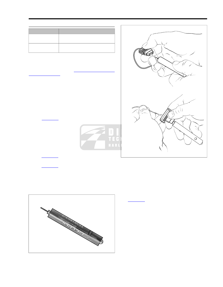
. Obtain the PACKARD MICRO-64 TER-

MINAL REMOVER (Part No. HD-45928).

5.

See 

Figure A-50

. Push the adjacent terminals all the way

into the connector housing and then insert tool into hole
until it bottoms.

6.

Leaving the tool installed, gently tug on wires to pull either
one or both terminals from wire end of connector. Remove
tool.

sm00046

Figure A-49. Packard Micro 64 Terminal Remover

(HD-45928)

sm00048

Figure A-50. Packard Micro 64 Connector: Insert Tool and

Remove Terminal

Installing Terminal

1.

Insert terminal into its respective numbered chamber on
wire end of connector. No special orientation of the ter-
minal is necessary.

NOTE

See 

Figure A-51

. For wire location purposes, the corners of

the socket housing are stamped (3) with the numbers 1, 6, 7
and 12, representing terminals 1-6 on one side, and 7-12 on
the other.

2.

Bottom the terminal in the chamber and then gently tug
on the wire to verify that it is locked in place.

NOTE

Once the terminal is removed it may not lock in place when
first reinstalled. Until the lock engages, move the terminal back
and forth slightly while wiggling the lead.

3.

Since the terminal remover tool releases two terminals
simultaneously, repeat step 2 on the adjacent terminal
even if it was not pulled from the connector housing.

2008 Touring Service:  Appendix A Connector Repair  A-33

4.

With the center ear on the head of the secondary lockpin
facing the mating end of the connector, push secondary
lock in until head is flush with the connector housing.

Preparing Wire Leads for Crimping

Strip lead removing  1/8 in. (3.0 mm) of insulation.

Crimping Terminals

1.

Inspect new socket terminal for bent or deformed contact
and crimp tails. Replace as necessary.

2.

See 

Figure A-53

. Squeeze the handles of the PACKARD

MICRO-64 TERMINAL CRIMPER (Part No. HD-45929)
to cycle the tool to the fully open position (1).

3.

Raise locking bar and barrel holder by pushing up on
bottom tab with index finger (2).

4.

With the crimp tails facing upward, insert terminal through
locking bar into front hole in barrel holder (20-22 gauge
wire) (3).

5.

Release locking bar to lock position of contact. When
correctly positioned, the locking bar fits snugly in the space
at the front of the core crimp tails and the closed side of
the terminal rests on the outer nest of the crimp tool.

6.

Insert wires between crimp tails until ends make contact
with locking bar. Verify that wire is positioned so that wide
pair of crimp tails squeeze bare wire strands, while the
narrow pair folds over the insulation material.

7.

Squeeze handle of crimp tool until tightly closed (4). Tool
automatically opens when the crimping sequence is com-
plete.

8.

Raise locking bar and barrel holder to remove contact.

Inspecting Crimps

Inspect the quality of the core and insulation crimps. Distortion
should be minimal.

1

2

3

4

5

6

7

8

9 10

11 12

1

6

7

12

1

2

3

sm00047

1.

Secondary lock

2.

Pin hole

3.

Stamped number

Figure A-51. Packard Micro 64 Connector: Housing

sm00045

Figure A-52. Packard Micro 64 Terminal Crimper (HD-45929)

A-34  2008 Touring Service:  Appendix A Connector Repair

3

1

2

4

sm00049

1.

Open position

2.

Raising locking bar

3.

Insert terminal

4.

Crimp terminal

Figure A-53. Packard Micro 64 Connector: Terminal in

Crimper

2008 Touring Service:  Appendix A Connector Repair  A-35

1

2

sm04684

1.

Front left caliper (screen removed)

2.

Rear caliper

Figure 1-25. Brake Caliper Pad Pin

13. Install new brake pads as follows:

a.

Hold inner brake pad, so that pad pin tab is on the
same side as pad pin hole in caliper. See 

Figure 1-26

.

b.

Insert opposite side of brake pad into caliper engaging
square shaped corner of pad in slot of caliper. See

Figure 1-27

.

c.

Push pad pin tab side of brake pad into caliper until
seated.

d.

Verify that brake pad friction material faces brake disc
gap in caliper.

e.

Repeat step to install outer brake pad.

14. Turn caliper over. Verify that pad pin tabs are centered

under forks of pad spring. Adjust pads if necessary.

15. Install new pad pin and tighten to 75-102 in-lbs (8.5-11.5

Nm).

16. Install retaining clip in groove of pad pin, so that lip over-

hangs caliper housing. See 

Figure 1-28

.

17. Install brake caliper onto brake disc. Align holes in brake

caliper with those in caliper bracket and install two screws.
Alternately tighten screws to 43-48 ft-lbs (58.3-65.1 Nm).

18. If ABS equipped, install new cable strap  1.25 in.  (31.8

mm) in front of the brake hose crimp capturing rear wheel
speed sensor cable and brake hose.

After servicing brakes and before moving motorcycle,
pump brakes to build brake system pressure. Insufficient
pressure can adversely affect brake performance, which
could result in death or serious injury. (00279a)

19. Depress brake pedal several times to set brake pads to

proper operating position within caliper.

20. Check brake fluid level in master cylinder reservoir. If

necessary, add D.O.T. 4 BRAKE FLUID until level is flush
with ledge cast at front of reservoir. See 

Figure 1-29

.

21. Install master cylinder reservoir cover. Install cover screws

and tighten to 12-15 in-lbs (1.4-1.7 Nm).

22. Install right side saddlebag. See 

2.27 SADDLEBAGS,

Installation

.

After repairing the brake system, test brakes at low speed.
If brakes are not operating properly, testing at high speeds
can cause loss of control, which could result in death or
serious injury. (00289a)

23. Test brake system.

a.

Turn ignition switch ON. Depress brake pedal to verify
operation of brake lamp.

b.

Test ride motorcycle. Bleed the system if brakes feel
spongy. See 

1.14 BLEEDING BRAKES

.

NOTE

Avoid making hard stops for the first  100 miles (160 km). This
allows the new pads to become conditioned to the brake discs.

2

3

4

5

1

sm04673

1.

Square corner

2.

Pad pin tab

3.

Pad pin hole

4.

Friction material

5.

Wear indicator lines

Figure 1-26. Brake Pad

2008 Touring Service:  Maintenance  1-33

sm04686

Figure 1-27. Brake Caliper (Bottom View)

2

3

1

sm04685

1.

Pad spring (forked end)

2.

Pad pin tab

3.

Pad pin retaining clip

Figure 1-28. Brake Caliper (Top View)

Front Brake Calipers

1.

If present, carefully cut two cable straps to release front
wheel speed sensor cable and front fender tip lamp wires
from brake hose to left brake caliper.

2.

On ABS equipped motorcycles, release front wheel speed
sensor cable from clip as follows:

a.

Push on lip at rear of clip to disengage from bracket.

b.

Rotate tab (stamped ABS) rearward until clip is per-
pendicular to bracket and remove cable.

3.

Remove two brake caliper mounting screws (with cable
clip/bracket if ABS equipped). Slide brake caliper straight

down to remove from brake disc. Allow the brake caliper
to hang loose.

NOTE

Do not operate the brake lever with the front brake caliper
removed or the caliper pistons may be forced out. Reseating
pistons requires caliper disassembly.

4.

Resting motorcycle on jiffy stand, turn front wheel toward
left fork stop until front master cylinder reservoir is level.
Wrap a clean shop cloth around the outside of the reservoir
to protect paint from brake fluid spills.

5.

Remove two screws to release cover from master cylinder
reservoir.

NOTE

Fluid level will rise as pistons are pushed back into the caliper,
possibly overflowing the master cylinder reservoir. Remove
some fluid from the reservoir if necessary.

6.

Alternately push each pad back until pistons are fully
seated in the bores.

7.

Pull screen from caliper.

8.

Pull retaining clip from groove in pad pin. See 

Figure 1-28

.

9.

Remove pad pin (metric). See 

Figure 1-25

.

10. Pull on pad pin side of brake pads to release from caliper.

11. Remove pad spring if damaged or worn.

12. If removed, seat new pad spring on flat in caliper, so that

clips on spring engage indentations in caliper. Be sure
that forked end of pad spring is on the pad pin side of the
caliper.

Always replace brake pads in complete sets for correct
and safe brake operation. Improper brake operation could
result in death or serious injury. (00111a)

13. Install new brake pads as follows:

a.

Hold inner brake pad, so that pad pin tab is on the
same side as pad pin hole in caliper. See 

Figure 1-26

.

b.

Insert opposite side of brake pad into caliper engaging
square shaped corner of pad in slot of caliper. See

Figure 1-27

.

c.

Push pad pin tab side of brake pad into caliper until
seated.

d.

Verify that brake pad friction material faces brake disc
gap in caliper.

e.

Repeat step to install outer brake pad.

14. Turn caliper over. Verify that pad pin tabs are centered

under forks of pad spring. Adjust pads if necessary.

15. Install new pad pin and tighten to 75-102 in-lbs (8.5-11.5

Nm).

16. Install retaining clip in groove of pad pin, so that lip over-

hangs caliper housing. See 

Figure 1-28

.

17. Engaging two prongs on screen beneath forked end of

pad spring, push on single prong side of screen until
engaged.

1-34  2008 Touring Service:  Maintenance

18. Install brake caliper as follows:

a.

With the bleeder valve topside, install caliper at
bottom of brake disc.

b.

Slide brake caliper straight up until holes are aligned
with lugs on fork slider. Start two mounting screws
(with cable clip/bracket if ABS equipped).

NOTE

Be sure that tab (stamped ABS) on clip is installed in slot
of bracket from inboard side. Clip cannot be installed once
mounting screws are started.

c.

Alternately tighten mounting screws to 28-38 ft-
lbs (37.9-51.5 Nm)

After servicing brakes and before moving motorcycle,
pump brakes to build brake system pressure. Insufficient
pressure can adversely affect brake performance, which
could result in death or serious injury. (00279a)

19. If ABS equipped, install two new cable straps as follows:

a.

Install cable strap  2.5 in. (63.5 mm) above the bottom
brake hose crimp capturing front wheel speed sensor
cable and brake hose.

b.

Install cable strap  2.5 in. (63.5 mm) below the top
brake hose crimp capturing front wheel speed sensor
cable, brake hose and front fender tip lamp wires, if
equipped.

20. If ABS equipped, install front wheel speed sensor cable

in clip as follows:

a.

Rotate tab (stamped ABS) until clip is perpendicular
to bracket and install cable.

b.

Rotate tab forward until clip is in-line with bracket and
then apply pressure to tab until lip engages. Gently
pull on cable to verify that clip is properly installed.

21. Repeat applicable steps to replace brake pads in right

side caliper.

After servicing brakes and before moving motorcycle,
pump brakes to build brake system pressure. Insufficient
pressure can adversely affect brake performance, which
could result in death or serious injury. (00279a)

22. Depress brake lever several times to set brake pads to

proper operating position within caliper.

23. Check brake fluid level in master cylinder reservoir. If

necessary, add D.O.T. 4 BRAKE FLUID until level is flush
with step (marked MAX) cast at rear of reservoir. See

Figure 1-29

.

24. Install master cylinder reservoir cover. Install cover screws

and tighten to 7-10 in-lbs (0.8-1.1 Nm).

After repairing the brake system, test brakes at low speed.
If brakes are not operating properly, testing at high speeds
can cause loss of control, which could result in death or
serious injury. (00289a)

25. Test brake system.

a.

Turn ignition switch ON. Depress brake lever to verify
operation of brake lamp.

b.

Test ride motorcycle. Bleed system if brakes feel
spongy. See 

1.14 BLEEDING BRAKES

.

NOTE

Avoid making hard stops for the first  100 miles (160 km). This
allows the new pads to become conditioned to the brake discs.

1

2

sm04727

1.

Front master cylinder reservoir

2.

Rear master cylinder reservoir

Figure 1-29. Brake Fluid Level

2008 Touring Service:  Maintenance  1-35

1.16

BATTERY MAINTENANCE

GENERAL

Batteries contain sulfuric acid, which could cause severe
burns to eyes and skin. Wear a protective face shield,
rubberized gloves and protective clothing when working
with batteries. KEEP BATTERIES AWAY FROM CHILDREN.
(00063a)

Never remove warning label attached to top of battery.
Failure to read and understand all precautions contained
in warning, could result in death or serious injury. (00064a)

Batteries, battery posts, terminals and related accessories
contain lead and lead compounds, and other chemicals
known to the State of California to cause cancer, and birth
defects or other reproductive harm. Wash hands after
handling. (00019e)

All AGM batteries are permanently sealed, maintenance-free,
valve-regulated, lead/calcium and sulfuric acid batteries. The
batteries are shipped pre-charged and ready to be put into
service. Do not attempt to open these batteries for any reason.

NOTE

For charging information, see 

1.16 BATTERY MAINTENANCE,

Charging Battery

. For testing information, see ELECTRICAL

DIAGNOSTIC MANUAL.

is00249

Figure 1-30. AGM Battery with Warning Label

4

1

2

3

5

6

sm02241

4.

1.

Keep flames away

Contents are corrosive

2.

5.

Wear safety glasses

Read instructions

6.

3.

Keep away from children

Contents are explosive

Figure 1-31. Battery Warning label

1-36  2008 Touring Service:  Maintenance


Content      ..     6      7      8      9     ..