Harley Davidson 2004 Touring Models. Service Manual - page 37
HOME
11. Bend tabs on lockplates away from flats of four fender
11.
Remove drill bit from axle hole.
mounting bolts. Remove fender mounting bolts and lock-
12.
Install brake caliper as follows:
plates. Remove fender from vehicle.
a. Use shop rag or tape to protect fender area adja-
cent to caliper, as incidental contact can occur dur-
ing caliper installation.
INSTALLATION
b. With the bleeder valve topside, position caliper so
that brake disc is situated between friction pads.
Now align upper mounting hole in caliper with upper
NOTE
mounting lug on fork leg.
If fender tip lamp is absent, perform steps 1 and 3-12.
c. Loosely install long caliper mounting bolt into upper
lug of front fork leg.
1. Align mounting holes in fender and lockplates with those
in fork tubes. Install four fender mounting bolts and
d. Install short caliper mounting bolt into lower lug of
tighten to 16-20 ft-lbs (22-27 Nm). Bend tabs on lock-
front fork leg. Tighten lower mounting bolt to 28-38
plates against flats of fender mounting bolts.
ft-lbs (37.9-51.5 Nm).
2. Route socket housing of front fender tip lamp connector
e. Tighten upper caliper mounting bolt to 28-38 ft-lbs
upward behind chrome skirt (FLHT/C/U) or through bot-
(37.9-51.5 Nm).
tom of headlamp nacelle (FLHR) to area beneath upper
f.
Repeat step 12 to install caliper on opposite side of
fork bracket. Mate pin and socket halves.
wheel.
NOTE
13.
Install new cable strap to secure front fender tip lamp
To connect front fender tip lamp with the outer fairing
wires to brake line hose. Cut any excess cable strap
installed (FLHT/C/U models), reach in below the fairing cap
material.
on the left side of the steering head.
14.
FLHT/C/U: Install the outer fairing, if removed. See Sec-
3. Place wheel into position between forks with the valve
tion 2.29 UPPER FAIRING/WINDSHIELD (FLHT/C/U),
stem on the right side of the vehicle.
OUTER FAIRING/WINDSHIELD, INSTALLATION.
4. Coat the axle with ANTI-SIEZE LUBRICANT.
FLHR: Install wire connector at the back of the head-
lamp bulb. Align holes in headlamp housing with those in
5. Supporting wheel, insert threaded end of axle through
headlamp nacelle. Install eight Phillips screws. Install
right fork leg. Push axle through fork, short external
the headlamp door (chrome ring) and door screw.
spacer and wheel hub until it begins to emerge from left
side.
6. With the three notches on the bearing side, push axle
through long external spacer and left fork leg until axle
shoulder contacts external spacer on right fork side.
7.
Install flat washer, lockwasher and axle nut.
8.
Insert screwdriver or steel rod through hole in axle on
right side of vehicle. While holding axle stationary,
tighten axle nut to 50-55 ft-lbs (68-75 Nm).
9.
Insert 7/16 inch drill bit into hole in axle.
10. Pull fork leg so that it just contacts drill bit, and then
tighten axle holder nuts to 132-180 in-lbs (14.9-20.3
Nm).
2-142
2004 Touring: Chassis
HOME
REAR FENDER
2.33
REMOVAL
f2279x2x
T40 TORX
Bolt
1.
Place the motorcycle on a hydraulic center stand with
the rear wheel raised off the ground.
2.
Remove seat. See Section 2.24 SEAT, REMOVAL.
3.
Remove rear wheel. See Section 2.4 REAR WHEEL,
REMOVAL.
4.
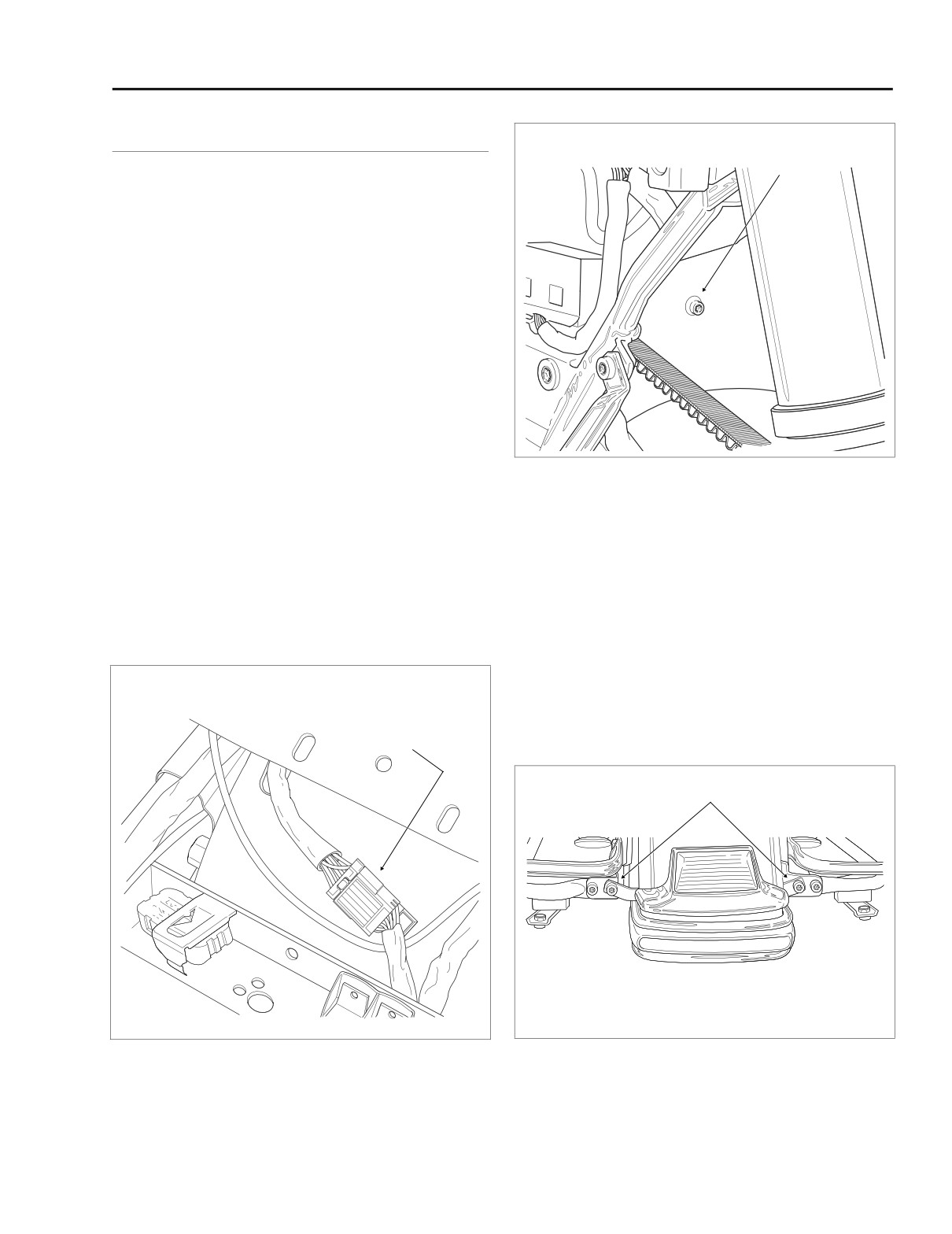
Disconnect the rear fender lights connector anchored at
the front of the rear fender. Depress the button on the
socket terminal side and pull apart the pin and socket
halves. Release anchor from fender hole. See Figure 2-
179.
5.
Gently pull side cover from frame downtube (no tools
required). Repeat step on opposite side of vehicle.
6.
Remove four screws (two on FLHR/C/S and FLTR) to
release license plate bracket from luggage rack.
Figure 2-180. Rear Fender Front Mounting Bolt
(Left Side View)
7.
Standing on left side of vehicle, use a T40 TORX drive
head to release front of rear fender from battery box.
See Figure 2-180.
9.
Reaching under bumper, remove nut (with flat washer) to
free bumper bracket from weld stud on fender. Remove
8.
At rear of vehicle, remove inside bolt (and flange nut) to
bumper from vehicle.
release rear bumper support rail from saddlebag support
bracket and saddlebag support rail. Repeat step on
10.
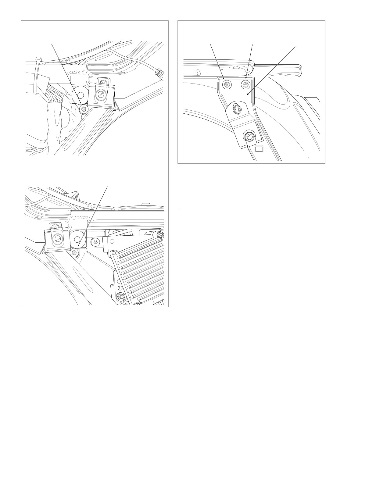
Using a T40 TORX drive head, remove fender side
opposite side of vehicle. See Figure 2-181.
mounting bolt located just below side cover grommet.
Repeat step on opposite side of vehicle. See Figure 2-
182.
11.
Using a T40 TORX drive head, remove upper rear bolt
f2013x8x
from saddlebag support bracket. Repeat step on oppo-
Rear Fender
site side of vehicle. See Figure 2-183.
Lights Connector [7]
T40 TORX Bolt
f1908x2x
Figure 2-179. Rear Fender (Top View)
Figure 2-181. Release Bumper From Saddlebag Rail
2004 Touring: Chassis
2-143
HOME
T40
T40
LEFT SIDE
T40
TORX Bolt
TORX Bolt
Saddlebag
TORX Bolt
Front
Rear
Support Bracket
f1862x2x
f1864x2x
f1991x2x
Figure 2-183. Saddlebag Support Bracket Bolts
RIGHT SIDE
(Left Side View)
T40
TORX Bolt
INSTALLATION
1.
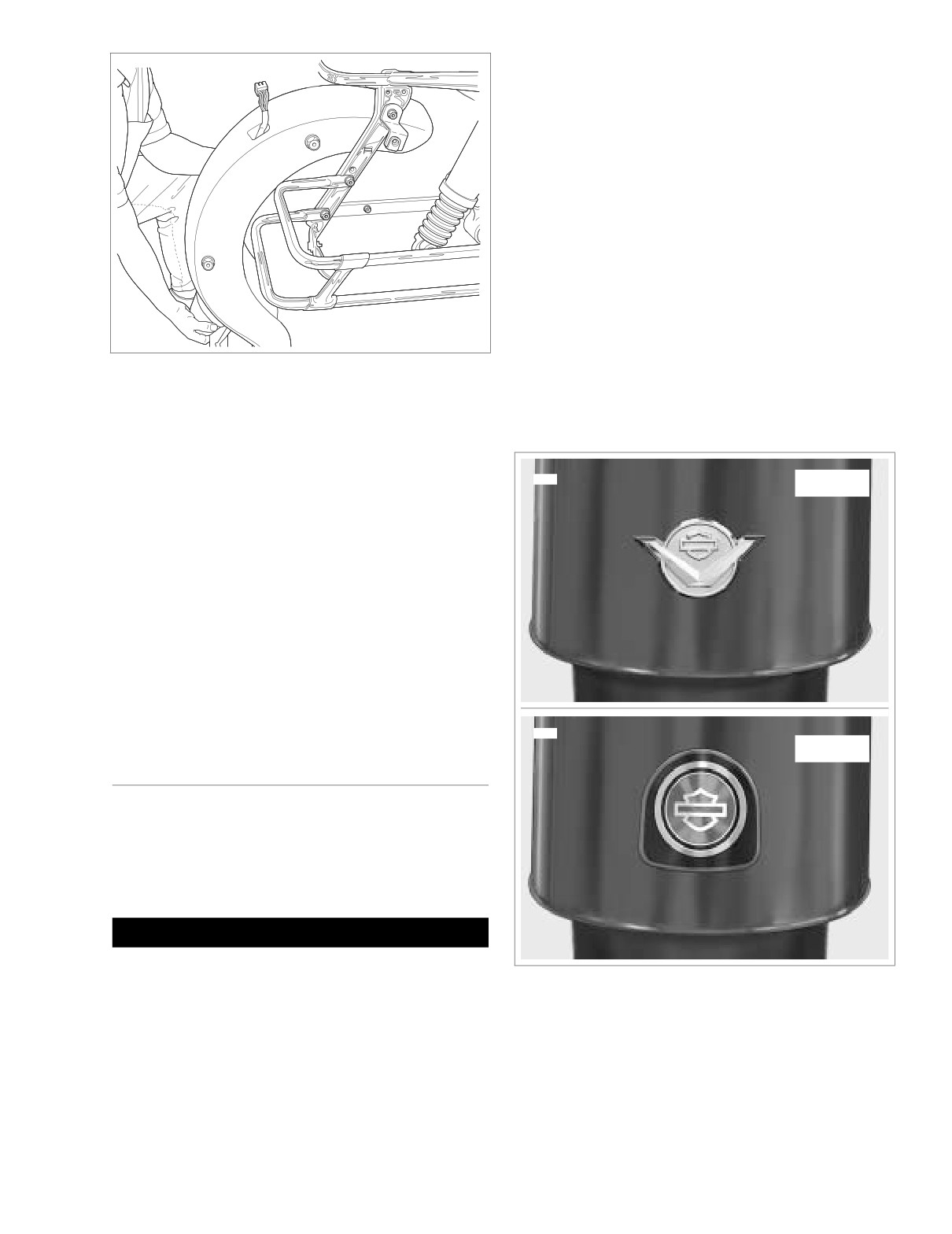
Exercising caution to avoid scratching fender paint on
luggage rack or other bracketry, carefully roll the fender
in. See Figure 2-184. If necessary, have one person
spread the saddlebag support brackets while the other
rolls the fender in.
2.
Engaging hole of fender rear spacer nut, use a T40
TORX drive head to start upper front bolt in saddlebag
support bracket. Repeat step on opposite side of vehi-
cle. See Figure 2-183.
3.
Start upper rear bolt in saddlebag support bracket.
Repeat step on opposite side of vehicle.
4.
Standing on left side of vehicle, start bolt securing front
Figure 2-182. Rear Fender Side Mounting Bolts
of rear fender to battery box. See Figure 2-180.
5.
Engaging hole in frame and fender front spacer nut, start
fender side mounting bolt located just below side cover
12.
Remove upper front bolt from saddlebag support
grommet. Repeat step on opposite side of vehicle. See
bracket. Repeat step on opposite side of vehicle. Be
Figure 2-182.
aware that rear fender will drop when the forward bolts
are removed.
6.
Reaching under rear fender, hang bumper bracket on
fender weld stud. Install flat washer and start nut on
13.
Exercising caution to avoid scratching fender paint on
luggage rack or other bracketry, carefully roll the fender
stud.
out. See Figure 2-184. If necessary, have one person
7.
Start inside bolt (with flange nut) to fasten rear bumper
spread the saddlebag support brackets while the fender
support rail to saddlebag support bracket and saddle-
is rolled out.
bag support rail. Repeat step on opposite side of vehi-
cle. See Figure 2-181.
2-144
2004 Touring: Chassis
HOME
NOTE
Dental floss can be used to gently saw the heated cloisonne
free of the rear fender.
4.
Remove remaining adhesive with 3M GENERAL PUR-
POSE ADHESIVE REMOVER (Part No. 051135).
Installation
1.
Peel backing paper off medallion.
2.
Place medallion in position over recess in rear fender.
NOTE
f2014x2x
The cloisonne is centered left to right over the dimpled
recess in the rear fender with the bottom edge of the cloi-
sonne 1.75 inches (44.45 mm) above the bottom edge of the
Figure 2-184. Carefully Roll Out Rear Fender
fender.
3.
Press firmly to affix cloisonne.
8.
Alternately tighten all rear fender T40 TORX bolts to 15-
20 ft-lbs (20-27 Nm). Tighten nut on fender weld stud to
secure bumper bracket.
9740
FLHRS
9.
Install four screws
(two on FLHR/C/S and FLTR) to
secure license plate bracket to luggage rack.
10.
Mate pin and socket halves of rear fender lights connec-
tor and snap anchor in rear fender hole. See Figure 2-
179.
11.
Align barbed studs in side cover with grommets in frame
downtubes and push firmly into place
(no tools
required). Repeat step on opposite side of vehicle.
12.
Install rear wheel. See Section
2.4 REAR WHEEL,
INSTALLATION.
13.
Install seat. See Section 2.24 SEAT, INSTALLATION.
9741
FLTR
REAR FENDER CLOISONNE
Removal
1. Apply 3M GENERAL PURPOSE ADHESIVE REMOVER
(Part No. 051135) to edge of adhesive backing visible
behind cloisonne. Allow to soak.
CAUTION
Avoid excess heat which will damage the painted sur-
face.
Figure 2-185. Rear Fender Cloisonne
2. Carefully apply heat directly onto cloisonne with ROBIN-
AIR HEAT GUN (HD-25070).
3. Lift the cloisonne from fender.
2004 Touring: Chassis
2-145
HOME
JIFFY STAND
2.34
GENERAL
The vehicle is equipped with a jiffy stand (or side stand) that
locks when placed in the full forward position (down) with the
full weight of the vehicle resting on it.
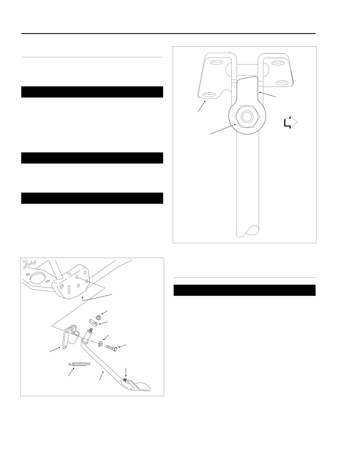
1WARNING
Leg Stop
Without the full weight of the motorcycle resting on the
Longer Side
jiffy stand, any vehicle movement can cause the jiffy
Faces Rear
stand to retract slightly from the full forward position. If
Bracket
the jiffy stand is not in the full forward or lock position
when the full vehicle weight is rested on it, the vehicle
could fall over, which could result in death or serious
Flange
Nut
injury.
1WARNING
Always park the vehicle on a firm, level surface. The
weight of the vehicle can cause it to fall over, which
FRONT
REAR
could result in death or serious injury.
1WARNING
Be sure jiffy stand is fully retracted before riding. If jiffy
stand is not fully retracted during vehicle operation,
unexpected contact with the road surface can distract
the rider. While the jiffy stand will retract upon contact,
f1142a2x
the momentary disturbance and/or rider distraction can
lead to loss of vehicle control resulting in death or seri-
ous injury.
Figure 2-187. Leg Stop Orientation
(Full Forward Position)
REMOVAL
Frame
1WARNING
Hole
Securely block vehicle under frame to be sure that vehi-
Flange
Nut
cle will not fall when jiffy stand is removed. Inadequate
safety precautions could result in death or serious
Leg Stop
injury.
Lockwasher
1.
Block motorcycle under frame, so that vehicle is securely
upright and level. Jiffy stand should be able to move
Bolt
through its full range of travel without the weight of the
vehicle resting on it.
Bracket
Rubber
2.
See Figure 2-186. Move jiffy stand to the retracted posi-
Stop
tion (up). Remove flange nut and leg stop from threaded
end of jiffy stand leg.
Spring
3.
Move jiffy stand to the full forward position
(down).
Jiffy
Stand
Grasping end of spring as close to frame tube as possi-
f1852x2x
ble, twist and turn end with needle nose pliers to unhook
Figure 2-186. Jiffy Stand Assembly
from frame hole. Remove jiffy stand leg from bracket.
2-146
2004 Touring: Chassis
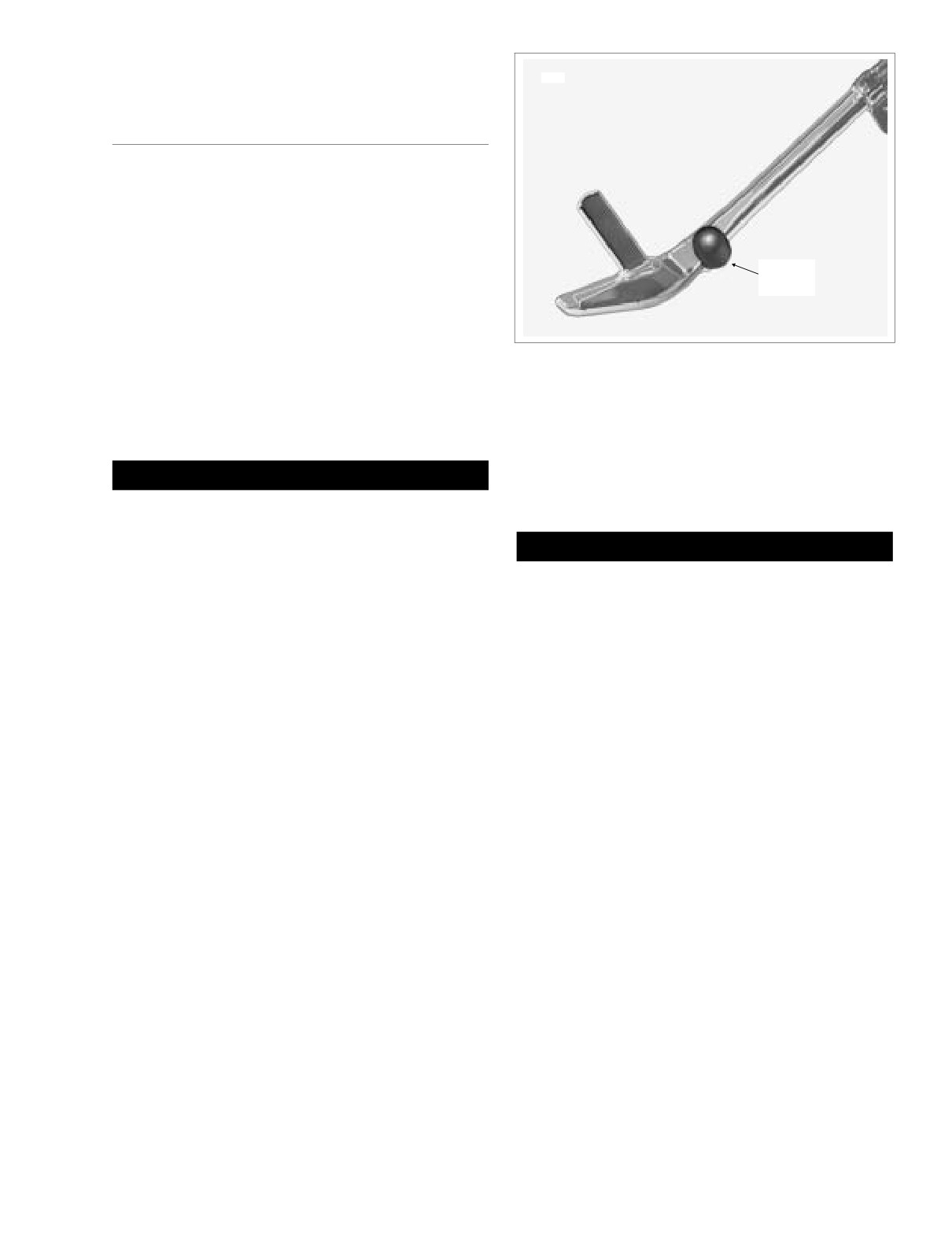
HOME
4. Inspect jiffy stand assembly for worn or damaged parts.
Replace parts as necessary.
7846
INSTALLATION
1. Lubricate the jiffy stand leg with Loctite Aerosol Anti-
Seize Lubricant. Restrict the application to the area of
the jiffy stand leg that rotates within the bracket.
2. Insert threaded end of jiffy stand up through bottom of
bracket. With jiffy stand in the full forward position, par-
tially place spring end into frame hole. Rap spring with a
Rubber
rubber mallet to fully seat in hole.
Stop
NOTE
Verify that opposite end of spring enters hole at front of leg
weldment. If end enters hole from rear, spring coil will rub on
Figure 2-188. Jiffy Stand
leg when jiffy stand is exercised.
3. Holding jiffy stand at the full forward position, install leg
5.
Extend and retract jiffy stand leg several times to verify
stop over threaded end with the stamped “side down.”
proper operation. Jiffy stand should swing freely to the
Install flange nut and tighten to 43-53 ft-lbs (58-72 Nm).
fully extended and fully retracted positions.
6.
Move jiffy stand to the full forward position. Carefully
1WARNING
remove support blocking from beneath motorcycle frame
and rest motorcycle on jiffy stand.
If leg stop is installed incorrectly, excess wear may
cause the vehicle to fall over when rested on the jiffy
stand, which could result in death or serious injury.
CAUTION
4.
Verify that the longer side of the leg stop faces the rear
Verify that rubber stop is in place on prong of jiffy stand.
of the vehicle. See Figure 2-187.
Without the rubber stop, the stand will make hard con-
tact with the lower frame tube when retracted, possibly
resulting in chipping or nicking of the powder coat.
Replace rubber stop if torn or deteriorated. See Figure 2-
188.
2004 Touring: Chassis
2-147
HOME
FOOTBOARDS/FOOTRESTS
2.35
RIDER FOOTBOARD
INSTALLATION
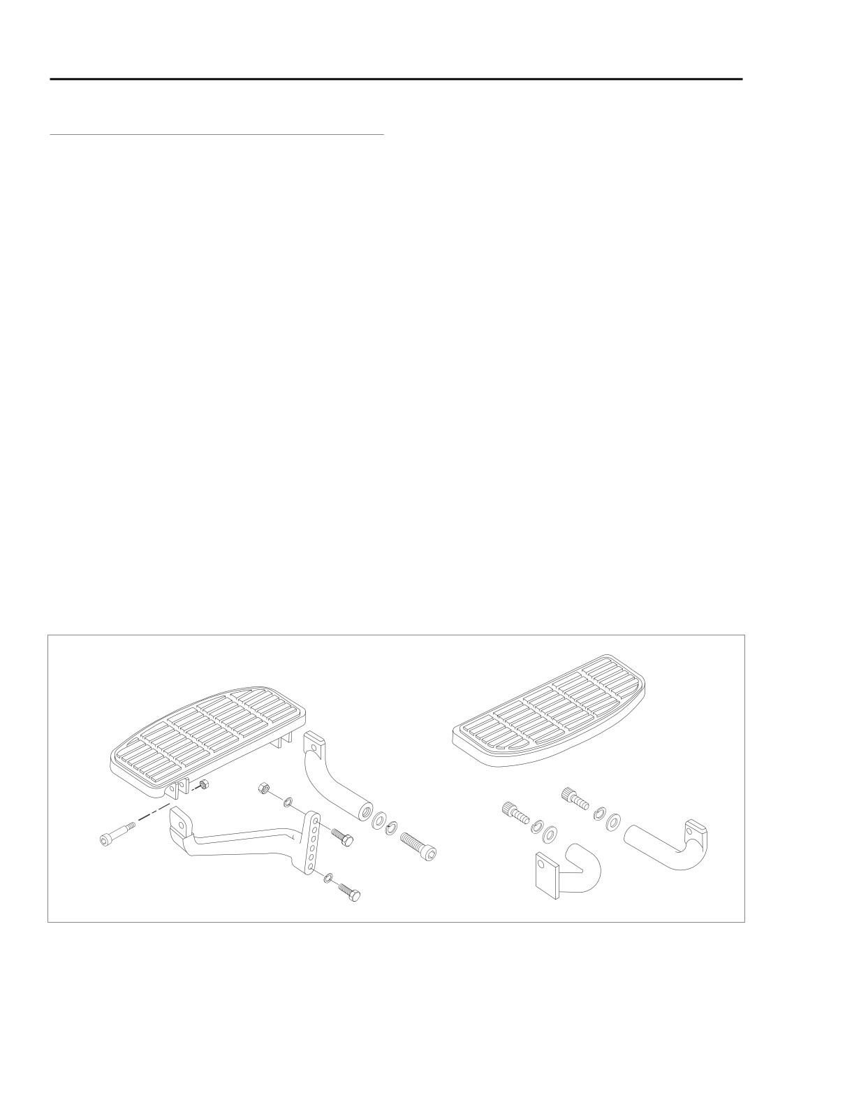
1.
Install right side footboard and bracket assembly as fol-
lows:
REMOVAL
a. Insert two allen head socket screws (with lockwash-
1.
Remove right side footboard and bracket assembly as
ers and flat washers) through frame weldment into
follows:
footboard brackets. See Figure
2-189. For best
results, approach from left side of motorcycle using
a. Remove two allen head socket screws (with lock
a 3/8 inch ball allen with extension.
washers and flat washers) to release footboard
b. Alternately tighten socket screws to 30-35 ft-lbs (41-
brackets from frame weldment. See Figure 2-189.
48 Nm).
For best results, approach from left side of motorcy-
cle using a 3/8 inch ball allen with extension.
2.
Install left side footboard and bracket assembly as fol-
2.
Remove left side footboard and bracket assembly as fol-
lows:
lows:
a. Insert allen head socket screw (with lockwasher and
flat washer) through frame weldment into footboard
a. Raise the motorcycle on a hydraulic center stand so
forward bracket. See Figure 2-189. For best results,
that the weight of the motorcycle is not resting on
approach from opposite side of motorcycle using a
the jiffy stand.
3/8 inch ball allen with extension.
b. Remove socket screw (with lockwasher and flat
b. At footboard rear bracket, slide upper hex bolt
washer) to release footboard forward bracket from
through frame weldment, jiffy stand bracket and
frame weldment. See Figure 2-189. For best results,
footboard bracket thru hole. Install lockwasher and
approach from opposite side of motorcycle using a
locknut. Slide lower hex bolt through frame weld-
3/8 inch ball allen with extension.
ment and jiffy stand bracket into threaded hole of
footboard bracket.
c. To free footboard rear bracket from frame weldment
and jiffy stand bracket, remove lower hex bolt (with
c. Tighten front bracket socket screw to 30-35 ft-lbs
lockwasher) and upper hex bolt (with lockwasher
(41-48 Nm).
and locknut).
d. Alternately tighten rear bracket hex bolts to 15-20 ft-
lbs (20-27 Nm).
Left Side
Right Side
f2242x2x
Figure 2-189. Rider Footboards (All Models Except FLHRS)
2-148
2004 Touring: Chassis
HOME
DISASSEMBLY
NOTE
If only replacing the rubber pad, refer to step 1 below and
then see steps 4-5 under ASSEMBLY.
1. Tilt footboard upward. From bottom of footboard, use a
large flat blade screwdriver to push four rubber anchors
on pad up through holes in footboard.
2. Remove nuts from pivot bolts at underside of footboard.
3. Remove pivot bolts to release footboard from brackets.
4. Remove footboard brackets. See RIDER FOOT-
BOARD, REMOVAL, in this section.
ASSEMBLY
f2243x2x
1. Install footboard brackets. See RIDER FOOTBOARD,
INSTALLATION, in this section.
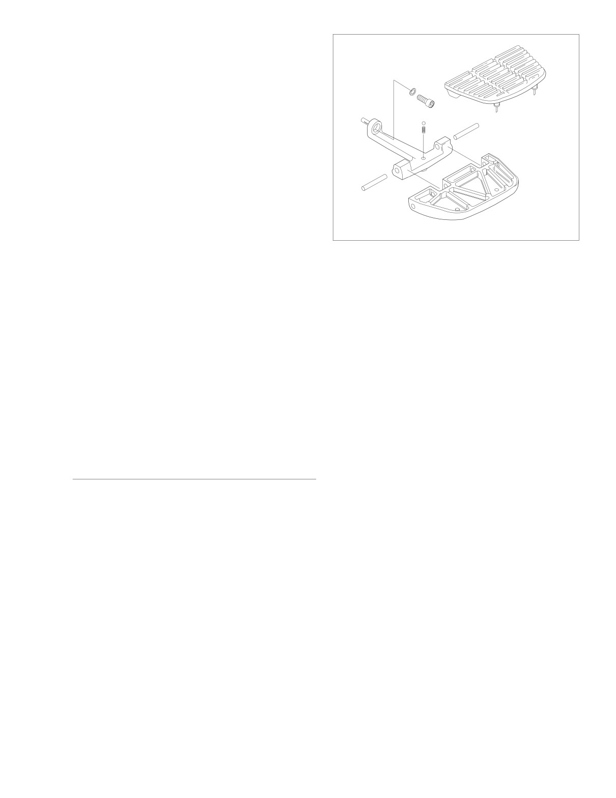
Figure 2-190. Passenger Footboard
(All Models Except FLHRS)
2. Place footboard into position between brackets and
install pivot bolts so that the nuts will be on the inboard
side.
DISASSEMBLY
NOTE
NOTE
The bottom of FLHRS footboards are stamped L(eft) or
If only replacing the rubber pad, refer to step 1 below and
R(ight) to ensure proper installation.
then see steps 4-5 under ASSEMBLY.
3. Install nuts onto pivot bolts and alternately tighten to 84-
1.
Tilt footboard upward. From bottom of footboard, use a
108 in-lbs (9.5-12.2 Nm).
small flat blade screwdriver to push rubber beads on pad
up through holes in footboard. Remove pad.
4. Moisten four rubber anchors on new pad with soapy
water.
2.
Using a brass drift and rubber mallet, tap two retaining
pins toward center of footboard and remove.
5. Place pad into position on footboard. From bottom of
3.
Remove footboard from bracket.
footboard, use pliers to pull rubber anchors down
through holes in footboard.
4.
Remove steel ball and spring from hole in footboard
bracket.
5.
Remove footboard bracket from rear swingarm bracket.
See PASSENGER FOOTBOARD, REMOVAL, in this
PASSENGER FOOTBOARD
section.
REMOVAL
ASSEMBLY
1. Remove socket screw with lockwasher to remove foot-
1.
Install footboard bracket. See PASSENGER FOOT-
board bracket from rear swingarm bracket.
BOARD, INSTALLATION, in this section.
2.
Place spring into hole in footboard bracket. Place ball on
top of spring.
INSTALLATION
3.
Place footboard into position on bracket and install
1. Insert pin on footboard bracket into hole in swingarm
retaining pins from the outboard side. Using a brass drift
bracket.
and rubber mallet, tap pins until centered in lugs of
bracket.
NOTE
4.
Moisten rubber beads on new pad with soapy water.
Passenger footboards can be adjusted to one of three posi-
Place pad into position on footboard. From bottom of
tions. To move footboards to a new position, remove plastic
footboard, use needle nose pliers to pull rubber beads
plugs from holes in rear swingarm bracket as necessary.
down through holes in footboard.
2. Install socket screw with lockwasher. Tighten socket
5.
Engage nubs on inboard corners of pad with holes in
screw to 15-18 ft-lbs (20-24 Nm).
footboard.
2004 Touring: Chassis
2-149
HOME
PASSENGER FOOTREST (FLHRS)
ASSEMBLY
1.
Install footrest bracket. See PASSENGER FOOTREST
(FLHRS), INSTALLATION, in this section.
REMOVAL
1.
Remove socket screw with lockwasher to remove foot-
2.
With concave side up and flat edge facing opposite the
rest bracket from rear swingarm bracket.
footrest, align hole in wave spring with topside hole in
footrest.
3.
Place footrest with wave spring between arms of bracket
INSTALLATION
and install pivot pin. Hole in bracket is countersunk to
accommodate head of pivot pin.
1.
Insert pin on footrest bracket into hole in swingarm
bracket.
NOTE
NOTE
Verify operation of footrest before installing retaining ring.
Passenger footrests can be adjusted to one of three posi-
The ease with which the footrest pivots is based on the cur-
tions. To move footrests to a new position, remove plastic
vature of the wave spring. Flattening the wave spring allows
plugs from holes in rear swingarm bracket as necessary.
the footrest to move more easily, while increasing the curva-
ture makes movement more difficult.
2.
Install socket screw with lockwasher. Tighten socket
screw to 15-18 ft-lbs (20-24 Nm).
4.
Install new retaining ring in groove at end of pivot pin.
5.
Place new pad into footrest.
DISASSEMBLY
6.
Apply a small dab of Loctite Medium Strength Thread-
NOTE
locker
243 (blue) to threads of socket screw. Install
socket screw and tighten to 15-20 ft-lbs (20-27 Nm).
If only replacing the rubber pad, refer to step 1 below and
then see steps 5-6 under ASSEMBLY.
1.
Remove socket screw from end of footrest. Remove rub-
ber pad.
2. Remove retaining ring from groove at end of pivot pin.
Remove pivot pin.
3. Remove footrest and wave spring from footrest bracket.
4. Remove footrest bracket from rear swingarm bracket.
See PASSENGER FOOTREST (FLHRS), REMOVAL, in
this section.
2-150
2004 Touring: Chassis
HOME
EXHAUST SYSTEM
2.36
NOTE
REMOVAL
TORCA muffler clamps have eliminated the need for silicone
or graphite tape during assembly. To ensure sealing integrity
1. Remove saddlebags. See Section 2.25 SADDLEBAG,
of muffler clamps and prevent the possibility of leakage, Har-
REMOVAL.
ley-Davidson recommends that muffler clamp assemblies be
2. See Figure 2-192. Open worm drive clamps to remove
discarded and replaced each time they are removed.
six heat shields from exhaust pipes. Mark the location of
the heat shields to ensure proper assembly.
3. Using a bungee cord, tie the muffler on the left side of
INSTALLATION
the vehicle to the lower saddlebag support rail.
4. Remove the exhaust flange nuts to release the front and
NOTE
rear header pipes from the cylinder head studs. For best
Always loosely assemble exhaust system on vehicle before
results, use impact wrench with long 1/2 inch swivel
following tightening procedure. Assemble as follows:
socket.
1.
Install new gaskets in both the front and rear cylinder
5. See Figure 2-191. Loosen the four TORCA clamps as
head exhaust ports (with the tapered side out).
follows:
Right side of vehicle
2.
Install transmission exhaust bracket onto transmission
side door, if removed.
● front header pipe to rear header pipe
● rear header pipe to right side muffler
3.
Install front header pipe exhaust flange onto front cylin-
der head. Start flange nuts on cylinder head studs.
Left side of vehicle
4.
Engaging transmission exhaust bracket, capture front
● rear header pipe to crossover pipe
header pipe in transmission exhaust bracket clamp. Use
● crossover pipe to left side muffer
a channel lock to close clamp, if necessary. Finger
NOTE
tighten clamp bolt (with flat washer and locknut).
To facilitate removal, spray PB Blaster or other suitable pene-
5.
Slide a new TORCA clamp onto free end of front header
trating oil in and around joints of exhaust pipes. For best
pipe.
results, be sure to allow sufficient time for the penetrating oil
6.
Install rear header pipe onto rear cylinder head and front
to work.
header pipe. Start flange nuts on cylinder head studs.
6.
Remove four bolts (with lockwashers) to detach left and
Move TORCA clamp into position between front and rear
right side mufflers from the lower saddlebag support
header pipes.
rails.
7.
Slide new TORCA clamps onto free ends of rear header
7.
Standing on right side of vehicle, remove muffler from Y-
pipe. TORCA clamp to crossover pipe is special in that it
shaped rear header pipe.
has slot for bracket tab to exhaust support bracket.
8.
Remove Keps nut and pull bracket tab and stud from
8.
Slide right side muffler onto rear header pipe. Finger
slots in TORCA clamp and exhaust support bracket.
tighten two bolts (with lockwashers) to attach muffler to
9.
Remove Y-shaped rear header pipe from front header
lower saddlebag support rail. Place TORCA clamp into
pipe, crossover pipe (to left side muffler) and rear cylin-
position between rear header pipe and right side muffler.
der head. Remove bracket tab from slot in TORCA
9.
Moving to left side of vehicle, install crossover pipe onto
clamp.
remaining end of rear header pipe (above starter). Place
10.
Remove bolt (with flat washer and locknut) from trans-
TORCA clamp into position between rear header pipe
mission exhaust bracket clamp on front header pipe.
and crossover pipe.
Use a channel lock to open clamp and then remove from
10.
Fit bracket tab into slot of TORCA clamp engaging stud
header pipe and transmission exhaust bracket. Remove
in slot of exhaust support bracket. Start Keps nut on
front header pipe exhaust flange from front cylinder
stud.
head.
11.
Slide new TORCA clamp onto free end of crossover
11.
Moving to left side of vehicle, remove crossover pipe
pipe.
from left side muffler.
12.
Using a bungee cord, tie left side muffler to lower sad-
12.
Remove bungee cord to release left side muffler from
dlebag support rail. Install left side muffler on crossover
lower saddlebag support rail.
pipe. Place TORCA clamp into position between cross-
13.
Remove and discard gaskets from front and rear
over pipe and left side muffler. Finger tighten bolts to
exhaust ports. Discard TORCA clamp bolt assemblies-
attach muffler to saddlebag support rail.
one time usage only.
2004 Touring: Chassis
2-151
HOME
b. Tighten the bottom nut of the rear cylinder head
CAUTION
exhaust flange to 9-18 in-lbs (1-2 Nm). Tighten the
top nut to
100-120 in-lbs (11.3-13.6 Nm). Final
Verify that the exhaust pipes do not contact the vehicle
tighten the bottom nut to 100-120 in-lbs (11.3-13.6
frame or any mounted components. Contact will cancel
Nm).
the effect of the rubber isolation mounts and transmit
c. Tighten the transmission exhaust bracket clamp bolt
vibration to the rider via the vehicle frame.
to 60-96 in-lbs (6.8-10.8 Nm).
13. Tighten the exhaust system as follows:
d. Tighten the two bolts (with lockwashers) to fasten
the right side muffler to the lower saddlebag support
a. Tighten the top nut of the front cylinder head
rail.
exhaust flange to 9-18 in-lbs (1-2 Nm). Tighten the
bottom nut to 100-120 in-lbs (11.3-13.6 Nm). Final
e. Tighten the two bolts (with lockwashers) to fasten
tighten the top nut to
100-120 in-lbs (11.3-13.6
the left side muffler to the lower saddlebag support
Nm).
rail.
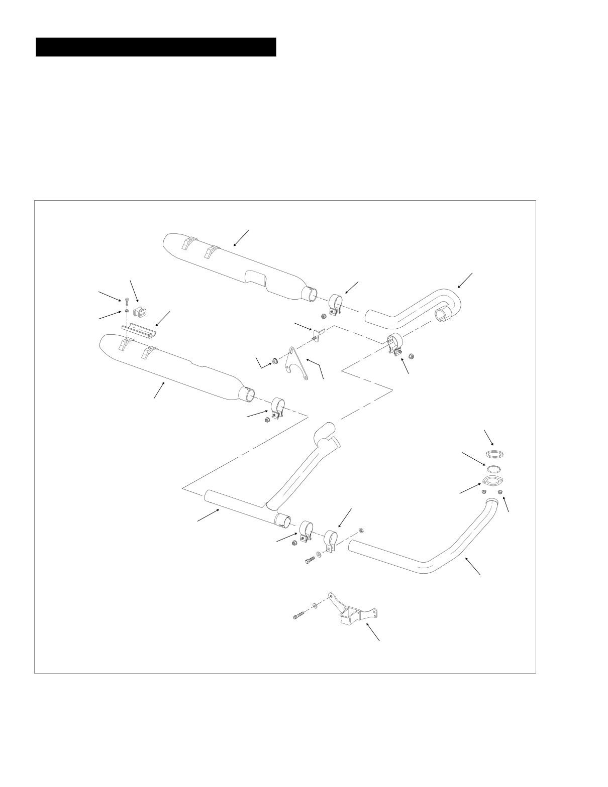
Left
Muffler
Crossover
Rubber
TORCA
Pipe
Mount
Clamp
Screw
Saddlebag Support
Rail Bracket
Bracket
Lock
Tab
Washer
Keps
Nut
TORCA
Exhaust
Clamp
Support Bracket
(Special)
Right
Muffler
Cylinder Head
TORCA
Gasket
Clamp
Circlip
Transmission
Exhaust Bracket
Exhaust
Clamp
Flange
Nut
Rear
Header Pipe
TORCA
Clamp
Front
Header Pipe
Transmission
f1153b2x
Exhaust Bracket
Figure 2-191. Exhaust System (without Heat Shields)
2-152
2004 Touring: Chassis
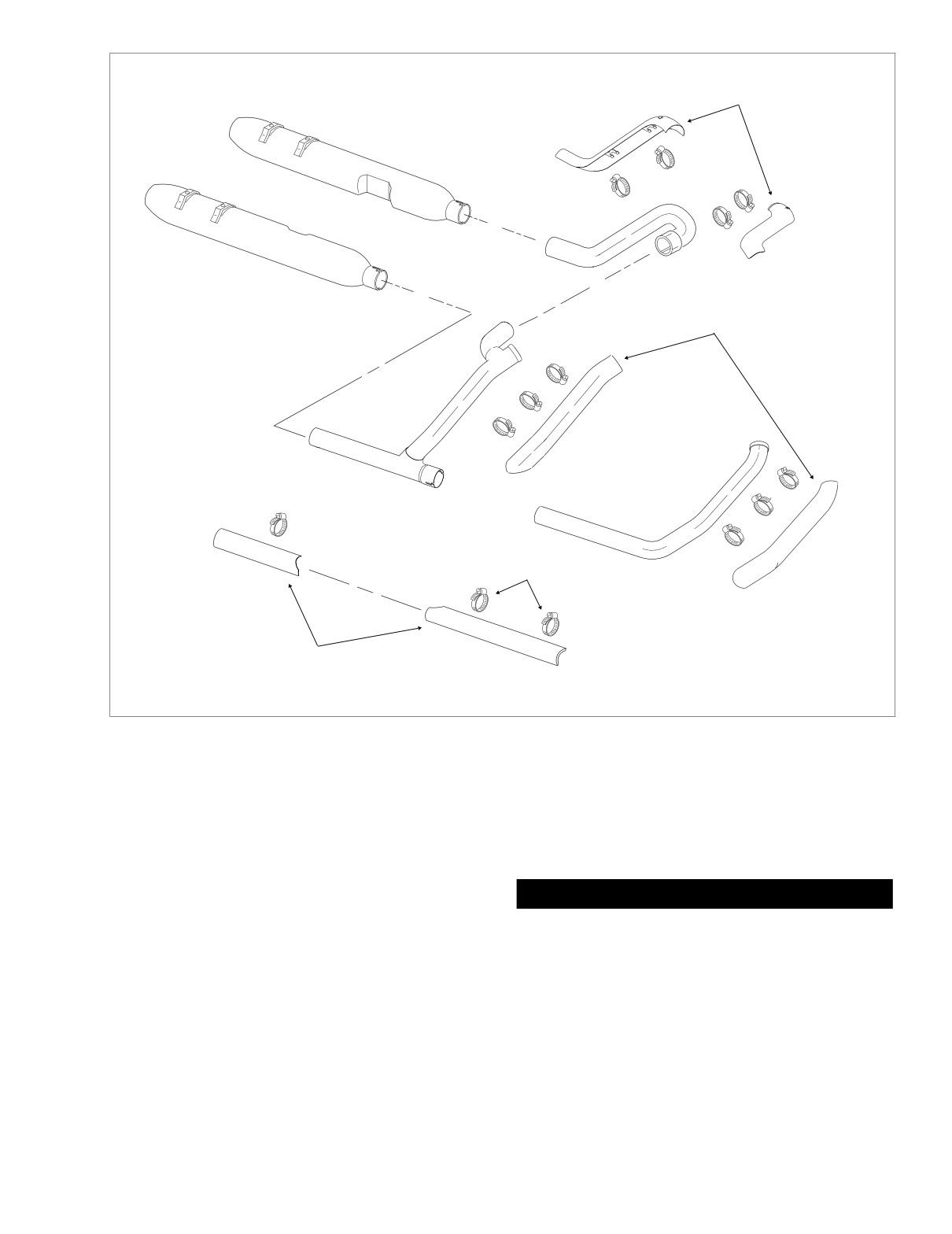
HOME
Heat
Shields
Left Muffler
Crossover
Pipe
Right Muffler
Heat
Shields
Rear
Header Pipe
Worm Drive
Clamps
Front
Header Pipe
Heat
Shields
f1154b2x
Figure 2-192. Heat Shields
f.
Verify that all exhaust pipes are in alignment and do
15. Open worm drive clamps and install six heat shields on
not contact the vehicle frame or mounted compo-
exhaust pipes as marked during removal. See Figure 2-
nents.
192. Position each clamp so that screw is on the out-
board side in the most accessible position and then
g. Tighten the four TORCA clamps to 45-60 ft-lbs (61-
tighten to 20-40 in-lbs (2.3-4.5 Nm).
81 Nm) in the following order:
● crossover pipe to left side muffer
CAUTION
● rear header pipe to right side muffer
Verify that the heat shields do not contact the vehicle
● front header pipe to rear header pipe
frame or any mounted components. Contact will cancel
● rear header pipe to crossover pipe
the effect of the rubber isolation mounts and transmit
vibration to the rider via the vehicle frame.
14. Tighten Keps nut securing bracket tab to exhaust sup-
port bracket.
16. Remove bungee cord from left side muffler.
17. Install saddlebags. See Section
2.25 SADDLEBAG,
INSTALLATION.
2004 Touring: Chassis
2-153
HOME
NOTES
2-154
2004 Touring: Chassis
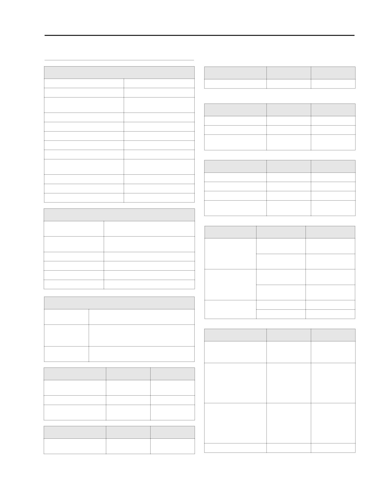
HOME
SPECIFICATIONS
3.1
MANUFACTURING TOLERANCES
General
Hydraulic Lifter
IN.
MM
Number of cylinders
2
Fit in crankcase (loose)
0.0008-0.0020
0.02-0.05
Type
4-cycle, 45˚V2, air-cooled
85 ft-lbs (115.2 Nm) @ 3000
Torque
rpm, chrome dual exhaust
Cylinder Head
IN.
MM
Bore
3.75 in. (95.25 mm)
Valve guide in head (tight)
0.0020-0.0033
0.051-0.084
Stroke
4.00 in. (101.6 mm)
Valve seat in head (tight)
0.003-0.0045
0.076-0.114
Piston displacement (approx.)
88 cu. in. (1450 cc)
Head gasket surface
0-0.006
0-0.0152
Compression ratio
9.0:1
(flatness)
Combustion chamber
5.187 cu. in. (85 cc) bathtub
Twin cams, chain driven with
Cam system
Valve
IN.
MM
spring loaded tensioners
Fit in guide: exhaust
0.0015-0.0033
0.038-0.084
Max. sustained engine speed
5500 rpm
Fit in guide: intake
0.0008-0.0026
0.020-0.066
Idle speed
1000 rpm +/- 50
Seat width
0.040-0.062
1.02-1.58
Weight
165 lbs (74.8 kg)
Stem protrusion from
1.990-2.024
50.55-51.41
cylinder head boss
Ignition System
Sequential, non waste spark,
Type
MAP-N control
Valve Spring
Outer
Inner
Ignition timing:
72-92 lbs
38-49 lbs
20o-30o
1050 rpm (Hot Idle)
@ 1.751-1.848 in.
@ 1.577-1.683 in.
Closed
Spark plug size
12 mm
33-42 kg
17-22 kg
Spark plug type
Harley-Davidson 6R12
@ 44.45-46.9 mm
@ 40.1-42.8 mm
Spark plug gap
0.038-0.043 in. (0.97-1.09 mm)
183-207 lbs
98-112 lbs
@ 1.282-1.378 in.
@ 1.107-1.213 in.
Spark plug torque
12-18 ft-lbs (16-24 Nm)
Open
83-94 kg
44-51 kg
@ 32.6-35.0 mm
@ 28.1-30.8 mm
Oiling System
2.105-2.177 in.
1.926-1.996 in.
Free length
Twin gerotor, dual scavenge, crank mounted
53.47-55.3 mm
48.9-50.7 mm
Pump
and driven, internal oil pump, dry sump
30-38 psi (207-262 kN/m2) at
Pressure
2000 rpm and normal operating temperature
Piston
IN.
MM
of 230o F (110o C)
Fit in cylinder:
10 micron media,
Early Style Piston
0.0006-0.0017
0.015-0.043
Filtration
filtered between pump and engine
Late Style Piston
0.0014-0.0025
0.036-0.064
Ring end gap:
Rocker Arm
IN.
MM
Top compression ring
0.010-0.020
0.25-0.51
Shaft fit in bushing
2nd compression ring
0.014-0.024
0.36-0.61
0.0005-0.0020
0.013-0.051
(loose)
Oil control ring
0.010-0.050
0.25-1.27
End clearance
0.003-0.013
0.08-0.33
Ring side clearance:
Bushing fit in rocker arm
0.002-0.004
0.051-0.102
Top compression ring
0.0012-0.0037
0.030-0.094
(tight)
2nd compression ring
0.0012-0.0037
0.030-0.094
Rocker Arm Shaft
IN.
MM
Oil control ring
0.0031-0.0091
0.079-0.23
Shaft fit in rocker arm
0.0007-0.0022
0.018-0.056
Piston pin fit (loose)
0.0002-0.0005
0.005- 0.013
support plate (loose)
2004 Touring: Engine
3-1
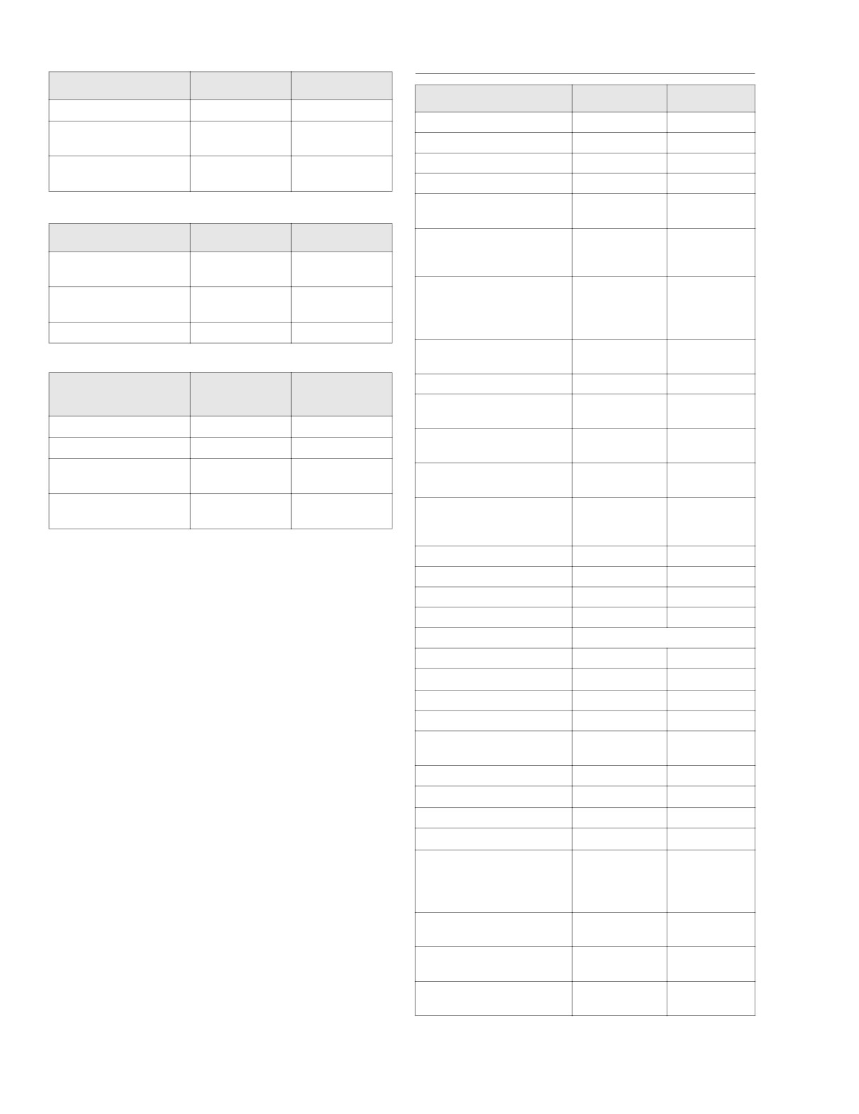
HOME
MANUFACTURING TOLERANCES (CONT.)
TORQUE VALUES
Connecting Rod
IN.
MM
Item
ft/in-lbs
NM
Piston pin fit (loose)
0.0007-0.0012
0.018-0.030
Breather assembly bolts
90-120 in-lbs
10-14 Nm
Side play between
0.005-0.015
0.13-0.38
flywheels
Cam cover screws
125-155 in-lbs
14-18 Nm
Connecting rod to
Cam cover plate screws
20-30 in-lbs
2.3-3.4 Nm
0.0004-0.0017
0.0102-0.0432
crankpin (loose)
Cam support plate screws
90-120 in-lbs
10-14 Nm
Bearing retainer plate
20-30 in-lbs
2-3 Nm
screws
Flywheel
IN.
MM
15 ft-lbs,
20.3 Nm,
Crank sprocket flange bolt
loosen one full
loosen one full
Runout
0.000-0.010
0.000-0.254
turn, 24 ft-lbs
turn, 32.5 Nm
(flywheels at rim)
15 ft-lbs,
20.3 Nm,
Runout
0.000-0.002
0.000-0.051
Primary cam sprocket
loosen one full
loosen one
(shaft at flywheel)
flange bolt
turn, 34 ft-lbs
full turn, 46.1
End play
0.003-0.010
0.076-0.254
Nm
Crank position sensor
90-120 in-lbs
10.2-13.6 Nm
screw
Crankshaft/Sprocket
Piston jet screws
25-35 in-lbs
2.8-4.0 Nm
IN.
MM
Shaft Bearings
Transmission housing to
15 ft-lbs,
20 Nm,
crankcase bolts
30-35 ft-lbs
41-48 Nm
Bearing fit (loose)
0.0002-0.0015
0.005-0.038
Crankcase to front engine
Crankshaft runout
0.0-0.003
0.0-0.076
33-38 ft-lbs
45-52 Nm
mounting bracket bolts
Bearing fit in
0.0038-0.0054
0.097-0.137
10 ft-lbs,
14 Nm,
crankcase (tight)
Crankcase bolts
15-19 ft-lbs
20-26 Nm
Bearing inner race on
120-144 in-lbs,
13.6-16.3 Nm,
0.0004-0.0014
0.010-0.036
crankshaft (tight)
Cylinder head bolts
15-17 ft-lbs
20.3-23.1 Nm
+ 90o turn
+ 90o turn
Cylinder studs
10-20 ft-lbs
14-27 Nm
Engine oil drain plug
14-21 ft-lbs
19-28 Nm
Lifter cover screws
90-120 in-lbs
10-14 Nm
Oil pan screws
84-108 in-lbs
9-12 Nm
Oil filter
1/2-3/4 turn after gasket contact
Oil filter mount
12-16 ft-lbs
16-22 Nm
Crankcase oil fittings/plugs
120-168 in-lbs
13.6-18.9 Nm
Oil hose cover screws
84-108 in-lbs
10-12 Nm
Oil pressure switch/sender
96-120 in-lbs
11-14 Nm
Rocker arm support
18-22 ft-lbs
24-30 Nm
plate bolts
Rocker cover bolts
15-18 ft-lbs
20-24 Nm
Rocker housing bolts
120-168 in-lbs
13.6-18.9 Nm
Spark plugs
12-18 ft-lbs
16-24 Nm
Stator screws
55-75 in-lbs
6.2-8.5 Nm
Upper engine mounting
bracket:
To cylinder heads
35-40 ft-lbs
48-54 Nm
To top stabilizer link
18-22 ft-lbs
24-30 Nm
Engine temperature
120-180 in-lbs
13.6-20.3 Nm
sensor
Intake flange adapter
96-144 in-lbs
10.9-16.3 Nm
screws
Exhaust flange adapter
100-120 in-lbs
11.3-13.6 Nm
nuts
3-2
2004 Touring: Engine
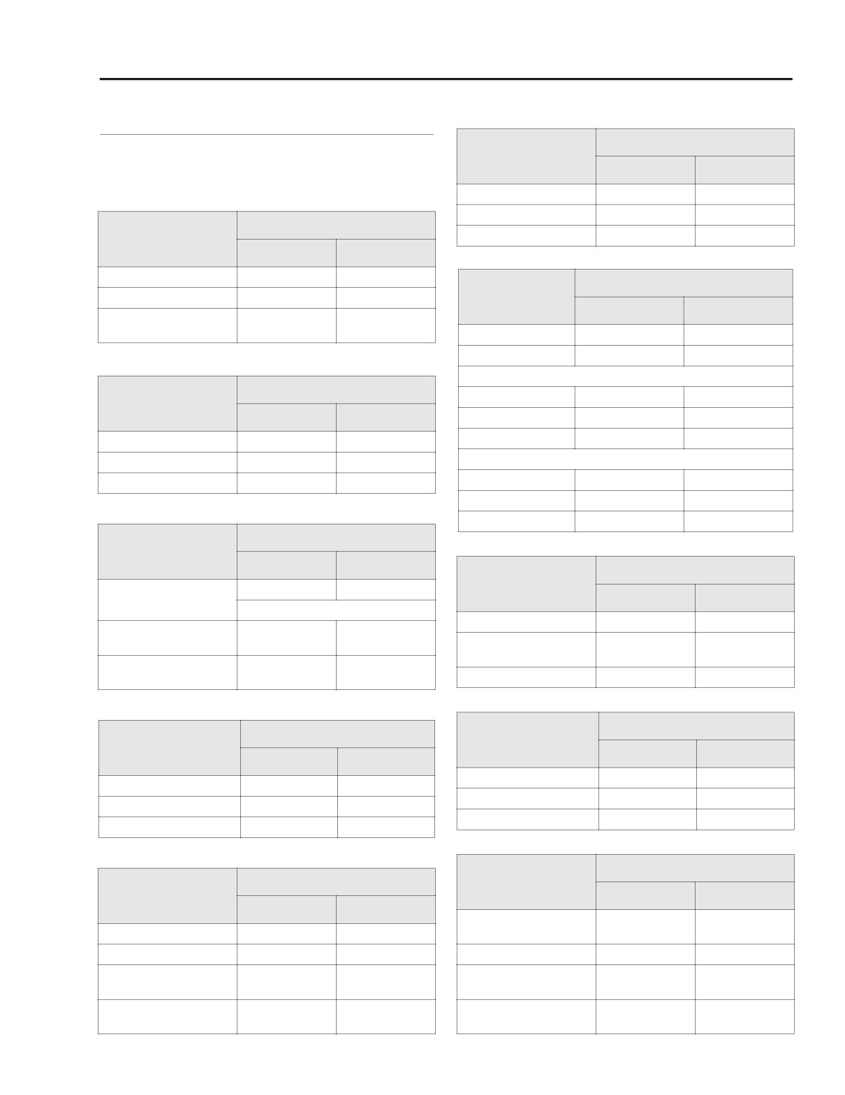
HOME
SERVICE WEAR LIMITS
3.2
GENERAL
REPLACE IF
Wear limits can be used as a guide when deciding whether to
Cylinder Bore
IN.
MM
reuse engine parts. Replace used parts whenever the follow-
ing wear limits are exceeded.
Standard
More than 3.752
More than 95.301
0.005 in. oversize
More than 3.757
More than 95.428
REPLACE IF
Rocker Arm/
0.010 in. oversize
More than 3.762
More than 95.555
Rocker Arm Shaft
IN.
MM
Shaft fit in bushing (loose)
More than 0.0035
More than 0.089
REPLACE IF
End clearance
More than 0.025
More than 0.635
Piston
IN.
MM
Shaft fit in rocker arm
More than 0.0035
More than 0.089
support plate (loose)
Fit in cylinder (loose)
More than 0.003
More than 0.076
Piston pin fit (loose)
More than 0.0008
More than 0.020
Ring end gap
REPLACE IF
Top compression
More than 0.030
More than 0.76
Hydraulic Lifter
IN.
MM
2nd compression
More than 0.034
More than 0.86
Fit in crankcase
More than 0.003
More than 0.08
Oil control ring rails
More than 0.050
More than 1.27
Roller fit
More than 0.0015
More than 0.038
Ring side clearance
Roller end clearance
More than 0.015
More than 0.38
Top compression
More than 0.0045
More than 0.11
2nd compression
More than 0.0045
More than 0.11
Oil control ring rails
More than 0.010
More than 0.25
REPLACE IF
Cam Support Plate
IN.
MM
REPLACE IF
Connecting Rod
More than 0.090
More than 2.29
Cam chain
IN.
MM
tensioner shoe wear
1/2 thickness of shoe
Piston pin fit (loose)
More than 0.002
More than 0.051
Crankshaft bushing fit
Less than 0.0008
Less than 0.0203
in cam support plate
Side play between
More than 0.020
More than 0.508
flywheels
Crankshaft bushing
More than 0.8545
More than 21.704
maximum ID
Fit on crankpin (loose)
More than 0.002
More than 0.051
REPLACE IF
REPLACE IF
Flywheel
Cylinder Head
IN.
MM
IN.
MM
Runout (flywheels at rim)
More than 0.015
More than 0.381
Valve guide in head (tight)
Less than 0.002
Less than 0.051
Runout (shaft at flywheel)
More than 0.003
More than 0.076
Valve seat in head (tight)
Less than 0.002
Less than 0.051
End play
More than 0.010
More than 0.254
Head warpage
More than 0.006
More than 0.152
REPLACE IF
Crankshaft/Sprocket
REPLACE IF
Shaft Bearings
Cylinder
IN.
MM
IN.
MM
Bearing to shaft
More than 0.0015
More than 0.038
Taper
More than 0.002
More than 0.051
clearance
Out of round
More than 0.002
More than 0.051
Shaft runout
More than 0.003
More than 0.076
Warpage of gasket or
Bearing fit in
More than 0.006
More than 0.152
Less than 0.0038
Less than 0.097
O-ring surfaces: top
crankcase (tight)
Warpage of gasket or
Bearing inner race
More than 0.004
More than 0.102
Less than 0.0004
Less than 0.010
O-ring surfaces: base
on shaft (tight)
2004 Touring: Engine
3-3
HOME
SERVICE WEAR LIMITS (CONT.)
REPLACE IF
Breather Assembly
IN.
MM
Breather cover warpage
More than 0.005
More than 0.13
Breather baffle warpage
More than 0.005
More than 0.13
REPLACE IF
Valve Stem to
Guide Clearance
IN.
MM
Intake
More than 0.0035
More than 0.089
Exhaust
More than 0.0040
More than 0.102
3-4
2004 Touring: Engine
HOME
GENERAL INFORMATION
3.3
FUEL
LUBRICATION
Use a good quality leaded or unleaded gasoline (91 pump
octane or higher). Octane rating is usually posted on the
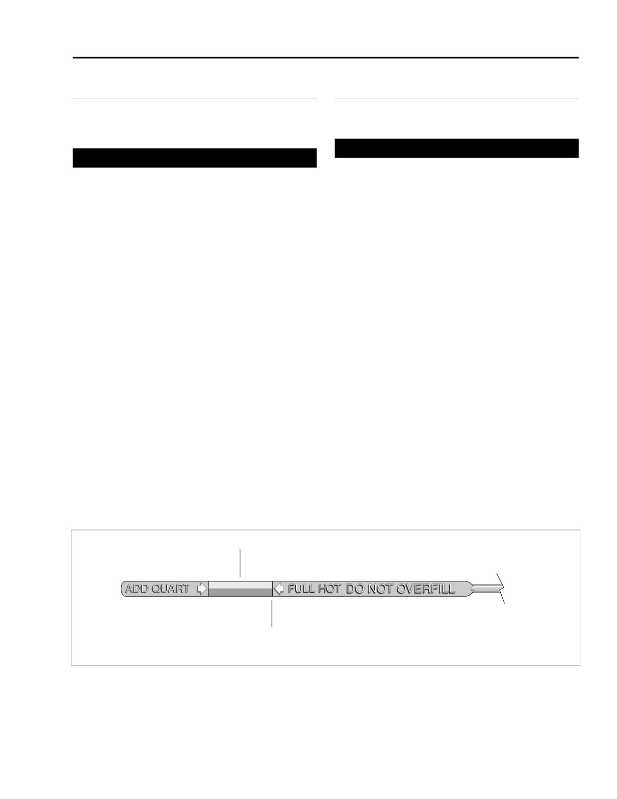
CHECKING ENGINE OIL LEVEL
pump.
CAUTION
CAUTION
Oil level cannot be accurately measured on a cold
Using gasolines with alcohol additives (such as metha-
engine. For preride inspection, with motorcycle leaning
nol) can cause rubber components within the fuel sys-
on jiffy stand on level ground, oil should register on dip-
tem to fail or result in engine damage.
stick between arrows when engine is cold. Do NOT add
oil to bring the level to the FULL mark on a COLD engine.
GASOLINE/ALCOHOL BLENDS
1. Perform engine oil level COLD CHECK as follows:
Harley-Davidson motorcycles were designed to give the best
a. With the vehicle resting on the jiffy stand on level
performance using unleaded gasoline. Some fuel suppliers
ground, wipe off the dipstick and insert it back into
sell gasoline/alcohol blends as a fuel. The type and amount
the oil pan with the plug pushed completely into the
of alcohol added to the fuel is important.
fill spout.
● DO NOT USE GASOLINES CONTAINING METHANOL.
b. Remove the dipstick and note the level of the oil. Oil
Using gasoline/methanol blends will result in starting
level should register between the two arrows on the
and driveablility deterioration and damage to critical fuel
dipstick. See Figure 3-1. If oil level is at or below the
system components.
lower arrow, add only enough oil to bring the level
● ETHANOL is a mixture of 10% ethanol (Grain alcohol)
between the two arrows on the dipstick.
and 90% unleaded gasoline. Gasoline/ethanol blends
2. Perform engine oil level HOT CHECK as follows:
can be used in your motorcycle if the ethanol content
a. Ride vehicle until engine is at normal operating tem-
does not exceed 10%.
perature.
● REFORMULATED OR OXYGENATED GASOLINES
b. With the vehicle resting on the jiffy stand on level
(RFG):
“Reformulated gasoline” is a term used to
ground, allow engine to idle for 1-2 minutes. Turn
describe gasoline blends that are specifically designed
engine off.
to burn cleaner than other types of gasoline. Your motor-
cycle will run normally using this type of gas.
c. Wipe off the dipstick and insert it back into the oil
pan with the plug pushed completely into the fill
You may find that some gasoline blends adversely affect the
spout.
starting, driveability or fuel efficiency of your bike. If you
experience one or more of these problems, we recommend
d. Remove the dipstick and note the level of the oil.
you try a different brand of gasoline or gasoline with a higher
Add only enough oil to bring the level to the FULL
octane rating.
mark on the dipstick. See Figure 3-1. Do not overfill.
COLD CHECK
HOT CHECK
f1254b3x
Figure 3-1. Engine Oil Dipstick
2004 Touring: Engine
3-5
HOME
5.
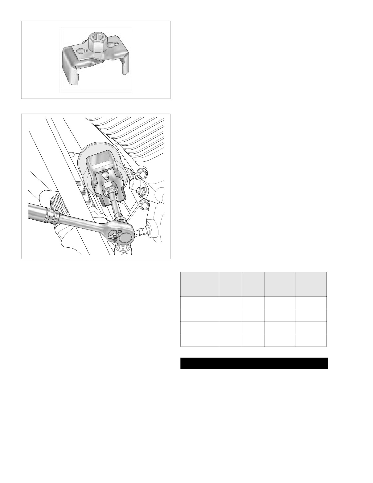
Remove the oil filter as follows:
a. Obtain the OIL FILTER WRENCH (HD-42311). The
tool allows easy removal of the oil filter without risk
of damage to the crankshaft position sensor or
cable.
b. Place the jaws of the wrench over the oil filter with
the tool oriented vertically. See Figure 3-3.
c. Using a 3/8 inch drive with a 4 inch extension, turn
wrench in a counterclockwise direction. Do not use
with air tools.
Figure 3-2. Oil Filter Wrench (Part No. HD-42311)
NOTE
Use OIL FILTER WRENCH (HD-44067) if HD-42311 is not
f1641x3x
available.
6.
Clean the oil filter mount flange of any old gasket mate-
rial.
7.
Lubricate gasket with clean engine oil and install new oil
filter on filter mount. Hand tighten oil filter 1/2-3/4 turn
after gasket first contacts filter mounting surface. Do
NOT use OIL FILTER WRENCH for oil filter installation.
NOTE
Use of the Premium 10 micron synthetic media oil filter is
highly recommended, Part No. 63798-99 (Chrome) or 63731-
99 (Black).
8.
Install engine oil drain plug with O-ring. Tighten plug to
14-21 ft-lbs (19-28 Nm).
9.
With vehicle resting on jiffy stand, add 3-1/2 quarts (3.3
liters) engine oil as specified in Table 3-1. Use the proper
grade of oil for the lowest temperature expected before
the next oil change.
Figure 3-3. Remove Engine Oil Filter
Table 3-1. Recommended Engine Oils
Harley-
Lowest
Cold Weather
CHANGING ENGINE OIL AND FILTER
Harley-Davidson
Viscosity
Davidson
Ambient
Starts Below
Type
Rating
Temperature
50˚F (10˚C)
NOTE
SAE
Below 40˚F
At the 1000 mile (1600 km) service interval, and at every
HD Multi-grade
HD 360
Excellent
10W40
(4˚C)
5000 mile (8000 km) service interval thereafter, change the
SAE
Above 40˚F
engine oil and engine oil filter. If motorcycle is ridden hard,
HD Multi-grade
HD 360
Good
20W50
(4˚C)
under dusty conditions or in cold weather, change engine oil
SAE
Above 60˚F
HD Regular Heavy
HD 360
Poor
and filter more often.
50
(16˚C)
SAE
Above 80˚F
1. Ride vehicle until engine is at normal operating tempera-
HD Extra Heavy
HD 360
Poor
60
(27˚C)
ture.
2. Locate oil filler plug/dipstick on right side of vehicle at top
of transmission case. To remove the oil filler plug, pull
CAUTION
steadily while moving plug back and forth.
Oil level cannot be accurately measured on a cold
3. Locate oil drain plug at front left side of the oil pan.
engine. For preride inspection, with motorcycle leaning
Remove the oil drain plug and allow oil to drain com-
on jiffy stand on level ground, oil should register on dip-
pletely.
stick between arrows when engine is cold. Do NOT add
oil to bring the level to the FULL mark on a COLD engine.
4. Inspect the oil drain plug O-ring for cuts, tears or signs of
deterioration. Replace as necessary.
10. Perform engine oil level COLD CHECK as follows:
3-6
2004 Touring: Engine
HOME
a. With the vehicle resting on the jiffy stand on level
ground, wipe off the dipstick and insert it back into
CAUTION
the oil pan with the plug pushed completely into the
Check the engine oil level if the oil pressure indicator
fill spout.
lamp remains illuminated. If the oil level is normal, stop
b. Remove the dipstick and note the level of the oil. Oil
the engine immediately. Do not ride the vehicle until the
level should register between the two arrows on the
probem is located and corrected.
dipstick. See Figure 3-1. If oil level is at or below the
lower arrow, add only enough oil to bring the level
If the indicator lamp is not extinguished, it may be the result
between the two arrows on the dipstick.
of a low oil level or diluted oil supply. In freezing weather, the
oil feed and return lines can clog with ice or sludge. A defect
11.
Perform engine oil level HOT CHECK as follows:
in the lamp wiring, faulty oil pressure switch/sender, dam-
aged oil pump, plugged oil filter element, incorrect oil viscos-
a. Ride vehicle until engine is at normal operating tem-
ity, broken or weak spring in the oil pressure relief valve and/
perature.
or damaged or incorrectly installed O-rings in the engine may
b. With the vehicle resting on the jiffy stand on level
also cause the indicator lamp to remain on.
ground, allow engine to idle for 1-2 minutes. Turn
To troubleshoot the problem, always check the engine oil
engine off.
level first. If the oil level is OK, determine if oil returns to the
c. Wipe off the dipstick and insert it back into the oil
pan from the oil return hose. If oil does not return, shut off the
pan with the plug pushed completely into the fill
engine until the problem is located and corrected.
spout.
To check the engine oil pressure, proceed as follows:
d. Remove the dipstick and note the level of the oil.
Add only enough oil to bring the level to the FULL
1.
Verify engine oil level. See CHECKING ENGINE OIL
mark on the dipstick. See Figure 3-1. Do not overfill.
LEVEL in this section.
12.
Start engine and carefully check for oil leaks around
2.
Locate the oil pressure switch/sender at the front right
drain plug and oil filter.
side of the crankcase.
3.
On FLHR/C/S models, pull elbow from post of oil pres-
sure switch. On FLHT/C/U and FLTR models, pull exter-
WINTER LUBRICATION
nal latch outward and use rocking motion to remove
Packard connector from oil pressure sender.
Combustion in an engine produces water vapor. During start-
4.
On FLHR/C/S models, use a 15/16 inch Open End Crow
ing and warm-up in cold weather, especially in freezing tem-
peratures, the vapor condenses to water before the
Foot (Snap-On FC30B) to remove oil pressure switch
crankcase is hot enough to exhaust it through the breather
from crankcase. On FLHT/C/U and FLTR models, use 1-
system. If the engine is run long enough for the crankcase to
1/16 inch Open End Crow Foot (Snap-On FC34A) to
become thoroughly heated, the water returns to vapor and is
remove oil pressure sender.
then exhausted.
5.
Start OIL PRESSURE GAUGE ADAPTER (HD-96921-
110) into crankcase bore. Using a 5/8 inch open end
An engine used for only short trips, and seldom allowed to
wrench, turn adapter until snug. See Figure 3-4.
thoroughly warm up, accumulates increasing amounts of
water in the oil pan. Water mixed with oil forms a sludge that
6.
Moving to left side of vehicle, route banjo fitting and hose
causes accelerated engine wear. In freezing temperatures,
of OIL PRESSURE GAUGE
(HD-96921-52B) over
the water becomes slush or ice, which may clog oil lines and
shifter lever and oil filter to right side of engine. See Fig-
result in engine failure.
ure 3-5.
Always change the engine oil more often in winter. If the
7.
Slide washer on banjo bolt and insert through banjo fit-
engine is used for short runs, change the oil even more fre-
ting on gauge. Install second washer on bolt and thread
quently. The farther below freezing the temperature drops the
into adapter until snug.
more often the oil should be changed.
8.
Run vehicle or simulate road running until engine is at
normal operating temperature, approximately
230o F.
(110o C.). Gauge reading will not be accurate if engine is
OIL PRESSURE INDICATOR LAMP
not completely warmed.
9.
Verify that oil pressure is 30-38 psi (207-262 kN/m2) at
The red OIL PRESSURE indicator lamp illuminates to indi-
2000 rpm.
cate improper circulation of the engine oil. The lamp illumi-
nates when the ignition is first turned on (before the engine is
10.
Remove banjo bolt (and washers) from adapter. Remove
started), but should be extinguished once the engine is run-
gauge from vehicle and then remove adapter from
ning.
crankcase.
2004 Touring: Engine
3-7