Harley Davidson 2004 Touring Models. Service Manual - page 35
HOME
5.
Push passenger seat forward until rear fender seat
retention nut is centered in hole of rear mounting
f1550x2x
bracket. Install Phillips screw.
Slot
NOTE
If seat retention nut is damaged or lost, see SEAT RETEN-
TION NUT REPLACEMENT for instructions.
1WARNING
Pull up on seat to verify that it is properly secured, front
and rear. A loose seat may shift during vehicle operation
and startle the rider, possibly causing loss of vehicle
control resulting in death or serious injury.
FLHRC
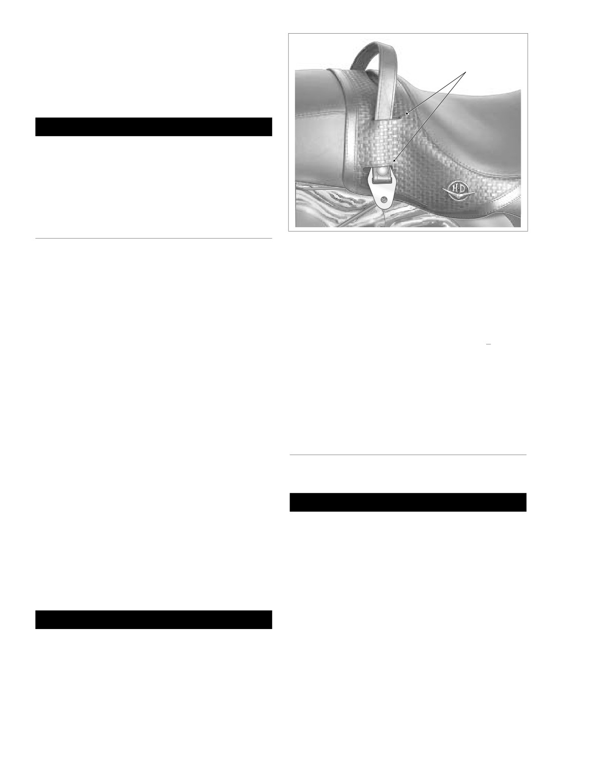
Figure 2-128. Route Passenger Seat Strap Through
Slots in Seat - FLHRC
REMOVAL
1.
Remove right side saddlebag. See Section 2.25 SAD-
4. Using slots in seat, route free end of passenger seat
DLEBAG, REMOVAL.
strap to right side of vehicle. See Figure 2-128.
2.
Remove bolt (with flat washer) to remove passenger
5. Insert bolt with flat washer through passenger seat strap
seat strap and saddlebag front mounting bracket from
and slotted hole of saddlebag front mounting bracket.
chrome frame tube cover.
Insert bolt into forward hole in chrome frame tube cover.
3.
Using slots in seat, carefully pull passenger seat strap
Snug saddlebag front mounting bracket bolt, but do not
from seat. See Figure 2-128.
tighten.
6.
Install right side saddlebag. See Section 2.25 SADDLE-
4.
Remove Phillips screw to detach seat mounting bracket
BAG, INSTALLATION.
from top of rear fender.
7.
Using an open end/box wrench, tighten saddlebag front
5.
Push seat rearward to free tongue at front of seat from
mounting bracket bolt.
slot in frame backbone. See Figure 2-127.
6.
Remove seat from frame.
FLHRS, FLTR
INSTALLATION
1.
Place seat on frame backbone.
REMOVAL
2.
Firmly push front of seat downward and rearward until
tongue engages slot in frame backbone. See Figure 2-
CAUTION
127.
Removing seat without first removing passenger seat
3.
Push seat forward until rear fender seat retention nut is
strap will result in damage to rear fender paint.
centered in hole of mounting bracket. Install Phillips
screw.
1.
Remove right side saddlebag. See Section 2.25 SAD-
DLEBAG, REMOVAL.
NOTE
2.
Remove bolt (with flat washer) to remove passenger
If seat retention nut is damaged or lost, see SEAT RETEN-
seat strap and saddlebag front mounting bracket from
TION NUT REPLACEMENT for instructions.
chrome frame tube cover. Draw free end of passenger
seat strap to left side of vehicle.
3.
Remove Phillips screw to detach seat mounting bracket
1WARNING
from top of rear fender.
Pull up on seat to verify that it is properly secured, front
4.
Push seat rearward to free tongue at front of seat from
and rear. A loose seat may shift during vehicle operation
slot in frame backbone. See Figure 2-127.
and startle the rider, possibly causing loss of vehicle
5.
Remove seat from frame.
control resulting in death or serious injury.
2-102
2004 Touring: Chassis
HOME
INSTALLATION
1
WARNING
1. Place seat on frame backbone.
Pull up on seat to verify that it is properly secured, front
2. Firmly push front of seat downward and rearward until
and rear. A loose seat may shift during vehicle operation
tongue engages slot in frame backbone. See Figure 2-
and startle the rider, possibly causing loss of vehicle
127.
control resulting in death or serious injury.
3. Push seat forward until rear fender seat retention nut is
centered in hole of mounting bracket. Install Phillips
screw.
NOTE
FLHTC/U
If seat retention nut is damaged or lost, see SEAT RETEN-
TION NUT REPLACEMENT for instructions.
REMOVAL
1WARNING
1.
Open Tour-Pak to move passenger seat backrest out of
the way.
Pull up on seat to verify that it is properly secured, front
and rear. A loose seat may shift during vehicle operation
NOTE
and startle the rider, possibly causing loss of vehicle
The Tour-Pak must be positioned to the rear to access the
control resulting in death or serious injury.
seat mounting bracket screw. If the Tour-Pak is in the forward
4.
Draw free end of passenger seat strap to right side of
position, remove Tour-Pak and install in rearward position.
vehicle. Insert bolt with flat washer through passenger
See Section 2.26 TOUR-PAK for more information.
seat strap and slotted hole of saddlebag front mounting
bracket. Insert bolt into forward hole in chrome frame
2.
Remove Phillips screw to detach seat mounting bracket
tube cover. Snug saddlebag front mounting bracket bolt,
from top of rear fender.
but do not tighten.
3.
To protect finish of Tour-Pak, cover rear seat mounting
5. Install right side saddlebag. See Section 2.25 SADDLE-
bracket with palm of hand.
BAG, INSTALLATION.
4.
While pushing seat forward, raise rear of seat until
6. Using an open end/box wrench, tighten saddlebag front
bracket clears top of Tour-Pak. Push seat rearward
mounting bracket bolt.
slightly to free tongue at front of seat from slot in frame
backbone. See Figure 2-127.
5.
Remove seat from frame.
FLHT
INSTALLATION
REMOVAL
1.
Place seat on frame backbone.
1. Remove Phillips screw to detach seat mounting bracket
2.
To protect finish of Tour-Pak, cover rear seat mounting
from top of rear fender.
bracket with palm of hand.
2. Push seat rearward to free tongue at front of seat from
3.
While raising rear of seat approximately 3 inches (76.2
slot in frame backbone. See Figure 2-127.
mm), use other hand to firmly push front of seat down-
3. Remove seat from frame.
ward and rearward until tongue engages slot in frame
backbone. See Figure 2-127.
4.
Push seat forward until rear fender seat retention nut is
INSTALLATION
centered in hole of mounting bracket. Install Phillips
screw.
1. Place seat on frame backbone.
NOTE
2. Firmly push front of seat downward and rearward until
tongue engages slot in frame backbone. See Figure 2-
If seat retention nut is damaged or lost, see SEAT RETEN-
127.
TION NUT REPLACEMENT for instructions.
3. Push seat forward until rear fender seat retention nut is
centered in hole of mounting bracket. Install Phillips
1WARNING
screw.
Pull up on seat to verify that it is properly secured, front
NOTE
and rear. A loose seat may shift during vehicle operation
If seat retention nut is damaged or lost, see SEAT RETEN-
and startle the rider, possibly causing loss of vehicle
TION NUT REPLACEMENT for instructions.
control resulting in death or serious injury.
2004 Touring: Chassis
2-103
HOME
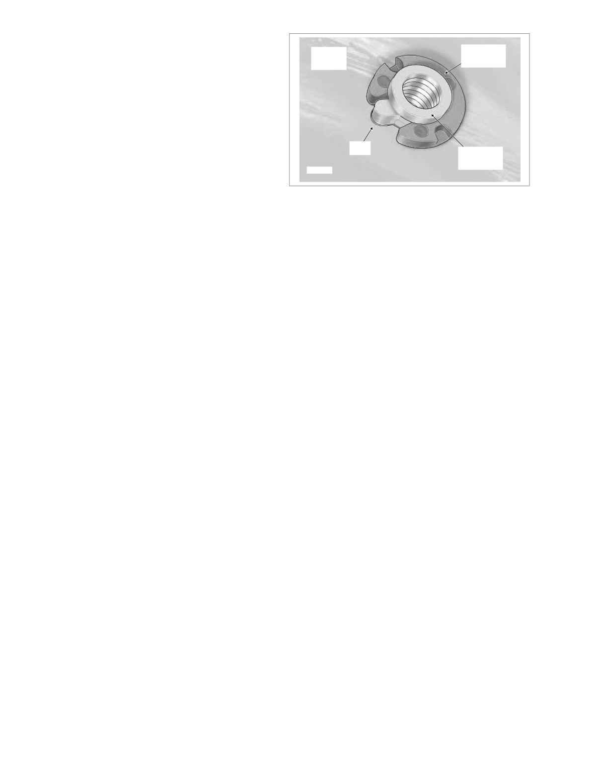
SEAT RETENTION NUT REPLACEMENT
Rear
Retention
1.
Slide retention nut over tapered end of cable strap so
Washer
Fender
that larger OD of nut rests on cable strap eyelet. From
bottom of rear fender, feed cable strap up through fender
hole.
2.
See Figure 2-129. With tab on retention nut seated in
notch of fender hole, pull up on cable strap to hold nut
snug against underside of rear fender. From the side
Tab
opposite the tab, slide on the retention washer to lock
Retention
the position of the retention nut. Remove cable strap.
Nut
f1897x2x
Figure 2-129. Seat Retention Nut and Washer
2-104
2004 Touring: Chassis
HOME
SADDLEBAG
2.25
OPENING
NOTE
Maximum recommended load for each saddlebag is 15 lbs.
FLHRC
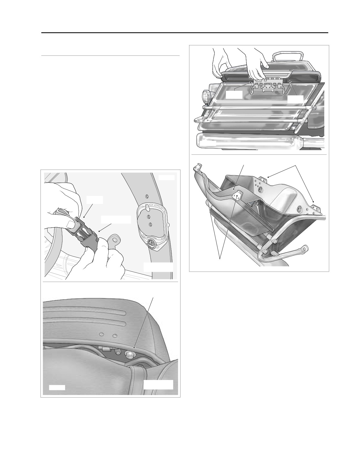
1. Raise the decorative buckle and press tabs on both
Hinge
sides of catch to release from receptacle. Repeat step to
Latch
release second catch. See upper frame of Figure 2-130.
2. Rotate hinge on outboard side of saddlebag to open lid.
FLHRS
1. Depress button on front inboard side of saddlebag, and
f1554x2x
while holding button in, raise lid. See lower frame of Fig-
ure 2-130.
Check Strap
Anchor Brackets
f1552x2x
Catch
Receptacle
Anchor Tabs
f1553x2x
FLHRC
Figure 2-131. Open Saddlebag (FLHR, FLTR, FLHT/C/U)
Button
2.
Rotate hinge on inboard side of saddlebag to open lid.
FLHR, FLTR, FLHT/C/U
1.
Use key to unlock lid latch if locked.
2.
Pull bottom of latch outward and then lift upward raising
outboard corners of saddlebag lid. See upper frame of
Figure 2-131.
3.
With top of lid tilted toward motorcycle, carefully lift
inboard side of lid upward disengaging front and rear
anchor tabs from anchor brackets.
4.
Pivot lid on latch hinge to open. A nylon check strap sus-
FLHRS
f2228x3x
pends the lid in the open position. See lower frame of
Figure 2-131.
Figure 2-130. Open Saddlebag (FLHRC/S)
2004 Touring: Chassis
2-105
HOME
f1451x2x
Front Mounting
Front
Bracket Bolt
Rear
Mounting
Mounting
Bracket
Bracket
Quick-Release
Stud
Wire
Form
Spring
Flat
Plate
Washer
Bail
Wire
f1075axx
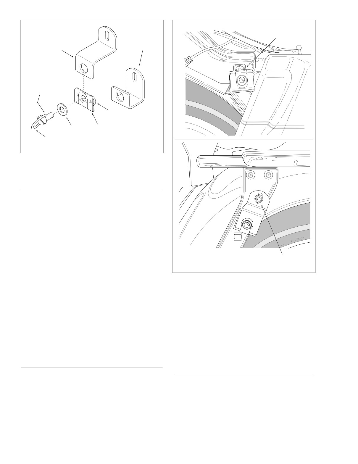
Figure 2-132. Saddlebag Quick-Release Fasteners
CLOSING
FLHRC
1. Rotate hinge on outboard side of saddlebag to close lid.
2.
Insert catch into receptacle until tabs fully engage.
Repeat step to secure second catch. See upper frame of
Figure 2-130.
FLHRS
Rear Mounting
f1450x2x
Bracket Bolt
1.
Rotate hinge on inboard side of saddlebag to close lid.
Lid latches automatically.
Figure 2-133. Saddlebag Mounting Bracket Bolts
(Right Side View)
FLHR, FLTR, FLHT/C/U
1.
Rotate lid to closed position engaging both anchor tabs
NOTE
with bottom of anchor brackets. Press bottom of latch
On some HDI vehicles, the bail wire has been removed from
inward until it snaps closed. See lower frame of Figure 2-
the quick release stud. In these cases, turn the stud by
131.
engaging the slotted end with a large screwdriver.
2.
Use key to lock lid latch.
3. Remove saddlebag.
REMOVAL
INSTALLATION
1.
Open saddlebag. See OPENING in this section.
2.
Grasp bail wire inside saddlebag and rotate each stud a
1.
Position saddlebag on vehicle.
full
1/4 turn in a counter-clockwise direction. Remove
2.
Place flat washers on bail head studs.
bail head studs with flat washers. See Figure 2-132.
2-106
2004 Touring: Chassis
HOME
3. With groove at end of stud held in a horizontal position,
insert stud through holes in saddlebag and front mount-
Rub Bar
ing bracket. When groove engages wire form of spring
plate on inboard side of bracket, turn stud clockwise a
full 1/4 turn until it snaps in place. Install rear bail head
stud in the same manner.
NOTE
On some HDI vehicles, the bail wire has been removed from
the quick release stud. In these cases, turn the stud by
engaging the slotted end with a large screwdriver.
NOTE
8862
Molded rubber insert at bottom of saddlebag must fit snugly
on lower saddlebag support rail. If saddlebag is not fully
seated, use an open end/box wrench to loosen bolts secur-
ing mounting brackets to saddlebag support and frame. See
Figure 2-133. Alternately tighten bolts to 60-96 in-lbs (7-11
Nm) after seating saddlebag.
4. Close saddlebag. See CLOSING in this section.
LATCH SPRING REPLACEMENT
(FLHR, FLTR, FLHT/C/U)
8863
REMOVAL
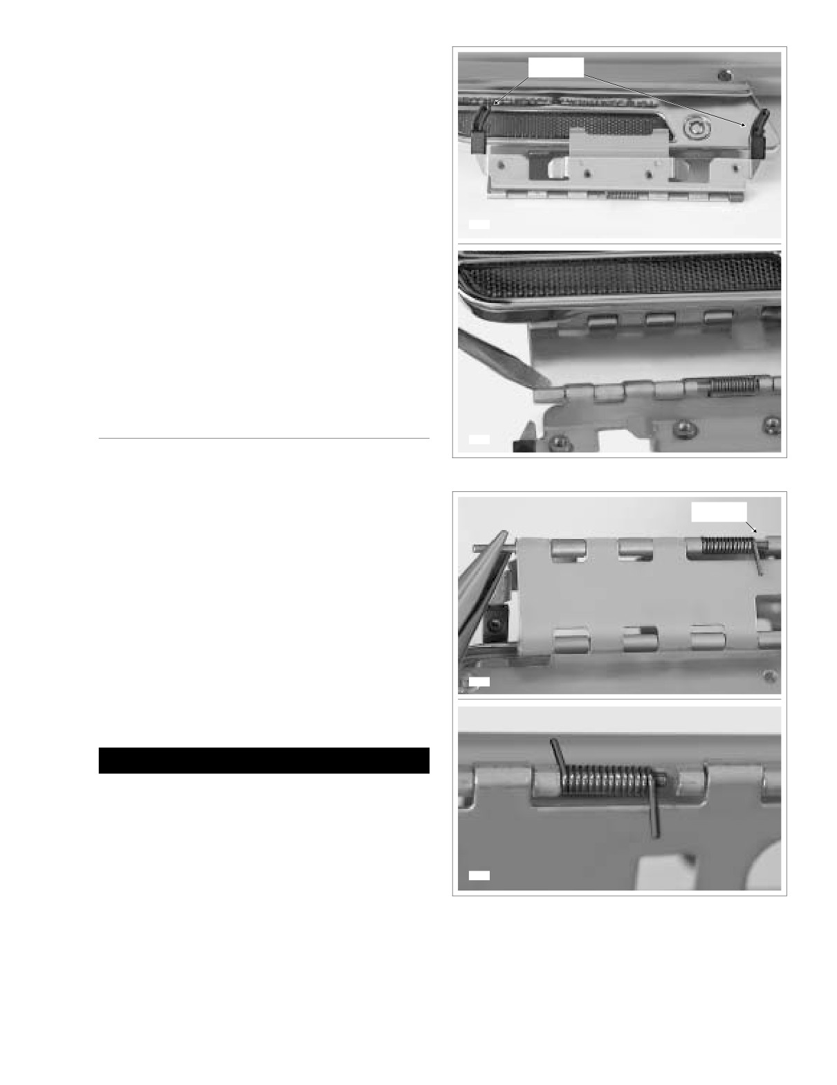
Figure 2-134. Lid Right Side Up With Latch on Near Side
1. Lay clean pad or blanket on work bench to protect
painted surfaces of saddlebag.
Opening
2. Remove saddlebag from motorcycle leaving lid open.
See REMOVAL in this section.
3. Lay saddlebag flat on pad with the inboard side facing
up and the lid closest to you.
4. Remove two T20 TORX screws to release check strap
from lid.
5. Remove two T15 TORX screws to release check strap
from saddlebag.
8864
6. Remove two remaining T15 TORX screws to remove
latch from saddlebag. Move saddlebag back and out of
the way.
CAUTION
This procedure assumes that the latch is NOT removed
from the saddlebag lid. If there is doubt as to whether the
procedure can be accomplished without scratching
painted surfaces of the lid, then remove the five remain-
ing T15 TORX screws to completely remove latch.
7. Position lid right side up with latch closest to you.
8865
8.
Raise latch slightly and rotate hinge on inboard side so
Figure 2-135. Lid Up Side Down With Latch on Far Side
that it is topside with the two plastic rub bars pointed
upward. See upper frame of Figure 2-134.
2004 Touring: Chassis
2-107
HOME
9.
Rotate rub bar section of hinge to expose hinge pin and
CABLE ASSEMBLY/LATCH/SCRIPT
spring. Using a flat tip screwdriver, carefully bend
crimped end link outward. See lower frame of Figure 2-
(FLHRS)
134.
NOTE
CABLE ASSEMBLY
The end link on opposite side of hinge has a weld spot that
prevents pin removal.
Removal
10. Reposition lid so that it is upside down with the latch
1.
Open saddlebag. See OPENING in this section.
farthest from you. Rotate hinge so that plastic rub bars
are positioned beneath latch and spring is topside.
2.
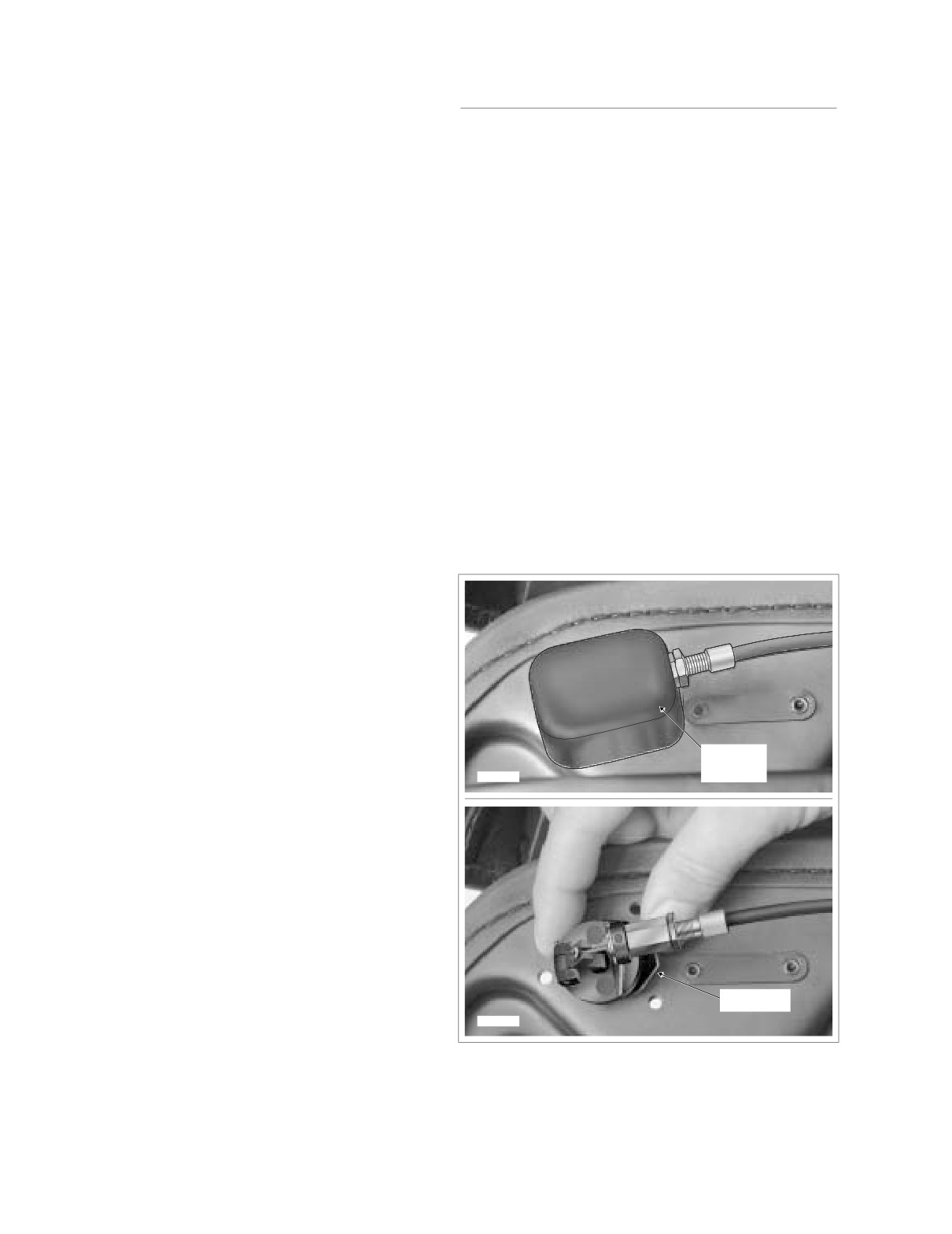
Remove two screws on inboard side of saddlebag to
11. Using a needle nose pliers, grasp pin through opening
release plastic shroud. See upper frame of Figure 2-136.
just outboard of the spring and push toward the crimped
3.
Depress wireform and pull button from hole in saddle-
link side. Work pin in this manner until end can be seen
bag. See lower frame of Figure 2-136.
exiting crimped link. See upper frame of Figure 2-135. If
necessary, pry crimped link outward a little more to
4.
Remove sleeve from hole in saddlebag.
achieve the desired result.
5.
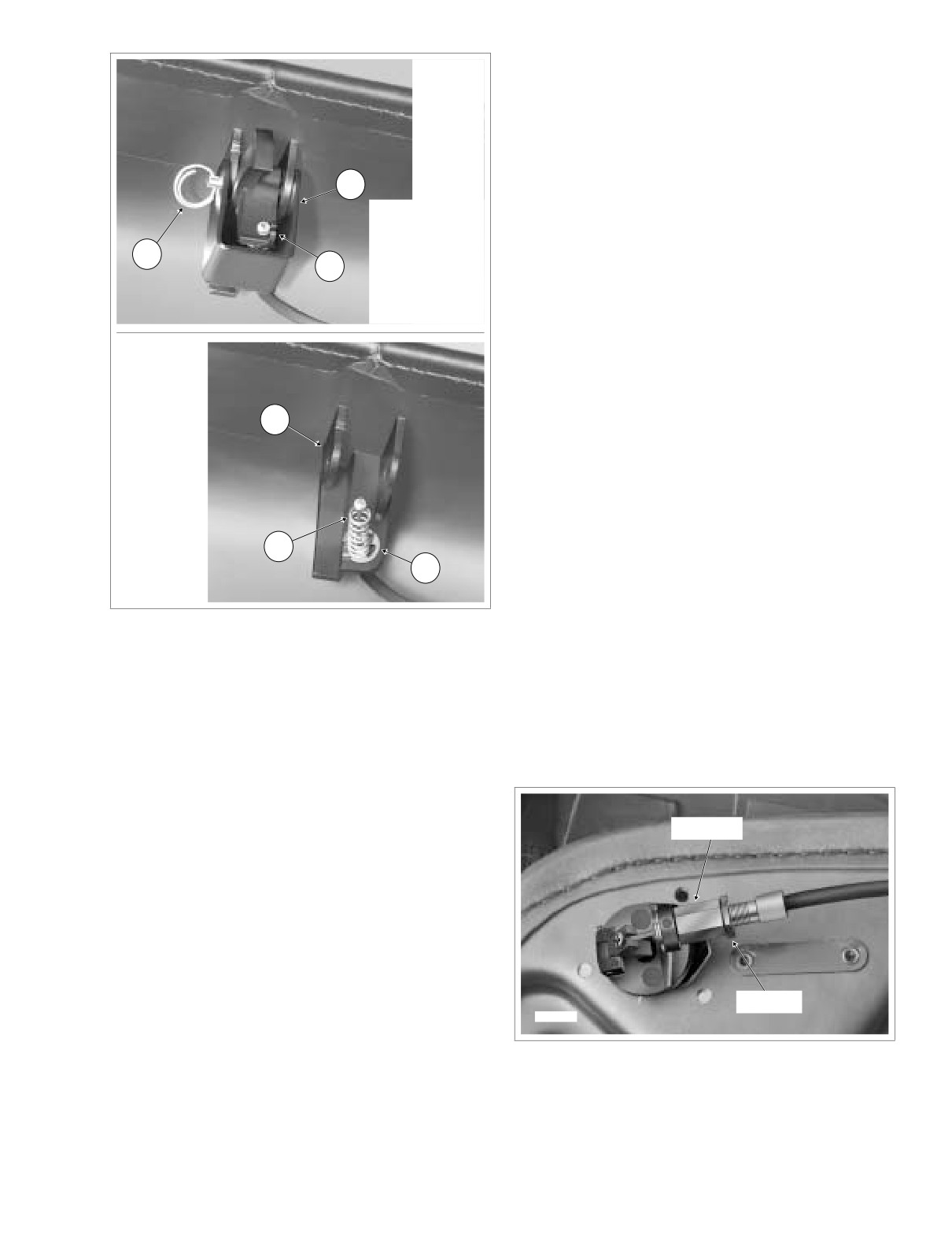
Moving to inboard side of saddlebag lid, remove lock
12. Grasping end with needle nose pliers, slowly pull pin
ring from hole at end of latch pin. See upper frame of
from links until spring can be slid off opposite end. Only
Figure 2-137.
pull pin as far as necessary to remove spring. See lower
frame of Figure 2-135.
6.
Pull latch pin from metal shroud, saddlebag bracket and
latch. Remove metal shroud.
INSTALLATION
7.
Depress spring and pull on cable ball end to remove
from slot in latch. Remove latch.
1.
Slide new spring onto end of pin. Orient spring as shown
in lower frame of Figure 2-135.
8.
Remove spring from cable. See lower frame of Figure 2-
137.
2.
Slide pin back through links. Using tapered end of
needle nose pliers, push end of pin into crimped link
3.
Reposition lid so that it is right side up with latch closest
to you. As before, raise latch slightly and rotate hinge on
inboard side so that it is topside with plastic rub bars
pointing upward. Now rotate rub bar section of hinge to
expose hinge pin and spring. See Figure 2-134.
4.
Holding lid down with elbow, if necessary, use a pliers to
bend crimped link back into its original position, so that
pin is captured and will not back out of hinge.
5.
Reposition lid so that it is upside down with the latch
farthest from you. Move saddlebag forward for
Plastic
Shroud
reinstallation of lid. Align four holes in saddlebag with
f2229x2x
those in latch.
6.
Install two inboard T15 TORX screws to fasten latch to
saddlebag. Alternately tighten screws to 20-25 in-lbs
(2.3-2.8 Nm).
7.
Align holes in check strap with those in lid and
saddlebag. Orient check strap so that logo is topside
with the bottom of the bar and shield on the lid side.
8.
Install two T15 TORX screws to fasten check strap and
latch to saddlebag. Alternately tighten screws to 20-25
in-lbs (2.3-2.8 Nm).
9.
Install two T20 TORX screws to fasten check strap to lid.
Wireform
Alternately tighten screws to 18-20 in-lbs (2.0-2.3 Nm).
f2232x2x
10.
Close saddlebag and install on motorcycle. See
Figure 2-136. Remove Button Assembly
INSTALLATION in this section.
2-108
2004 Touring: Chassis
HOME
5.
Install cable end fitting into hole in saddlebag bracket.
f2233x2x
6.
With the rounded edge of the e-clip on the same side as
the rounded edge of the saddlebag bracket, install e-clip
into groove in cable end fitting.
7.
Pull up on cable ball end and install spring on cable. See
lower frame of Figure 2-137.
2
NOTE
1.
Lock Ring
2.
Metal Shroud
Verify that ball end on opposite side of cable is installed in
3.
Latch Slot
pivot of button assembly. See Figure 2-138.
1
4.
Saddlebag
3
Bracket
8.
Position latch between saddlebag bracket with the cable
5.
Spring
slot inline with the cable ball end. Depress spring and
6.
E-Clip
capture cable ball end in slot of latch.
9.
Install metal shroud over latch and saddlebag bracket. At
rear of assembly, insert latch pin through metal shroud,
saddlebag bracket and latch until end exits front hole in
shroud.
4
10. Install lock ring into hole at end of latch pin. See upper
frame of Figure 2-137.
11. Close and open saddlebag lid several times to verify that
latch locks every time. Adjust cable if necessary.
Adjustment
5
1.
Open saddlebag. See OPENING in this section.
6
f2234x2x
2.
Remove two screws on inboard side of saddlebag to
release plastic shroud. See upper frame of Figure 2-136.
Figure 2-137. Remove Latch Assembly
3.
Back jam nut away from body hex. See Figure 2-138.
4.
Turn body hex toward or away from jam nut until closest
9. Remove e-clip from groove in cable end fitting.
part of latch is approximately 3/8 inch (9.5 mm) from
inboard side of saddlebag lid.
10. Pull cable end fitting from hole in saddlebag bracket.
5.
Turn jam nut until it makes firm contact with body hex.
11. Release cable from channel running along inboard edge
of saddlebag.
Installation
Body Hex
1. From the outboard side, insert sleeve into hole in saddle-
bag.
2. On the inboard side, depress wireform and slide button
into sleeve. Release wireform. Gently tug on assembly
to verify that wireform has engaged groove in sleeve to
lock button in place. See lower frame of Figure 2-136.
3. Holding plastic shroud with the relief positioned over the
cable adjuster, install two screws from inboard side of
Jam Nut
saddlebag. See upper frame of Figure 2-136.
f2235x2x
4. Capture cable in channel running along inboard edge of
saddlebag.
Figure 2-138. Cable Adjustment
2004 Touring: Chassis
2-109
HOME
6.
Holding plastic shroud with the relief positioned over the
cable adjuster, install two screws from inboard side of
CAUTION
saddlebag. See upper frame of Figure 2-136.
Always install push nuts on the end studs first. If center
7.
Close and open saddlebag lid several times to verify that
stud is not done last, end stud can sometimes come out
latch locks every time. Readjust if necessary.
of saddlebag hole during installation of the second push
nut. If this occurs, forcing the last stud in can bend stud
or script and enlarge saddlebag hole.
LATCH
2.
From inside saddlebag, install new push nuts onto
studs. For best results, install push nuts on the end
Removal
studs first.
1.
Open saddlebag. See OPENING in this section.
3.
Close saddlebag. See CLOSING in this section.
2.
Moving to inboard side of saddlebag lid, remove lock
ring from hole at end of latch pin. See upper frame of
Figure 2-137.
3.
Pull latch pin from metal shroud, saddlebag bracket and
SADDLEBAG GUARD/SUPPORT
latch. Remove metal shroud.
RAIL
4.
Depress spring and pull on cable ball end to remove
from slot in latch. Remove latch.
REMOVAL
Installation
1.
Remove saddlebag from motorcycle. See REMOVAL in
1.
Position new latch between saddlebag bracket with the
this section.
cable slot inline with the cable ball end. Depress spring
and capture cable ball end in slot of latch.
2.
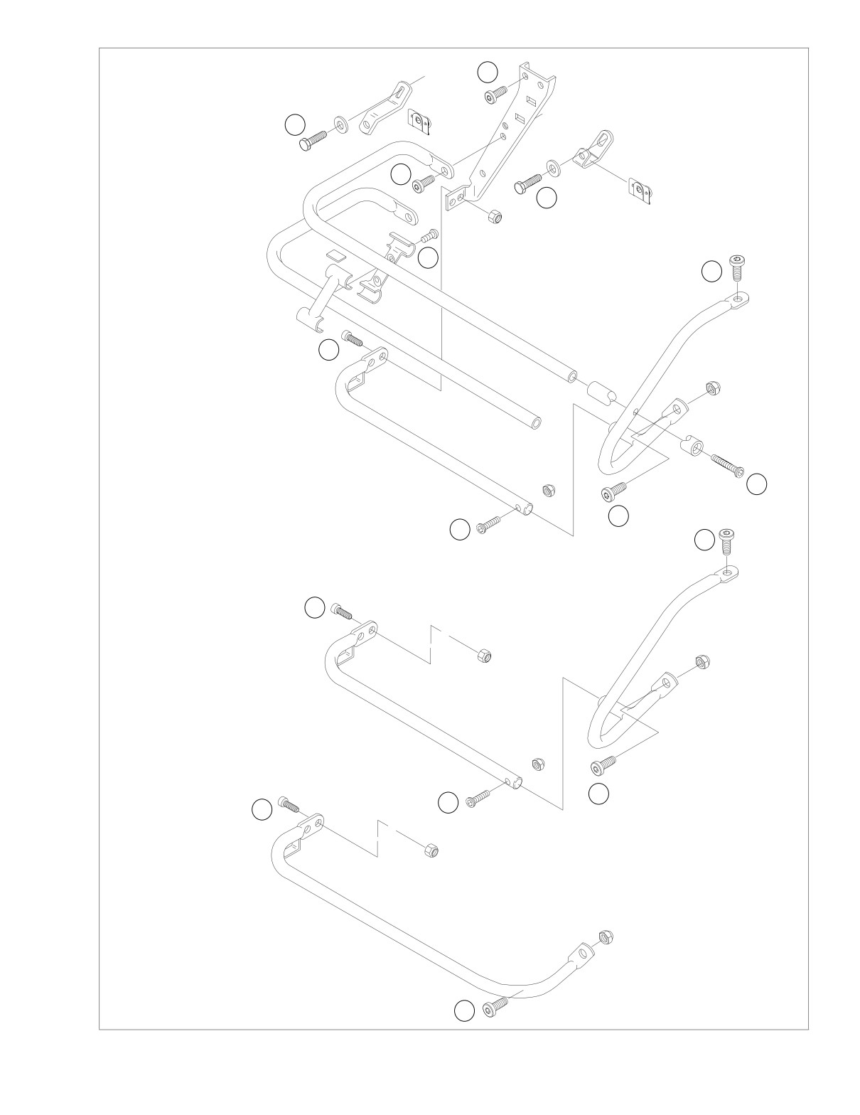
Disassemble saddlebag guard, support and/or rails as
necessary. See Figure 2-139.
2.
Install metal shroud over latch and saddlebag bracket. At
rear of assembly, insert latch pin through metal shroud,
saddlebag bracket and latch until end exits front hole in
INSTALLATION
shroud.
3.
Install lock ring into hole at end of latch pin. See upper
1.
Assemble saddlebag guard, support and/or rails as nec-
frame of Figure 2-137.
essary. Replace any damaged parts. See Figure 2-139.
4.
Close saddlebag. See CLOSING in this section.
2.
Install saddlebag on motorcycle. See INSTALLATION in
this section.
SCRIPT
Removal
1.
Open saddlebag. See OPENING in this section.
CAUTION
Do not remove push nuts unless script replacement is
necessary. Push nuts are damaged during removal and
studs on script may be bent or broken.
2.
From inside saddlebag, pry push nuts from studs. Dis-
card push nuts.
3.
Remove script from side of saddlebag.
Installation
1.
Install new script on side of saddlebag inserting studs
through holes.
2-110
2004 Touring: Chassis
HOME
2
1
3
1
7
4
FLHTC/U
Multi-Rail
Saddlebag Guard
3
f2247x2x
Torque:
6
1. Saddlebag mounting bracket screws: 60-96 in-lbs (7-11 Nm)
2. Saddlebag support to fender screws: 15-20 ft-lbs (20-27 Nm)
3. Rail to saddlebag support screws: 15-20 ft-lbs (20-27 Nm)
4
4. Guard/support rail to frame screws: 15-20 ft-lbs (20-27 Nm)
5
4
5. Support rail to guard screw: 70-100 in-lbs (8-11 Nm)
6. Guard mount to rail screws: 72-120 in-lbs (8-14 Nm)
7. Rail clamp screws: 30-50 in-lbs (3-6 Nm)
3
Saddlebag Guard
FLHT, FLHR/C
f2248x2x
4
5
3
FLTR, FLHRS
Saddlebag Support Rail
f2249x2x
4
Figure 2-139. Saddlebag Guards/Support Rail
2004 Touring: Chassis
2-111
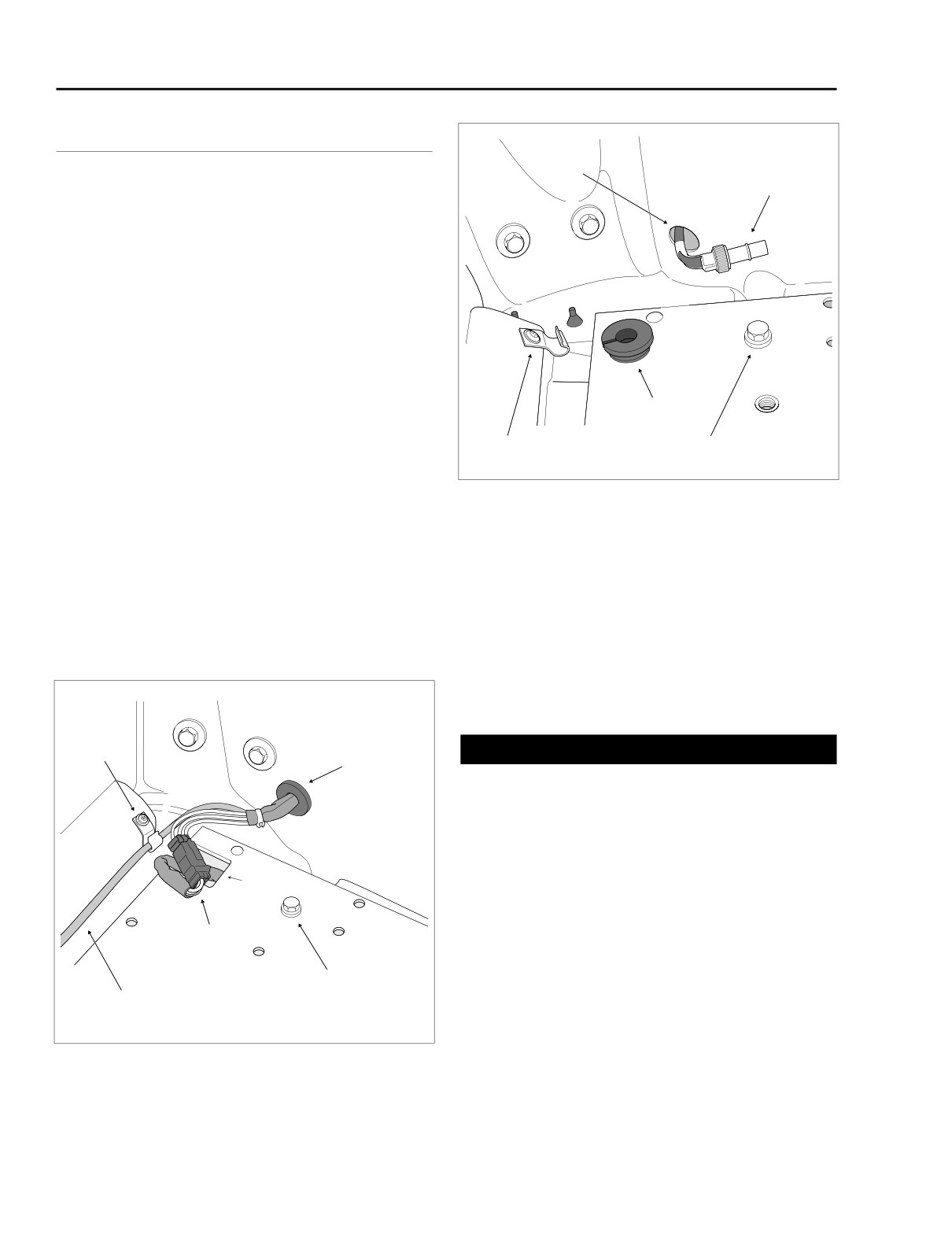
HOME
TOUR-PAK
2.26
FLHTC
Tour-Pak
Hole
Radio Antenna
NOTE
Cable Connector
For instructions covering riveted components, such as hinges
and catches, refer to the Instruction Sheet included with the
RIVET TOOL, HD-39787.
REMOVAL
1.
Open Tour-Pak. Remove rubber mat.
2.
Rotate knurled lock ring in a counter-clockwise direction
to separate pin and socket halves of Radio antenna
cable connector. Release cable from two clips at bottom
of Tour-Pak.
3.
Pull Tour-Pak lights connector [12], 3-place Multilock,
Grommet
from cavity inside Tour-Pak. Depress button and sepa-
rate pin and socket halves. See Figure 2-140.
Cable
Tour-Pak
Clip
Mounting Bolt
4.
Pull grommet into Tour-Pak and remove from main har-
ness conduit.
Figure 2-141. Feed Main Harness Thru Tour-Pak Hole
5.
Feed main harness conduit and connectors through hole
in Tour-Pak. See Figure 2-141.
INSTALLATION
6.
Holding nylon cap locknuts at bottom of Tour-Pak,
remove five bolts (with flat washers) to release Tour-Pak
1.
Place Tour-Pak on luggage rack and open lid.
from luggage rack. Luggage rack spacers will become
free as nuts are removed. Be sure to have a firm grasp
2.
Align rear center hole in Tour-Pak with same hole in lug-
on the Tour-Pak as the last bolt is removed. See Figure
gage rack. Slide 2 inch bolt (with flat washer) through
2-142.
ring terminal of radio antenna ground, and then through
Tour-Pak and luggage rack holes. At bottom of luggage
rack, install spacer (concave side up) and nylon cap
locknut on bolt. With concavity on spacer inline with the
rail, hold nut and tighten bolt until snug.
f1466a2x
Cable
Clip
CAUTION
Grommet
Always install the mounting bolts from inside the Tour-
Pak. If the bolts are installed upside down, then the ends
of the bolts can tear the molded liner and scratch
objects, such as helmets, stored inside the Tour-Pak.
3.
Install remaining
2 inch bolts (with flat washers and
nylon cap locknuts) in two front Tour-Pak and luggage
Cavity
rack holes (one each side) in the manner described
under step 2 above.
Tour-Pak Lights
4.
Position two spacers between bottom of luggage rack
Connector [12]
and tabs of license plate bracket. Slide 2-1/4 inch bolts
(with flat washers) through two center holes in Tour-Pak
Tour-Pak
and luggage rack, and then through spacers and tabs of
Radio Antenna
Mounting Bolt
license plate bracket. If necessary, loosen two hex bolts
Cable
at back of license plate bracket to align holes in tabs with
bolts. Install flat washers and nylon cap locknuts on bolts
Figure 2-140.
Disconnect Tour-Pak Lights Connector
and tighten until snug. See inset of Figure 2-142.
2-112
2004 Touring: Chassis
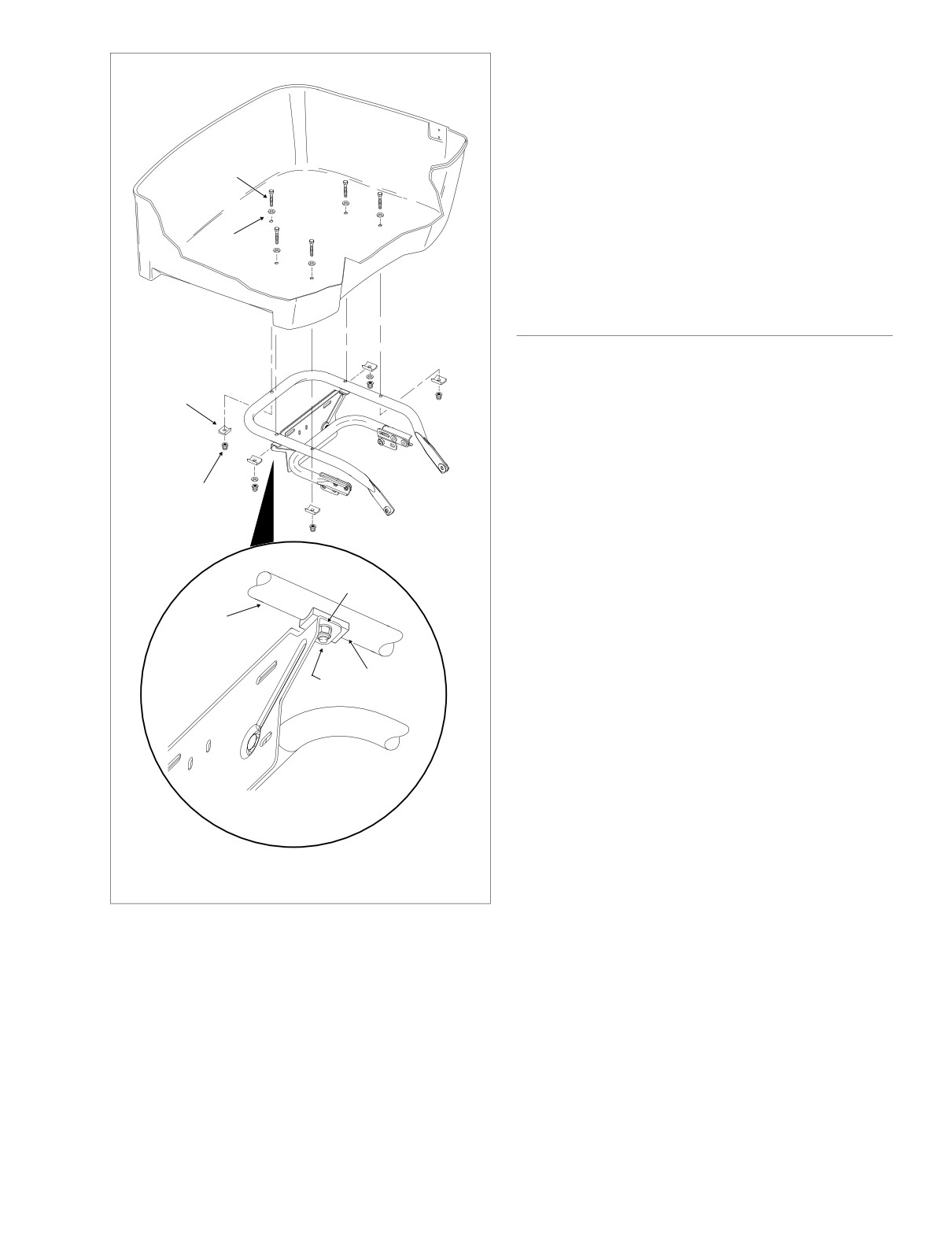
HOME
6.
Standing on left side of vehicle, feed socket connectors
and main harness conduit through hole in Tour-pak.
f1850x2x
Capture conduit in grommet. Install grommet in hole with
the larger OD facing inside.
7.
Mate pin and socket halves of Tour-pak lights connector
Rear Center Hole
Mounting Bolt
[12], 3-place Multilock, and tuck into cavity inside Tour-
(Cap side Up)
Pak. See Figure 2-140.
8.
Rotate knurled lock ring in a clockwise direction to mate
pin and socket halves of Radio antenna cable con-nec-
Flat
tor. Capture cable in two clips at bottom of Tour-Pak.
Washer
9.
Install rubber mat. Close Tour-Pak.
FLHTCU
REMOVAL
Spacer
1.
Open Tour-Pak. Open map pocket and remove acorn
nuts
(with flat washers). Remove map pocket and
molded liner from Tour-Pak.
2.
Depress external latch and rotate housing to release
Nylon Cap
bulb socket from left side of Tour-Pak.
Locknut
3.
Rotate knurled lock ring in a counterclockwise direction
to separate pin and socket halves of Radio antenna
cable connector. Release cable from two clips at bottom
Flat
of Tour-Pak.
Washer
4.
Pull Tour-Pak lights connector [12], 3-place Multilock,
Luggage
from cavity inside Tour-Pak. Depress button and sepa-
Rack Rail
rate pin and socket halves. See Figure 2-140.
5.
Pull grommet into Tour-Pak and remove from main har-
Spacer
ness conduit.
Nylon Cap
Locknut
6.
Feed main harness conduit and connectors through hole
in Tour-Pak. See Figure 2-141.
7.
Release rear headset receptacle from bracket at bottom
of left side speaker box.
8.
Remove trim ring and gently pull on wire harness to
draw 6-place Mini-Deutsch connector out of left side
speaker box. Depress external latch and use a rocking
motion to separate pin and socket halves.
f1851x2x
Stackup at License Plate Bracket
9.
Moving to right side of vehicle, disconnect 1-place CB
antenna cable connector. Release cable from two clips
Figure 2-142. Install Tour-Pak Mounting Bolts
at bottom of Tour-Pak. See Figure 2-143.
10.
Pull right side grommet into Tour-Pak and remove from
CB antenna cable. Feed CB antenna cable through hole
in Tour-Pak.
5.
In a crosswise pattern, alternately tighten five bolts to
11.
Remove trim ring and gently pull on wire harness to
96-120 in-lbs (10.8-13.5 Nm). Be sure that concavity on
draw 6-place Mini-Deutsch connector out of right side
each spacer is inline with the rail and has not rotated out
speaker box. Depress external latch and use a rocking
of position.
motion to separate pin and socket halves.
2004 Touring: Chassis
2-113
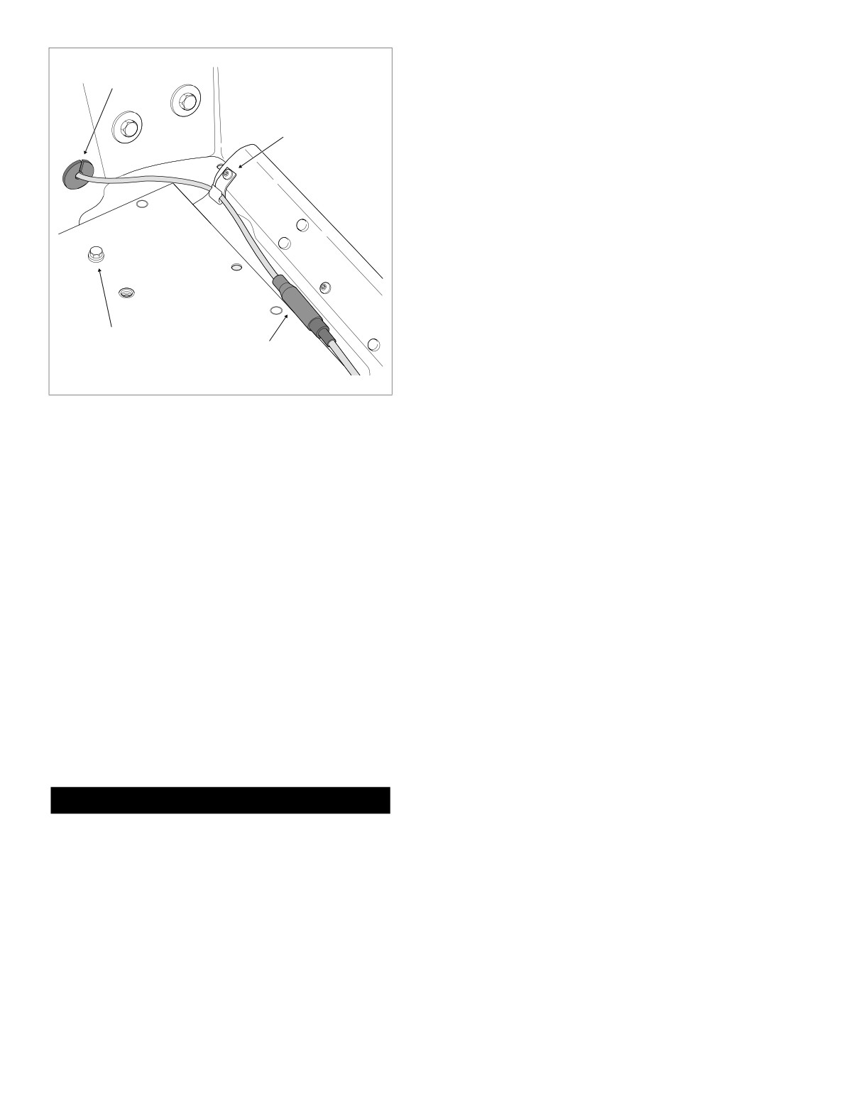
HOME
4.
Position two spacers between bottom of luggage rack
and tabs of license plate bracket. Slide 2-1/4 inch bolts
f1467b2x
Grommet
(with flat washers) through two center holes in Tour-Pak
and luggage rack, and then through spacers and tabs of
license plate bracket. If necessary, loosen two hex bolts
Cable
at back of license plate bracket to align holes in tabs with
Clip
bolts. Install flat washers and nylon cap locknuts on bolts
and tighten until snug. See inset of Figure 2-142.
5.
In a crosswise pattern, alternately tighten five bolts to
96-120 in-lbs (10.8-13.5 Nm). Be sure that concavity on
each spacer is inline with the rail and has not rotated out
of position.
6.
On right side of vehicle, mate pin and socket halves of 6-
place Mini-Deutsch connector. Feed connector back up
into right side speaker box pressing trim ring into hole.
7.
Pass CB antenna cable through hole in Tour-Pak. Cap-
Tour-Pak
ture cable in grommet. Install grommet in hole with the
Mounting Bolt
CB Antenna
larger OD facing inside.
Cable Connector
8.
Mate pin and socket halves of 1-place CB antenna cable
connector. Capture cable in two clips at bottom of Tour-
Figure 2-143. Disconnect CB Antenna Cable Connector
Pak. See Figure 2-143.
9.
Moving to left side of vehicle, mate pin and socket halves
of 6-place Mini-Deutsch connector. Feed connector back
12. Holding nylon cap locknuts at bottom of Tour-Pak,
up into left side speaker box pressing trim ring into hole.
remove five bolts (with flat washers) to release Tour-Pak
from luggage rack. Luggage rack spacers will become
10.
Capture rear headset receptacle in bracket at bottom of
free as nuts are removed. Be sure to have a firm grasp
left side speaker box.
on the Tour-Pak as the last bolt is removed. See Figure
11.
Feed socket connectors and main harness conduit
2-142.
through hole in Tour-pak. Capture conduit in grommet.
Install grommet in hole with the larger OD facing inside.
12.
Mate pin and socket halves of Tour-pak lights connector
INSTALLATION
[12], 3-place Multilock, and tuck into cavity inside Tour-
Pak. See Figure 2-140.
1.
Place Tour-Pak on luggage rack and open lid.
13.
Rotate knurled lock ring in a clockwise direction to mate
2.
Align rear center hole in Tour-Pak with same hole in lug-
pin and socket halves of Radio antenna cable connector.
gage rack. Slide 2 inch bolt (with flat washer) through
Capture cable in two clips at bottom of Tour-Pak.
ring terminal of radio antenna ground, and then through
Tour-Pak and luggage rack holes. At bottom of luggage
14.
Install bulb socket on left side of Tour-pak.
rack, install spacer (concave side up) and nylon cap
15.
Install molded liner in Tour-Pak. Install map pocket and
locknut on bolt. With concavity on spacer inline with the
secure using acorn nuts (with flat washers). Close Tour-
rail, hold nut and tighten bolt until snug.
Pak.
CAUTION
Always install the mounting bolts from inside the Tour-
Pak. If the bolts are installed upside down, then the ends
of the bolts can tear the molded liner and scratch
objects, such as helmets, stored inside the Tour-Pak.
3.
Install remaining
2 inch bolts (with flat washers and
nylon cap locknuts) in two front Tour-Pak and luggage
rack holes (one each side) in the manner described
under step 2 above.
2-114
2004 Touring: Chassis
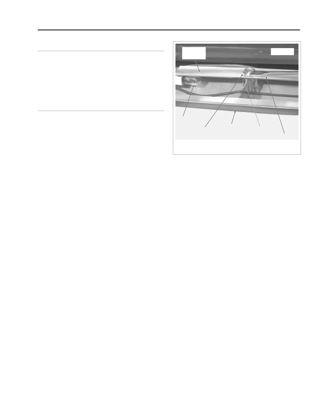
HOME
TOUR-PAK LIGHTS/BACKREST/SPEAKER BOX
2.27
GENERAL
Mounting
Tour-Pak
All domestic model Tour-Paks are equipped with side marker
Bracket
lights. Ultra models also have a wrap-around rear light
assembly that contains two 2-filament lamps. One filament is
a supplemental brake light and the other a supplemental tail
lamp.
SIDE MARKER LIGHTS
FLHTC/U
Bulb
BULB/LENSE REPLACEMENT
Lense
Eyelet
Stepped
1.
Open Tour-Pak.
Rib
Screwdriver
2.
On Ultra models, open map pocket and remove acorn
nuts
(with flat washers). Remove map pocket and
f1810x2x
molded liner from Tour-Pak.
3.
Remove three T15 TORX screws to release lens at side
Figure 2-144. Remove Eyelets to Release
of Tour-Pak.
Mounting Bracket From Lense
4.
Using the blade of an X-Acto knife or small screwdriver,
gently pry up three eyelets on inboard side of mounting
bracket. See Figure 2-144. Remove eyelets and then
3.
Close Tour-Pak. Turn Tour-Pak over and remove remain-
remove mounting bracket from lense. Discard eyelets if
ing six flange nuts at bottom.
damaged.
4.
Place Tour-Pak topside up and open lid. Reach inside
5.
Remove bulb from socket and discard. Install new bulb
Tour-Pak and remove metal plate pulling threaded studs
in socket.
from holes at bottom.
6.
Align holes in mounting bracket with those in lense.
5.
Locate 2-place Multilock connector in channel at bottom
Push three eyelets through mounting bracket holes into
of Tour-Pak. Remove masking tape if necessary. See
bosses of lense. Use new eyelets if damaged.
Figure 2-145.
7.
Place lense assembly into position at side of Tour-Pak,
but exercise caution to avoid pinching or kinking wires.
6.
Depress button on socket side of Multilock connector
Note that center rib on inboard side of lense has a
and separate pin and socket halves.
stepped area for routing of the top wire. See Figure 2-
7.
Remove three T15 TORX screws to release lens at side
144.
of Tour-Pak.
8.
From inside Tour-Pak, install three T15 TORX screws.
8.
Compress grommet at side of Tour-Pak and push
9.
On Ultra models, install molded liner in Tour-Pak. Install
through hole to outboard side. Feed conduit and socket
map pocket and secure using acorn nuts (with flat wash-
through hole to release side marker light assembly.
ers).
10.
Close Tour-Pak.
INSTALLATION
REMOVAL
1.
Feed socket and conduit of new side marker light
assembly through hole at side of Tour-Pak.
1. Remove Tour-Pak. See Section 2.26 TOUR-PAK, RE-
2.
Compress grommet on conduit and install in hole.
MOVAL, either FLHTC or FLHTCU. Move Tour-Pak to
bench area.
3.
Place lense assembly into position at side of Tour-Pak,
2. Open Tour-Pak. Holding Phillips screw inside Tour-Pak
but exercise caution to avoid pinching or kinking wires.
(rear right corner), remove flange nut at bottom to
Note that center rib on inboard side of lense has a
release loading coil bracket. Remove Phillips screw with
stepped area for routing of the top wire. See Figure 2-
external tooth lockwasher.
144.
2004 Touring: Chassis
2-115
HOME
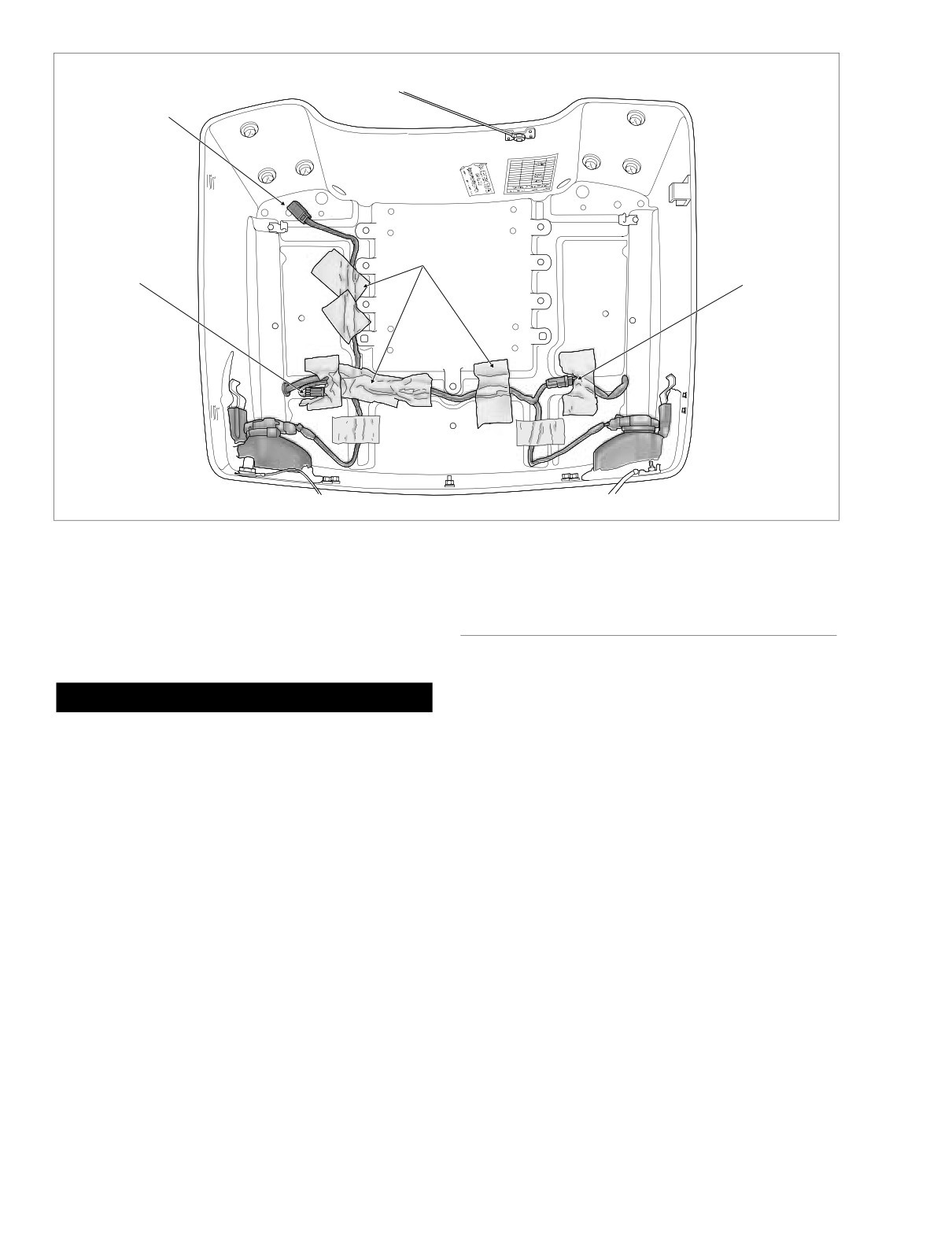
Tour-Pak Lights
f1753x2x
Connector [12]
3-place Multilock
Left Side
Right Side
Side Marker Light
Masking
Side Marker Light
Connector
Tape
Connector
2-place Multilock
2-place Multilock
Figure 2-145. Side Marker Light Connectors and Conduit
4.
From inside Tour-Pak, install three T15 TORX screws.
WRAP-AROUND LIGHT ASSEMBLY
5.
Mate pin and socket halves of 2-place Multilock connec-
FLHTCU
tor. Be sure that connector and conduit are positioned in
channel at bottom of Tour-Pak.
BULB REPLACEMENT
CAUTION
1.
Open Tour-Pak.
2.
Open map pocket and remove acorn nuts (with flat
If conduit and connector are not completely captured in
washers). Remove map pocket and molded liner from
channel at bottom of Tour-Pak, installation of metal plate
Tour-Pak.
can pinch wires or damage connector.
3.
Depress external latch and rotate bulb socket to release
6.
Place masking tape over channel to secure position of
from lens.
connector and conduit. See Figure 2-145.
4.
Remove bulb from socket and discard.
7.
With the square cut positioned at the front left corner,
5.
Install new bulb in socket.
install metal plate at bottom of Tour-Pak so that threaded
6.
Rotate bulb socket to install in lens.
studs exit holes at bottom.
7.
Install molded liner in Tour-Pak. Install map pocket and
8.
Place loading coil into position aligning hole in bracket
secure using acorn nuts (with flat washers).
with hole in rear right corner of metal plate. Slide Phillips
8.
Close Tour-Pak.
screw (with external tooth lockwasher) through holes. At
bottom of Tour-Pak, install flange nut on Phillips screw.
9.
Close lid and turn Tour-Pak over. Install six flange nuts
REMOVAL
on threaded studs of metal plate.
1.
Open Tour-Pak. Open map pocket and remove acorn
10. Install Tour-Pak on vehicle. See Section 2.26 TOUR-
nuts
(with flat washers). Remove map pocket and
PAK, INSTALLATION, either FLHTC or FLHTCU.
molded liner from Tour-Pak.
2-116
2004 Touring: Chassis
HOME
INSTALLATION
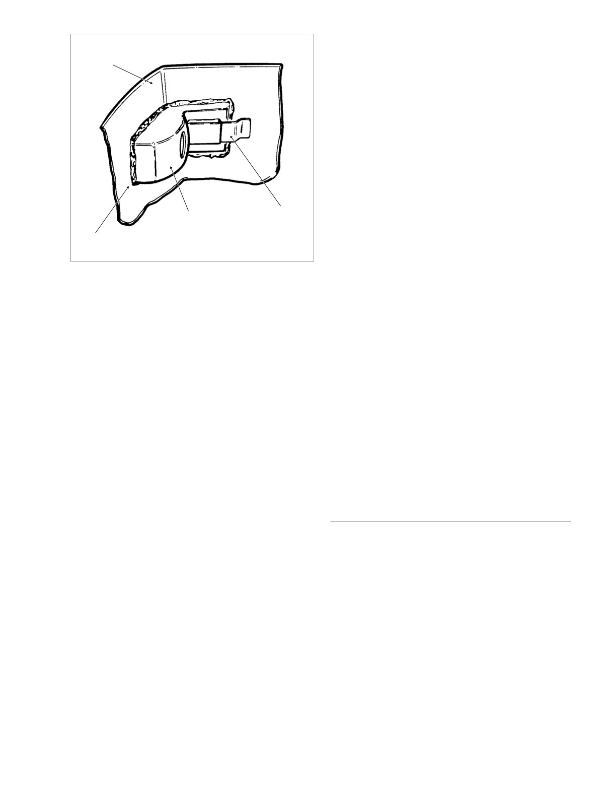
f1257x2x
Tour-Pak
1.
Install light bar, metal clips and flange nuts to secure
light bar to Tour-Pak. Inside Tour-Pak, use RTV silicone
sealer (Part No. 99710-88) to seal perimeter of light bar.
See Figure 2-146.
2.
Install radio antenna mast into lamp housing. Thread
connector stud into mast. Turn
1/2 in.-20 UNF nut
(installed on connector during removal) in a clockwise
direction to tighten.
3.
Remove 1/2 in.-20 UNF nut and jam nut. Install large flat
washer, ring terminal and internal tooth lockwasher onto
connector. Reinstall jam nut and tighten.
4.
Rotate knurled lock ring in a clockwise direction to mate
pin and socket halves of Radio antenna cable connector.
Metal Clip
Capture cable in rear clip at bottom of Tour-Pak.
Bulb Housing
5.
On right side of Tour-Pak, install CB antenna mast into
Caulking
lamp housing. Install stud into mast and tighten with 2.5
mm allen head wrench.
6.
Place loading coil into position aligning hole in bracket
Figure 2-146. Wrap-Around Light Assembly
with hole in rear right corner of Tour-Pak. Slide Phillips
screw (with external tooth lockwasher) through holes. At
bottom of Tour-Pak, install flange nut on Phillips screw.
2.
Depress external latch and rotate housing to release
bulb sockets from both sides of Tour-Pak.
7.
Install flat washer, ring terminal and Keps nut onto load-
ing coil stud. Tighten Keps nut.
3.
Disconnect 1-place CB antenna cable connector on right
8.
Mate pin and socket halves of 1-place CB antenna cable
side of Tour-Pak. Release cable from rear clip at bottom
connector. Capture antenna cable in rear clip at bottom
of Tour-Pak.
of Tour-Pak.
4.
Remove Keps nut, ring terminal and flat washer from
9.
Install bulb sockets on both sides of Tour-pak.
loading coil stud.
10.
Install molded liner in Tour-Pak. Install map pocket and
secure using acorn nuts. Close Tour-Pak.
5.
Holding Phillips screw, remove flange nut at bottom of
Tour-Pak to release loading coil bracket. Remove Phil-
11.
Install SWR meter. Check SWR following procedure in
lips screw (with external tooth lockwasher) and loading
Section
6 of the
2004 ELECTRICAL DIAGNOSTIC
coil from vehicle.
MANUAL (Part No. 99497-04). When the antenna is
adjusted, remove the SWR meter and tighten the
6.
Using a 2.5 mm allen head wrench, remove loading coil
antenna connector at the transceiver.
stud. Remove CB antenna mast from lamp housing.
7.
On left side of Tour-Pak, rotate knurled lock ring in a
PASSENGER BACKREST
counter-clockwise direction to separate pin and socket
FLHTCU
halves of Radio antenna cable connector. Release cable
from rear clip at bottom of Tour-Pak.
REMOVAL
8.
Remove jam nut from Radio antenna cable connector at
back of Tour-Pak. Remove internal tooth lockwasher,
1.
Open Tour-Pak. Open map pocket and remove acorn
ring terminal and large flat washer from connector.
nuts
(with flat washers). Remove map pocket and
molded liner from Tour-Pak.
9.
Install jam nut back onto connector. Thread a 1/2 in.-20
UNF nut onto connector until contact is made with jam
2.
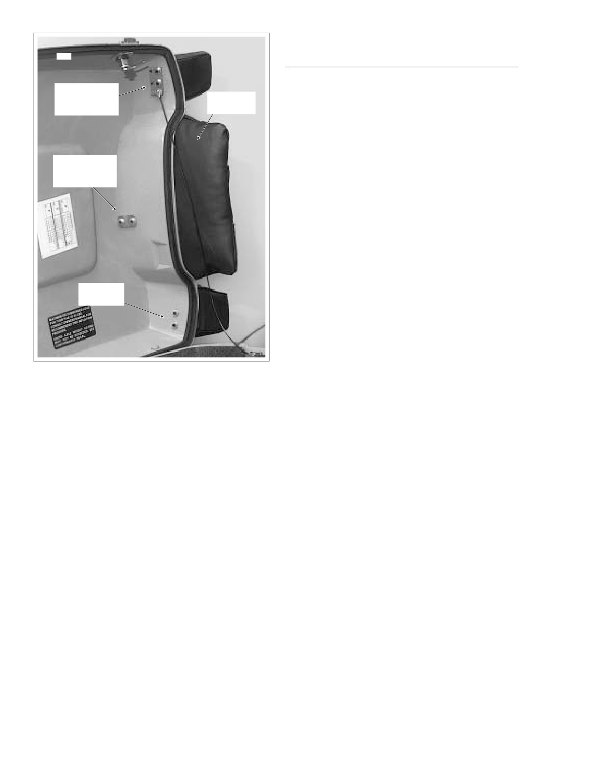
Remove two locknuts and backplate to detach center
nut. Turn jam nut to in a counter-clockwise direction to
backrest from Tour-Pak cover. See Figure 2-147.
remove connector stud from radio antenna mast.
3.
Remove two locknuts and backplate to detach right side
Remove mast from lamp housing.
backrest from cover.
4.
Remove two locknuts to detach left side backrest from
10.
Remove caulking from around light bar. Remove four
cover.
flange nuts and metal clips to free light bar from Tour-
Pak. See Figure 2-146.
5.
Remove backrest.
2004 Touring: Chassis
2-117
HOME
SPEAKER BOX
5142
FLHTCU
Right Side
REMOVAL
Fasteners
Passenger
and Backplate
Backrest
1.
Remove trim ring and gently pull on wire harness to
draw 6-place Mini-Deutsch connector out of speaker
box. Depress external latch and use a rocking motion to
separate pin and socket halves.
2.
Open Tour-Pak. Open map pocket and remove acorn
Center
nuts
(with flat washers). Remove map pocket and
Fasteners
molded liner from Tour-Pak.
and Backplate
3.
Remove three bolts with flat washers to free speaker box
from Tour-Pak.
INSTALLATION
1.
Install three bolts with flat washers to secure speaker
box to Tour-Pak. Alternately tighten bolts to 25-35 in-lbs
(2.8-4.0 Nm).
Left Side
Fasteners
2.
Install molded liner in Tour-Pak. Install map pocket and
secure using acorn nuts (with flat washers). Close Tour-
Pak.
3.
Mate pin and socket halves of 6-place Mini-Deutsch con-
nector. Feed connector back up into speaker box press-
ing trim ring into hole.
Figure 2-147. Tour-Pak Cover (Underside)
INSTALLATION
1.
Position backrest against Tour-Pak cover.
2.
From inside Tour-Pak, install two locknuts with backplate
to attach center backrest to cover.
3.
Install two locknuts and backplate to attach right side
backrest to cover.
4.
Install two locknuts to attach left side backrest to cover.
5.
Install molded liner in Tour-Pak. Install map pocket and
secure using acorn nuts (with flat washers). Close Tour-
Pak.
2-118
2004 Touring: Chassis
HOME
LOWER FAIRING/ENGINE GUARD
2.28
LOWER FAIRING
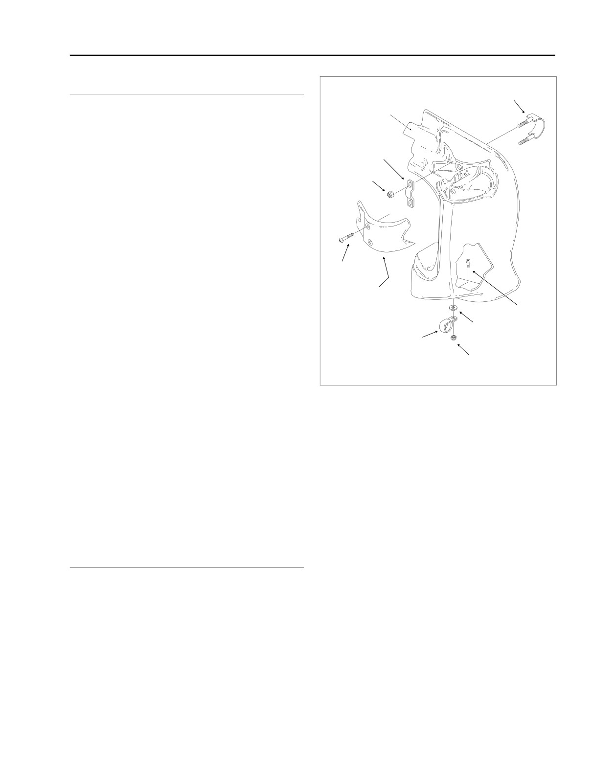
U-Bolt
Ear
REMOVAL
1. Remove two screws from fairing lower cap. See Figure
2-148.
Retainer
2. Hold locknut at bottom of fairing lower, and using a T40
TORX drive head, turn inside screw to free assembly
Locknut
from engine guard clamp. Discard rubber washer.
3. Remove two locknuts to free retainer from upper rail of
engine guard. From within glove box, remove U-bolt.
4. Remove glove box from fairing lower. Remove fairing
lower from vehicle.
5. Repeat steps 1-4 on other side of vehicle.
Screw
INSTALLATION
Fairing
Lower Cap
1. Place fairing lower into position on vehicle.
Screw
2. Holding screw inside fairing lower, install new rubber
Rubber
washer, clamp and locknut to attach fairing bottom to
Washer
engine guard. Do not tighten locknut.
Clamp
3.
Place glove box into fairing lower. From within glove box,
Locknut
install U-bolt so that it encircles the upper rail of the
f1077bxx
engine guard. Loosely install retainer and locknuts.
4. Adjust the fairing lower so that ear at top inboard side is
Figure 2-148. Fairing Lower (Right Side) - FLHTCU
approximately 1/4 inch (6.4 mm) from frame downtube.
Verify that fairing lower is square, and then alternately
tighten locknuts to 35-40 in-lbs (4.0-4.5 Nm).
3.
Remove hex socket screw (with flat washer) to release
5. Hold locknut at bottom of fairing lower, and using a T40
tab at top of engine guard from slot at base of steering
TORX drive head, turn inside screw to fasten assembly
head.
to engine guard clamp. Tighten screw to 90-100 in-lbs
(10.2-11.3 Nm).
6. Install two screws to secure fairing lower cap to fairing
INSTALLATION
lower. Tighten screws to 10-15 in-lbs (1.1-1.7 Nm).
7. Repeat steps 1-6 on other side of vehicle.
1.
Insert tab at top of engine guard into slot at base of
steering head. Start hex socket screw (with flat washer)
to hang engine guard.
ENGINE GUARD
2.
Position ends of engine guard outboard of frame weld-
ments on each side of motorcycle. Install T40 TORX
screws positioning flanged locknuts on inboard side of
frame weldments.
REMOVAL
3.
Alternately tighten three screws to 15-20 ft-lbs (20.3-
1. Remove fairing lowers, if present. See LOWER FAIR-
27.1 Nm).
ING, REMOVAL, in this section. Remove fairing lower
clamps from engine guard.
4.
Install fairing lowers, if present, but first install fairing
lower clamps on each side of engine guard. See
2. Remove T40 TORX screws (with flanged locknuts) to
release ends of engine guard from frame weldments.
LOWER FAIRING, INSTALLATION, in this section.
2004 Touring: Chassis
2-119
HOME
UPPER FAIRING/WINDSHIELD (FLHT/C/U)
2.29
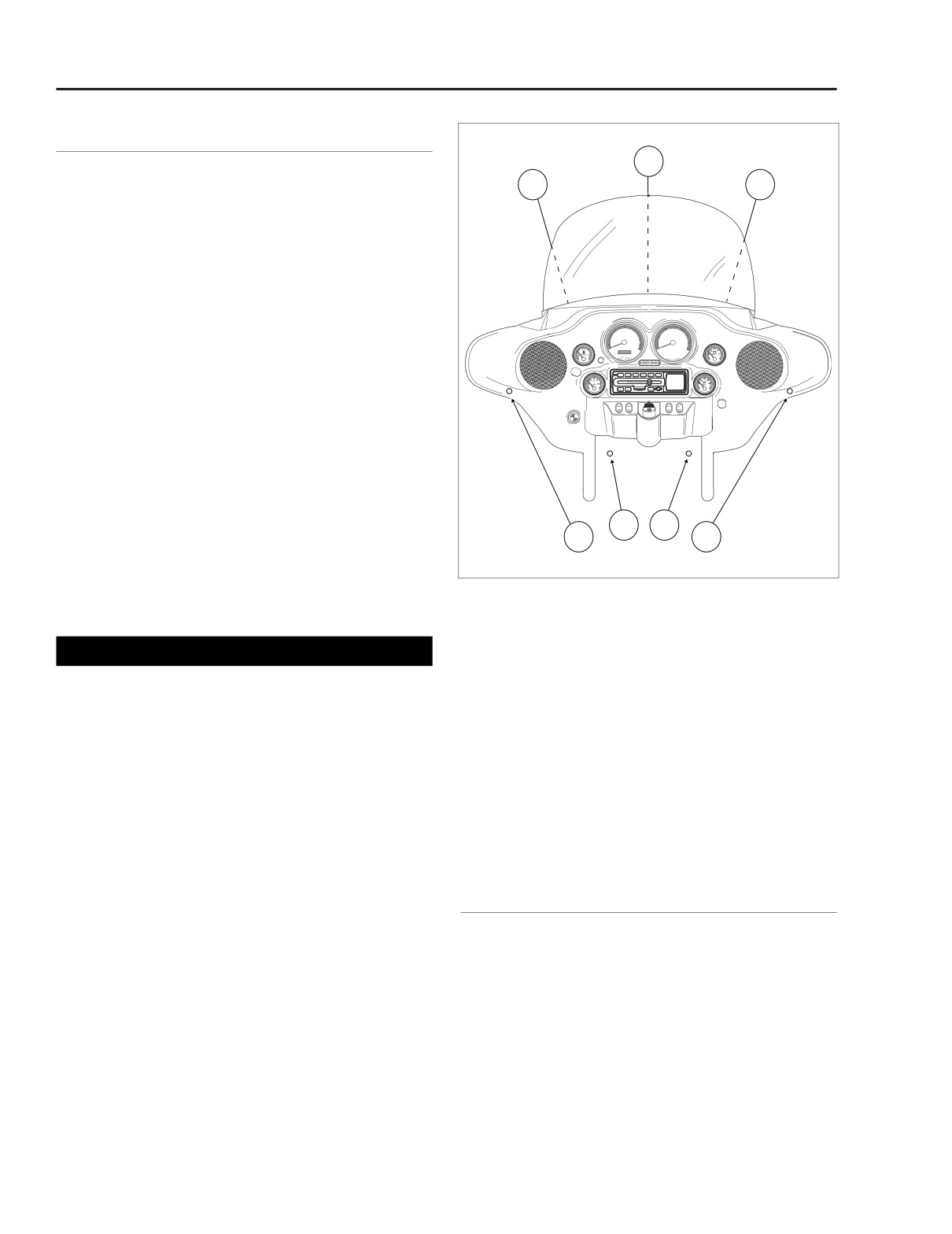
OUTER FAIRING/WINDSHIELD
T27 TORX Screws
2
REMOVAL
1
3
1.
Remove maxi-fuse. See Section 8.3 SYSTEM FUSES,
MAXI-FUSE, REMOVAL.
2.
Remove the outer fairing as follows:
a. Standing at the front of the vehicle, use a T27 TORX
drive head to remove the three outer fairing screws
(with flat washers) just below the windshield. See
40
50
60
70
80
30
40
50
30
90
20
60
20
100
10
70
Figure 2-149.
10
0
MPH
120
110
0
RPMx100
80
b. Moving to the inner fairing side, remove the two fair-
ing screws just above the wind deflectors on the left
and right side.
c. Turn the handlebar to the right and remove the outer
fairing screw reaching in below the left side of the
fairing cap. Turn the handlebar to the left and
remove the fairing screw below the right side of the
fairing cap.
d. Tilting the outer fairing toward the front, squeeze the
6
7
4
5
two external tabs to remove the wire connector at
f2029x2x
the back of the headlamp assembly.
e. Lift the fairing
(with headlamp assembly) off the
Figure 2-149. Outer Fairing TORX Screw Locations
motorcycle.
e. Turn the handlebar to the left and start the outer fair-
CAUTION
ing screw reaching in below the right side of the fair-
Since the outer fairing screws hold the windshield in
ing cap. Turn the handlebar to the right and start the
place, the windshield may fall to the floor if not removed.
fairing screw below the left side of the fairing cap.
f.
Alternately tighten the four fairing screws on the
3.
Remove the windshield.
inner fairing side to 20-30 in-lbs (2.3-3.4 Nm).
g. Moving to the front of the vehicle, tighten the outer
fairing screws below the windshield to 25-30 in-lbs
INSTALLATION
(2.8-3.4 Nm).
2.
Install maxi-fuse. See Section
8.3 SYSTEM FUSES,
1.
Install the outer fairing as follows:
MAXI-FUSE, INSTALLATION.
a. Place the fairing (with headlamp assembly) on the
motorcycle installing the wire connector at the back
of the headlamp assembly.
FAIRING CAP
b. Place the windshield in position on the inner fairing
aligning the slots with the threaded inserts.
REMOVAL
c. Using a T27 TORX drive head, start the three outer
fairing screws
(with flat washers) just below the
1.
Partially disassemble domestic ignition switch as follows:
windshield.
NOTE
d. Moving to the inner fairing side, start the two fairing
For partial disassembly of HDI ignition switch, see Section
screws just above the wind deflectors on both the
8.18 IGNITION/LIGHT KEY SWITCH AND FORK LOCK,
left and right side.
FLHT/C/U, FLTR (INTERNATIONAL), REMOVAL, steps 1-4.
2-120
2004 Touring: Chassis
HOME
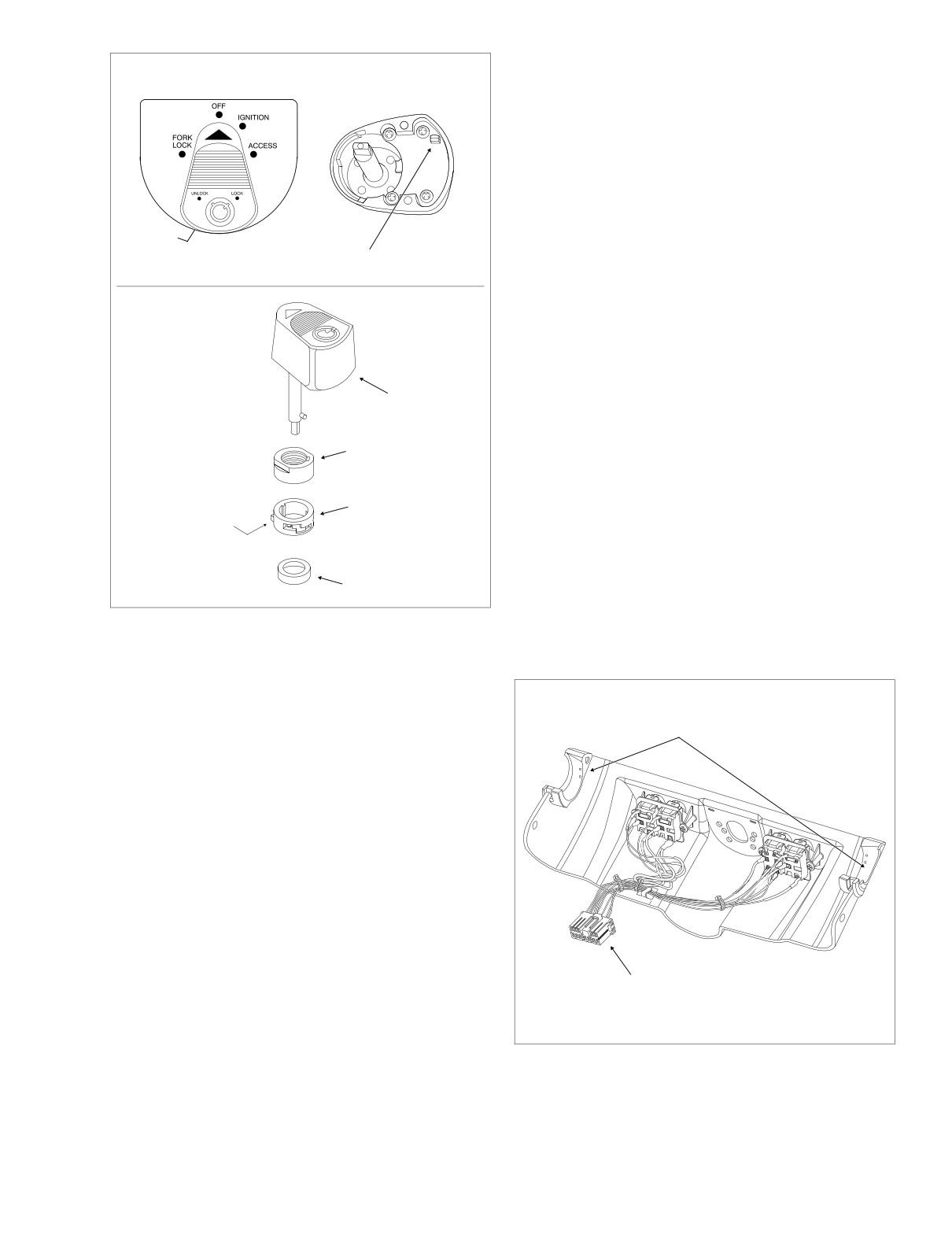
4.
Remove the fairing cap from the motorcycle. See Figure
TOP VIEW
BOTTOM VIEW
2-151.
INSTALLATION
1.
Verify that the rubber grommets are installed on each
side of the fairing cap. Barbs on cap fit into holes in
grommets. See Figure 2-151.
2.
Connect the Fairing cap switch connector [105], 12-
Button
place Multilock (black), on the right side of fairing cap.
Button
3.
With the forks turned fully to the left, install fairing cap
f1240x2x
f1476x8x
over ignition switch housing.
f1297b2x
4.
Using a T27 TORX drive head, start two fairing cap
screws (with flat washers). Verify that grommets in fair-
ing cap fully capture handlebar along with throttle and
clutch cables.
5.
Assemble domestic ignition switch as follows:
Knob
NOTE
For assembly of HDI ignition switch, see Section 8.18 IGNI-
Nut
TION/LIGHT KEY SWITCH AND FORK LOCK, FLHT/C/U,
FLTR (INTERNATIONAL), INSTALLATION, steps 5-10.
a.
Install switch position plate fitting tabs in slots of fair-
Tab
Collar
ing cap. Plate snaps in place when properly
Down and Forward
installed. Exercise care to avoid breaking tabs.
Replace plate if tabs are broken.
b.
Slide spacer over threaded post of ignition switch
Spacer
housing until it contacts switch position plate. Slide
collar over post with the tab side down (and for-
Figure 2-150. Ignition Switch Knob (Domestic)
ward). Install nut, and using a 7/8 inch wrench on
flats, tighten to 50-70 in-lbs (5.7-7.9 Nm).
a. See upper frame of Figure 2-150. To remove the
ignition switch knob, insert the Ignition Switch key
and turn to the UNLOCK position. Leaving the key
Rubber
f1305b2x
installed, rotate the knob to ACCESS. Depressing
Grommet
the release button at bottom (left side) with a small
screwdriver, push key down and turn an additional
60 degrees in a counter-clockwise direction. Lift and
remove knob.
b. Using a 7/8 inch wrench on flats, loosen switch nut
and remove from threaded post of ignition switch
housing. Remove collar and spacer. See lower
frame of Figure 2-150.
c. Gently remove the switch position plate by pulling
tabs from slots in fairing cap.
2.
Using a T27 TORX drive head, remove the two screws
(with flat washers) that secure fairing cap to left and right
sides of inner fairing.
3.
With the forks turned fully to the left, disconnect the Fair-
Fairing Cap
Switch Connector [105]
ing cap switch connector
[105],
12-place Multilock
12-Place Multilock
(black), from behind right side of fairing cap. Depress the
button on the socket terminal side of the connector
(plug) to pull apart the pin and socket halves.
Figure 2-151. Fairing Cap Assembly (FLHT/C/U)
2004 Touring: Chassis
2-121