Harley Davidson 2004 Touring Models. Service Manual - page 34
HOME
f1903x2x
Ram
Socket
Extension
Anchor
Weldment
Socket
Socket
Wood
Block
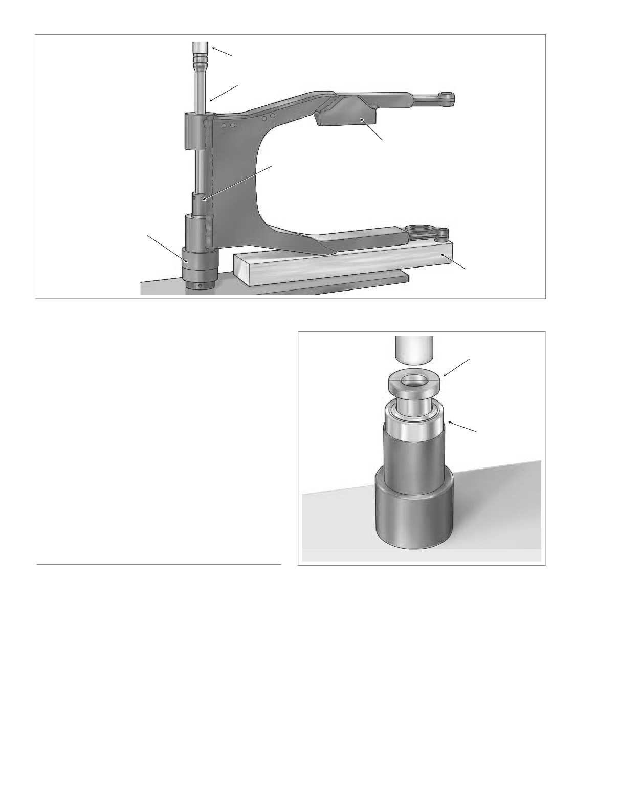
Figure 2-98. Press Out Drive Side Bearing
16. Holding left side nut within rubber mount, remove right
side locknut from end of pivot shaft. Remove cup
f1967x2x
washer.
Spacer
17. Using a suitable drift, tap pivot shaft toward left side of
vehicle.
18. Moving to left side, pull pivot shaft assembly (pivot shaft,
locknut, cup washer, rubber mount and outer spacer) out
of transmission mount and left side swingarm. See
Bearing
Figure 2-102.
19. Standing at rear of vehicle, work rear swingarm free of
transmission mount and rear swingarm brackets.
20. Remove outer spacer from right side swingarm tube.
21. Remove rubber mount from behind right side swingarm
bracket.
DISASSEMBLY/ASSEMBLY
Figure 2-99. Press Spacer Into Bearing
Bearing Removal
1. Move rear swingarm to an hydraulic press.
4. Slide driver handle (or long socket extension) through
the brake side swingarm tube and bearing until it con-
2. Place swingarm on its side, so that the brake side is on
tacts driver (or large socket) placed on inboard side of
top. The brake side is easily recognized by the anchor
drive side bearing.
weldment for mounting of the brake caliper.
5. Center driver handle (or long socket extension) under
3. Support the swingarm with a block of wood and a large
ram and press drive side bearing from rear swingarm.
socket as shown in Figure 2-98. Verify that assembly is
6. Remove tools from rear swingarm. Turn swingarm over
square and the bearing bore is completely vertical.
and repeat steps 3-5 to press out brake side bearing.
2-82
2004 Touring: Chassis
HOME
a. Place swingarm on its side, so that the brake side is
on top. The brake side is easily recognized by the
anchor weldment for mounting of the brake caliper.
Drive Side
Brake Side
Driver
Driver
b. With the spacer inboard, insert bearing into out-
board side of brake side swingarm tube.
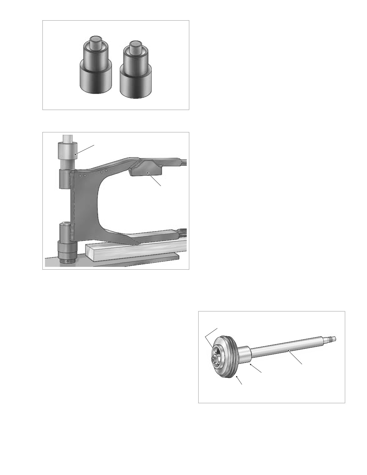
c. Insert driver stamped “Brake Side” into swingarm
tube until it contacts installed bearing. Center driver
under ram and press on brake side bearing until
shoulder on tool makes contact with casting of swin-
garm. See Figure 2-101.
d. Remove tool and turn rear swingarm over. With the
spacer inboard, insert bearing into outboard side of
drive side swingarm tube.
Figure 2-100. Rear Swingarm Bearing Installer (HD-
e. Insert driver stamped “Drive Side” into swingarm
45327)
tube until it contacts installed bearing. Center driver
under ram and press on drive side bearing until it
bottoms. Shoulder on tool will not make contact
Brake Side
f1909x2x
with casting of swingarm.
Driver
f.
Remove tool from swingarm. Remove swingarm
from hydraulic press.
Pivot Shaft Disassembly
Anchor
1. Partially install locknut on right side of pivot shaft. Install
Weldment
second locknut on right side until it contacts the first.
Holding first locknut to prevent rotation of shaft, remove
left side locknut. See Figure 2-102.
2. Remove cup washer, rubber mount and outer spacer.
3. Remove right side locknuts from pivot shaft.
Pivot Shaft Assembly
1.
With larger OD outboard, slide outer spacer onto left
side of pivot shaft until counterbore contacts shoulder on
shaft.
Figure 2-101. Press In Brake Side Bearing
2.
Install rubber mount with the flat side inboard toward
outer spacer.
3.
Install cup washer with the concave side facing in toward
Bearing Installation
the rubber mount.
1. Obtain new rear swingarm bearings. Bearings and spac-
ers must be assembled before installation. Proceed as
follows:
Right Side
Locknut and
a. Obtain REAR SWINGARM BEARING INSTALLER
Cup Washer
(HD-45327). See Figure 2-100.
b. With the nose topside, center one of the drivers
under ram of hydraulic press.
c. Place bearing over nose of driver. With the collar
topside, place spacer over nose and into bearing.
Pivot
See Figure 2-99.
Spacer
Shaft
d. Apply pressure to spacer until it bottoms in bearing.
Rubber
e. Repeat step to assemble second swingarm bearing.
Mount
f1914x2x
2. Install assembled bearings into rear swingarm. Proceed
as follows:
Figure 2-102. Pivot Shaft Assembly
2004 Touring: Chassis
2-83
HOME
4.
Apply two drops of Loctite Medium Strength Thread-
5. Install lockwasher and flat washer on the lower shock
locker 243 (blue) to threads of left side locknut, and then
mounting bolt. Insert bolt through the shock bottom
start on shaft.
bushing. Apply two or three drops of Loctite Medium
Strength Threadlocker 243 (blue) to threads. Start bolt
5.
Partially install locknut on right side of pivot shaft. Install
into rear swingarm mount. Tighten bolt to 35-40 ft-lbs
second locknut on right side until it contacts the first.
(47-54 Nm). Repeat step on opposite side of vehicle.
Holding second locknut to prevent rotation of shaft,
tighten left side locknut to 40-45 ft-lbs (54-61 Nm).
6. Install belt guard at bottom of left side swingarm. Push
belt guard toward the rear of the vehicle until front screw
6.
Remove right side locknuts from pivot shaft.
engages small end of slot. Install two rear screws, and
then tighten front screw.
7. Capture rear brake line hose in two cable clips at top of
INSTALLATION
right side swingarm. Snap cable clips closed.
8. Place wheel in rear swingarm. Slide wheel far enough
1.
With the slot on the outboard side between the twelve
forward to slip belt over sprocket and then slide the
and one o’clock positions, install rubber mount behind
wheel back.
rear swingarm bracket on right side of vehicle. Be sure
that index tab cast on inboard side of bracket fully
CAUTION
engages slot in rubber mount.
2.
Place outer spacer into right side swingarm tube.
Do not bend or fold belt backward or into loops smaller
than 5 inches (127 mm) in diameter. Sharp bending can
3.
With the belt on the inboard side of the left side swing-
weaken the belt and cause premature failure.
arm, work the rear swingarm into position between the
transmission mount and the rear swingarm brackets.
9.
Seat caliper on anchor weldment of rear swingarm. Posi-
Use a rubber mallet and carefully tap swingarm into
tion wheel in swingarm, so that brake disc is centered
position, if necessary.
between brake pads.
4.
The pivot shaft secures the rear swingarm and transmis-
10.
Coat the axle with Loctite ANTI-SIEZE LUBRICANT.
sion to the vehicle frame. See Figure 2-102. Install the
11.
With the larger OD on the outboard side, hold external
pivot shaft as follows:
spacer between rear swingarm and belt sprocket. Slide
axle through left side of rear swingarm, external spacer,
a.
Coat pivot shaft with Loctite ANTI-SEIZE LUBRI-
and belt sprocket into wheel hub.
CANT.
12.
When axle emerges from hub on brake disc side of
b.
From left side of vehicle, slide pivot shaft assembly
wheel, push axle through short external spacer, caliper
(pivot shaft, locknut, cup washer, rubber mount and
bracket and right side of rear swingarm.
outer spacer) through left side swingarm and trans-
13.
Rotate axle so that the flat on the threaded end is top-
mission mount. After exiting right side swingarm,
side. With the thumb down and the cam forward, install
guide end of pivot shaft through holes in rubber
adjuster cam on end of axle.
mount and right side swingarm bracket.
14.
Apply a thin film of ANTI-SIEZE LUBRICANT to the
c.
With the concave side inboard, slide cup washer
inboard side of the cone nut avoiding contact with
onto end of pivot shaft.
threads. Install cone nut on axle, but finger tighten only.
d.
Install locknut on pivot shaft. Holding left side nut on
15.
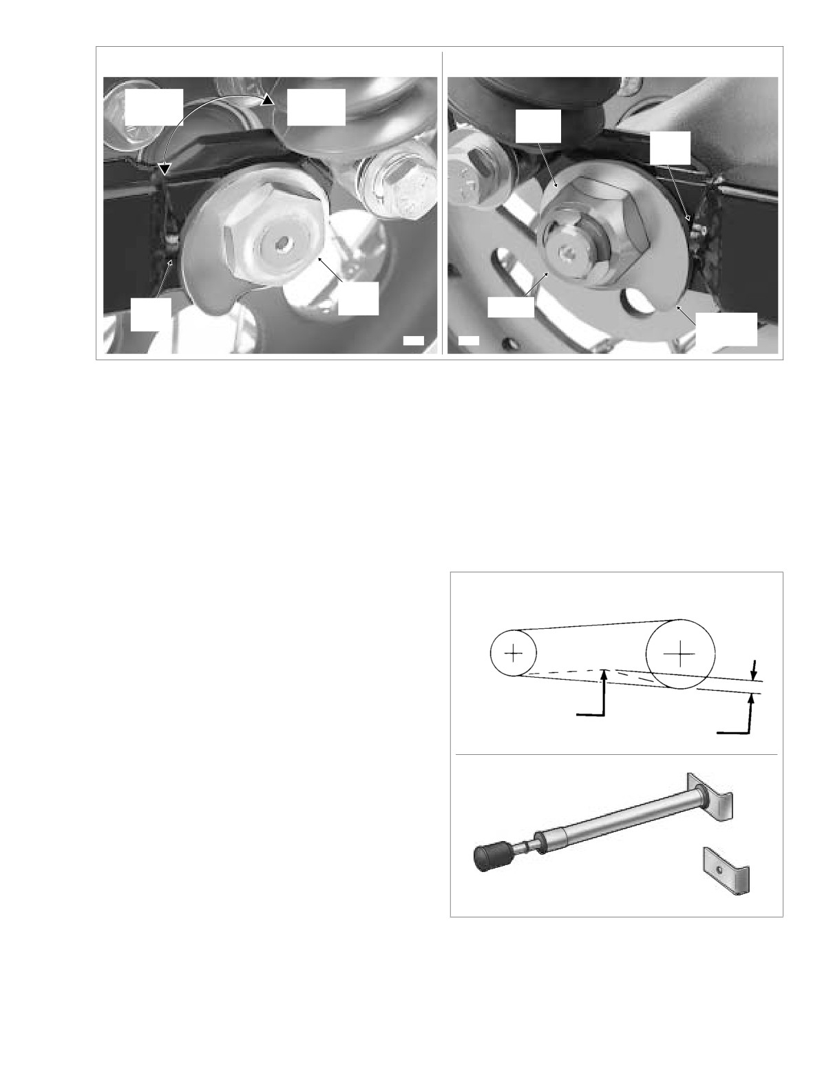
Verify that adjuster cam just contacts weld nub on both
pivot shaft, tighten locknut to 40-45 ft-lbs (54-61 Nm).
sides of rear swingarm. If necessary, push wheel for-
Now hold right side nut and tighten left side locknut
ward slightly to achieve the desired result. Snug the
using the same torque value.
cone nut to 15-20 ft-lbs (20-27 Nm). See Figure 2-103.
e.
Carefully raise swingarm up and down slightly to
16.
Check deflection at the loosest spot in the belt. Use
verify movement (and that assembly is not in a
BELT TENSION GAUGE (HD-35381A), or install narrow
bind).
saddle (HD-35381-3) on existing gauge, and apply 10
f.
Install decorative chrome plug in right side rear
lbs. (4.5 kg) of force at the midpoint of the bottom belt
swingarm bracket.
strand. See Figure 2-104. Belt deflection should be as
follows:
g.
Moving to left side of vehicle, rotate the rubber
mount so that the slot is between the eleven and
Table 2-4. Belt Deflection in the Air
twelve o’clock positions. Install left side swingarm
bracket fitting index tab into rubber mount slot. See
Orientation
Inches
Millimeters
Figure 2-97.
Motorcycle Upright
h.
Install two bolts (with lockwashers) to secure left
3/16 - 1/4
4.8
- 6.4
With Rear Wheel in the Air
side swingarm bracket to vehicle frame. Tighten
bolts to 34-42 ft-lbs (46-57 Nm).
NOTE
See Section 6.4 SECONDARY DRIVE BELT AND SPROCKETS
for belt deflection specification with motorcycle on jiffy stand.
2-84
2004 Touring: Chassis
HOME
LEFT SIDE
RIGHT SIDE
Increase
Reduce
Belt
Belt
Deflection
Deflection
Cone
Nut
Weld
Nub
Weld
Weld
Nut
E-Clip
Nub
Adjuster
Cam
8398
8407
Figure 2-103. Move Rear Wheel Forward Until Adjuster Cams Just Contact Weld Nubs
17.
If belt is too tight, move to step
18 to increase belt
20. Recheck belt deflection to verify that it is still within spec-
deflection. If belt is too loose, reduce belt deflection as
ification.
described below:
If the belt deflection is not within specification, loosen
cone nut and then snug to 15-20 ft-lbs (20-27 Nm)
a. Rotate weld nut on left side of axle in a clockwise
before returning to step 17.
direction.
21. With the flat side out, install new E-clip in groove on right
b. Check belt deflection. Apply 10 lbs. (4.5 kg) of force
side of axle.
at the midpoint of the bottom belt strand. Belt
22. Depress rear brake pedal several times to set brake
deflection should be within the range specified in
pads to proper operating position within caliper.
Table 2-4.
c. If belt is still too loose, repeat steps 17(a) through
17(b). If belt is now too tight, move to step 18.
Transmission
Rear Wheel
Sprocket
Sprocket
18.
If belt is too tight, increase belt deflection as follows:
a. Rotate weld nut on left side of axle in a counter-
clockwise direction.
b. Push wheel forward slightly so that adjuster cam
just contacts weld nub on both sides of rear swing-
arm. See Figure 2-103.
10 lbs. (4.5 kg)
of Force
c. Check belt deflection. Apply 10 lbs. (4.5 kg) of force
f1652x6x
See Table 2-4.
at the midpoint of the bottom belt strand. Belt
deflection should be within the range specified in
Table 2-4.
Belt Tension Gauge
Part No. HD-35381A
d. If belt is still too tight, repeat steps 18(a) through
18(c). If belt is now too loose, move to step 17.
19.
Holding weld nut on left side of axle, tighten cone nut on
right side to 95-105 ft-lbs (128.8-142.4 Nm).
Belt Tension Gauge Adapter
NOTE
Part No. HD-35381-3
If the axle moves during tightening of the cone nut, then the
the belt deflection procedure must be restarted.
Figure 2-104. Check and Adjust Belt Deflection
2004 Touring: Chassis
2-85
HOME
1WARNING
Passenger
After installation of caliper and BEFORE moving motor-
Footboard
cycle, pump rear brake pedal until pistons push pads
Bracket
against the brake disc. If fluid pressure is not pumped
up, the rear brake will not be available the first time it is
used, a situation that could result in death or serious
injury.
23. Install both mufflers as follows:
NOTE
TORCA muffler clamps have eliminated the need for silicone
or graphite tape during assembly. To ensure sealing integrity
of muffler clamps and prevent the possibility of leakage, Har-
ley-Davidson recommends that TORCA clamp assemblies be
discarded and replaced each time they are removed.
Chrome
Plug
Left Side
Rear
a. Slide new TORCA clamp onto free end of crossover
Swingarm
pipe.
Bracket
b. Using a bungee cord, tie muffler to lower saddlebag
support rail. Install muffler on crossover pipe. Place
f1787x2x
TORCA clamp into position between crossover pipe
and muffler.
c. Tighten the two bolts (with lockwashers) to fasten
the muffler to the lower saddlebag support rail.
CAUTION
Verify that the exhaust pipes do not contact the vehicle
frame or any mounted components. Contact will cancel
the effect of the rubber isolation mounts and transmit
vibration to the rider via the vehicle frame.
Locknut
d. Verify that exhaust pipes are in alignment and do
not contact the vehicle frame or mounted compo-
nents.
e. Tighten the TORCA clamp to 45-60 ft-lbs (61-81
Nm).
f.
Open worm drive clamps and install heat shield on
crossover pipe. Position clamp so that screw is on
the outboard side in the most accessible position.
Pivot
Shaft
CAUTION
Verify that the heat shields do not contact the vehicle
frame or any mounted components. Contact will cancel
L(eft) Side
the effect of the rubber isolation mounts and transmit
Casting Stamp
vibration to the rider via the vehicle frame.
g. Remove bungee cord from muffler.
f2073x2x
Right Side
a. Slide new TORCA clamp onto free end of rear
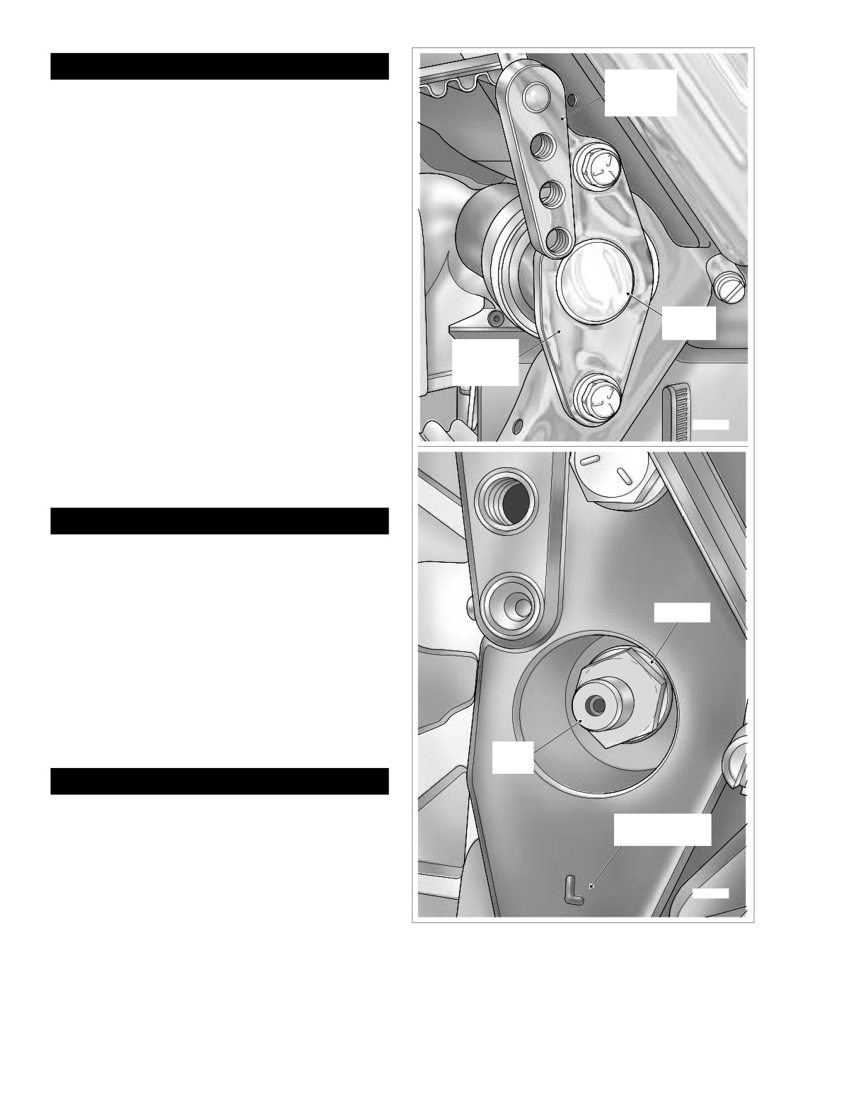
Figure 2-105. Remove Chrome Plugs and Check
header pipe.
Pivot Shaft Locknut Torque (Left Side View)
2-86
2004 Touring: Chassis
HOME
b. Using a bungee cord, tie muffler to lower saddlebag
25. Install saddlebags. See Section
2.25 SADDLEBAG,
support rail. Install muffler on rear header pipe.
INSTALLATION.
Place TORCA clamp into position between rear
NOTE
header pipe and muffler.
Remove the decorative chrome plugs in the rear swingarm
c. Tighten the two bolts (with lockwashers) to fasten
brackets and check the torque on the pivot shaft locknuts
the muffler to the lower saddlebag support rail.
every 10,000 miles (16,000 km). See Figure 2-105. Holding
right side nut on the pivot shaft, tighten left side locknut to 40-
CAUTION
45 ft-lbs (54-61 Nm). Then hold left side nut and tighten right
side locknut using the same torque value.
Verify that the exhaust pipes do not contact the vehicle
frame or any mounted components. Contact will cancel
the effect of the rubber isolation mounts and transmit
vibration to the rider via the vehicle frame.
d. Verify that exhaust pipes are in alignment and do
not contact the vehicle frame or mounted compo-
nents.
e. Tighten the TORCA clamp to 45-60 ft-lbs (61-81
Nm).
f.
Open worm drive clamps and install heat shield on
rear header pipe. Position clamp so that screw is on
the outboard side in the most accessible position.
CAUTION
Verify that the heat shields do not contact the vehicle
frame or any mounted components. Contact will cancel
the effect of the rubber isolation mounts and transmit
vibration to the rider via the vehicle frame.
g. Remove bungee cord from muffler.
24. Install socket screw with lockwasher to fasten passenger
footboard to rear swingarm bracket. Tighten screw to 15-
18 ft-lbs (20-24 Nm). Repeat step on opposite side of
vehicle.
2004 Touring: Chassis
2-87
HOME
THROTTLE CABLES (NON-CRUISE)
2.21
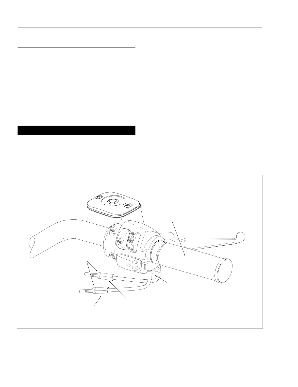
1. Slide rubber boot off throttle cable adjuster. See Figure
ADJUSTMENT
2-106. Holding cable adjuster with a 3/8 inch wrench,
loosen jam nut turning in a clockwise direction. Back jam
NOTE
nut away from cable adjuster until it stops. Turn adjuster
For throttle and idle cable adjustment or replacement on
clockwise until it contacts jam nut. Repeat procedure on
cruise equipped models, see Section 8.30 CRUISE CON-
idle cable adjuster.
TROL (FLHRC, FLTR, FLHTCU).
2. Point the front wheel straight ahead. Turn the throttle
The throttle control must operate freely without binding. With
control grip so that the throttle is wide open (fully coun-
the tension adjuster screw backed off, the throttle control grip
terclockwise) and then hold in position. Now turn the
must freely return to the closed (idle) position. The throttle
throttle cable adjuster counter-clockwise until the throttle
control also must open and close freely when the front wheel
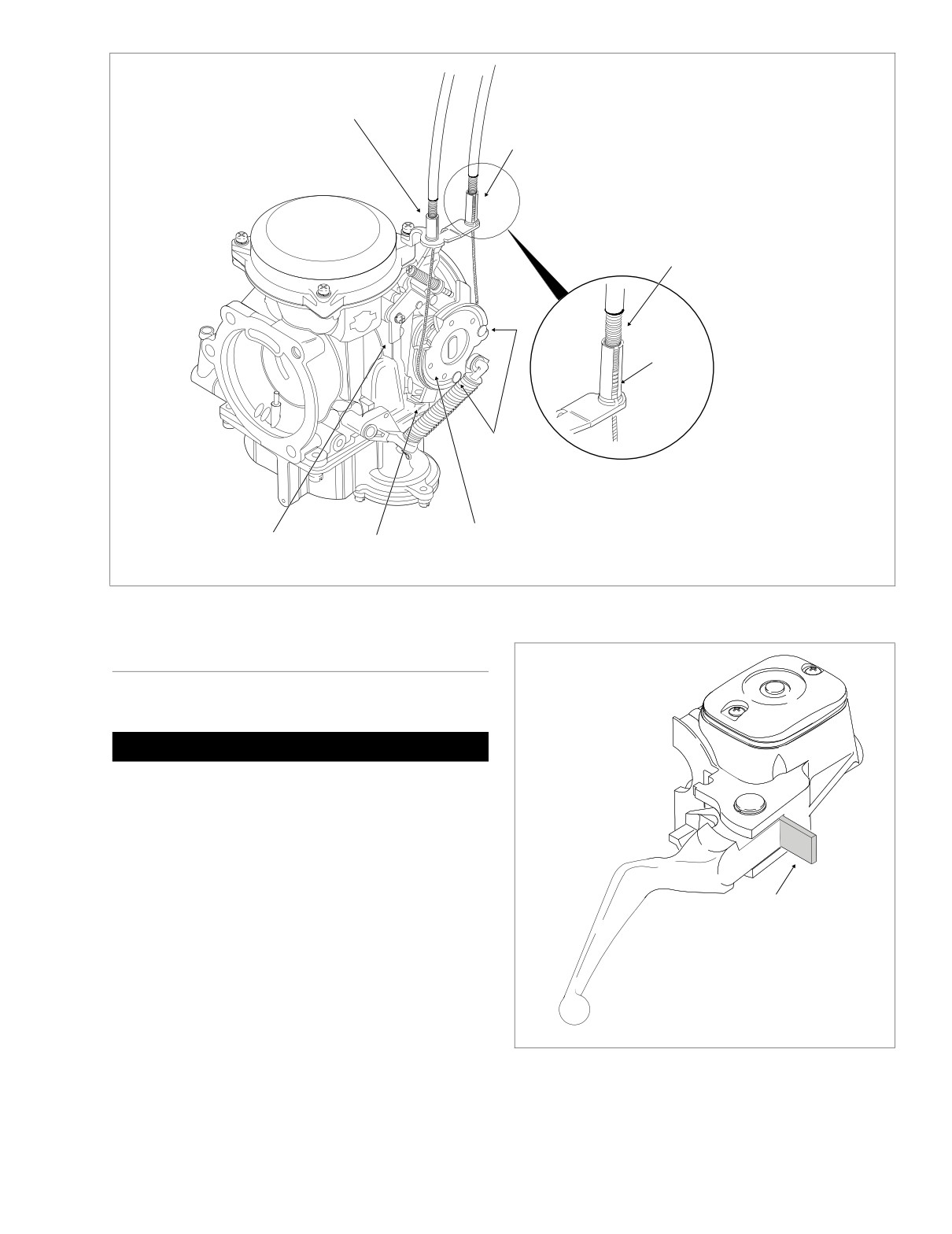
cam stop just touches the stop plate. See Figure 2-107.
is turned to both the right and left fork stops. If the throttle
Release the throttle control grip and then tighten the jam
grip does not return to the idle position freely, check the
nut against the throttle cable adjuster. Cover cable
adjuster screw tension. If the adjuster screw is backed off,
adjuster mechanism with rubber boot.
inspect the cables for short bends.
3. Turn the front wheel full right. Turn the idle cable adjuster
counterclockwise until the cable housing just touches
the spring in the cable guide (as seen through slot).
1WARNING
Work the throttle grip to verify that the throttle cable
Do not overtighten the tension adjuster screw. An over-
returns to the idle position when released. If the cable
tightened screw will prevent the engine from automati-
does not return to idle, turn the adjuster clockwise
cally returning to idle in an emergency situation. This
slightly until the correct response is achieved. Tighten
can lead to loss of vehicle control, which could result in
jam nut against the idle cable adjuster and cover cable
death or serious injury.
adjuster mechanism with rubber boot.
Throttle Control
Grip
Jam Nut
Tension
Adjuster
Screw
Throttle Cable
Idle Cable
Adjuster
Adjuster
f1376b2x
Figure 2-106. Throttle Cable Assembly - Throttle Side (FLHR)
2-88
2004 Touring: Chassis
HOME
Throttle
Cable Guide
Idle
Cable Guide
Cable
Housing
Spring
Cable
Barrel End
Throttle
Stop Plate
Throttle
Wheel
Cam Stop
f1381a2x
Figure 2-107. Throttle Cable Assembly - Carburetor Side
REMOVAL
f1225x2x
THROTTLE SIDE
CAUTION
Do not remove the switch housing assembly without first
placing the 5/32 inch (4.0 mm) cardboard insert between
the brake lever and lever bracket. Removal without the
insert may result in damage to the rubber boot and
plunger of the Front Stoplight Switch.
NOTE
Use the eyelet of an ordinary cable strap if the cardboard
insert is not available.
5/32 Inch
(4.0 mm)
1. Place the cardboard insert between the brake lever and
Cardboard
lever bracket. See Figure 2-108.
Insert
2. Using a T25 TORX drive head, remove the upper and
lower switch housing screws.
3. Using a T27 TORX drive head, loosen the upper screw
securing the handlebar clamp to the master cylinder
housing. Remove the lower clamp screw with flat
washer.
Figure 2-108. Install Cardboard Insert
2004 Touring: Chassis
2-89
HOME
4.
Remove the brass ferrules from the notches on the
inboard side of the throttle control grip. Remove the fer-
7961
rules from the cable end fittings.
Lower
5.
Remove the friction shoe from the end of the tension
Switch
adjuster screw.
Housing
NOTE
The friction shoe is a loose fit and may fall out or become dis-
lodged if the lower switch housing is turned upside down or
shaken.
Throttle
Cable Insert
(Silver)
6. Remove the throttle control grip from the end of the han-
dlebar.
Idle
Cable Insert
7.
Pull the crimped inserts at the end of the throttle and idle
(Gold)
cable housings from the lower switch housing.
For best results, use a rocking motion while pulling.
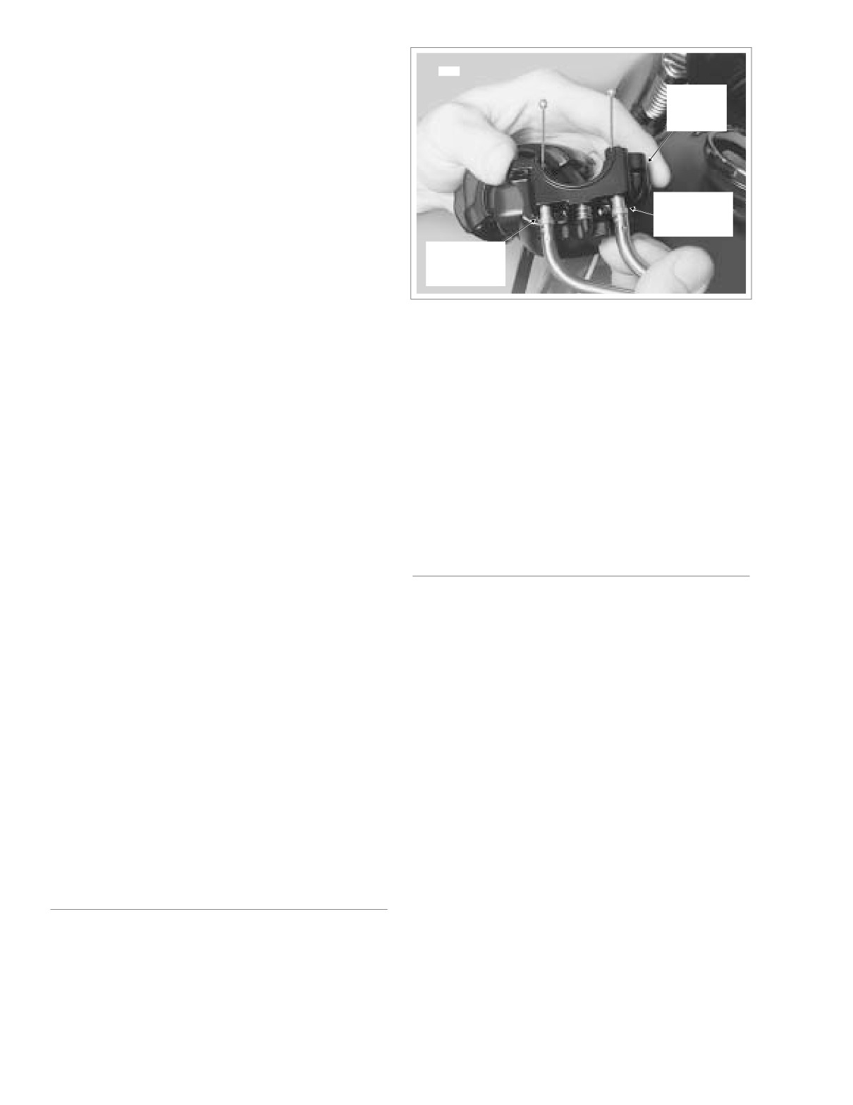
Figure 2-109. Install Throttle/Idle Cables
Place a drop of light oil on the retaining rings, if neces-
in Lower Switch Housing
sary. Remove the cables from the switch housing.
2.
Inspect the cables for damage or wear. Replace the
cables if frayed, kinked or bent.
CARBURETOR/INDUCTION MODULE SIDE
3.
Obtain tube of Lubit-8 Tufoil Chain and Cable Lube (HD
Part No. 94968-85TV- 1/4 fl. oz.). Insert pin of tube
1.
Remove the air cleaner and backplate. See Section 4.5
between throttle cable and cable housing. Squirt a few
AIR CLEANER, REMOVAL.
drops of lubricant into cable housing moving pin around
2.
Raise fuel tank to access cables in area of frame back-
cable OD. Repeat the procedure squirting a few drops
bone. For carbureted models, see Section 4.7 FUEL
between the idle cable and cable housing.
TANK (CARBURETED), PARTIAL REMOVAL, FLHT/C,
or FLHR/S. For fuel injected models, see Section 9.4
FUEL TANK (FUEL INJECTED), PARTIAL REMOVAL,
FLHT/C/U/I, FLTRI, or FLHR/C/S/I.
INSTALLATION
3.
Carbureted: Using a needle nose pliers, carefully pull
idle cable barrel from upper inboard hole in throttle
wheel. Pull throttle cable barrel from remaining hole.
THROTTLE SIDE
Release idle and throttle cables from guides in throttle
cable bracket. See Figure 2-107.
1.
Apply a light coating of graphite to the handlebar and
inside surface of the switch housings.
Induction Module: Using a needle nose pliers, carefully
pull idle cable barrel from upper hole in throttle wheel.
2.
Push the throttle and idle cables into the lower switch
Pull throttle cable barrel from lower hole. Using slots,
housing until they snap in place. See Figure 2-109. Pro-
release idle and throttle cables from guides in throttle
ceed as follows:
cable bracket. See Figure 2-111.
Note the different diameter inserts crimped into the end
4.
Free cables from J-clamp riveted to right side of frame
of the throttle and idle cable housings.
backbone.
Push the larger diameter insert (silver) on the throttle
5.
If present, remove screw (with flat washer) to release J-
cable housing into the larger hole in front of the tension
clamp from wellnut in right side of steering head.
adjuster screw.
Remove J-clamp from cables.
Push the smaller diameter insert (gold) on the idle cable
housing into the smaller hole at the rear of the tension
adjuster screw.
CLEANING AND INSPECTION
NOTE
To aid assembly, place a drop of light oil on the retaining
1. Clean all parts in a non-flammable cleaning solvent and
rings of the crimped inserts. Always replace the retaining
blow dry with compressed air.
rings if damaged or distorted.
2-90
2004 Touring: Chassis
HOME
8.
Position the brake lever/master cylinder assembly
Ferrule
Notch
Groove
inboard of the switch housing assembly engaging the
tab on the lower switch housing in the groove at the top
of the brake lever bracket.
9.
Align the holes in the handlebar clamp with those in the
master cylinder housing and start the lower screw (with
flat washer). Position for rider comfort. Beginning with
the top screw, tighten the screws to 60-80 in-lbs (6.8-9.0
Nm) torque using a T27 TORX drive head.
10. Using a T25 TORX drive head, tighten the lower and
upper switch housing screws to 35-45 in-lbs (4-5 Nm).
NOTE
Always tighten the lower switch housing screw first so that
any gap between the upper and lower housings is at the front
of the switch assembly.
Throttle
Grip
11. Remove the cardboard insert between the brake lever
and lever bracket.
12. Turn the Ignition/Light Key Switch to IGNITION and
Idle
Throttle
f1474x2x
apply brake lever to test operation of brake lamp.
Cable
Cable
Figure 2-110. Install Throttle/Idle Control Cables on
Throttle Control Grip
CARBURETOR/INDUCTION MODULE SIDE
1.
Route the throttle and idle cables as follows:
3. With the concave side facing upward, install the friction
shoe so that the pin hole is over the point of the adjuster
FLHT/C: Route the cables downward following the brake
screw.
line to the inner fairing. Pass the cables through the
inner fairing grommet and then loop them toward the
NOTE
rear along the right side of the steering head.
The friction shoe is a loose fit and may fall out or become dis-
FLHR/C: Route the cables downward following the right
lodged if the lower switch housing is turned upside down or
handlebar to the handlebar clamp shroud. Pass the
shaken.
cables through the opening in the shroud and then loop
them toward the rear along the right side of the steering
4. Slide the throttle control grip over the end of the right
handlebar until it bottoms against the closed end. Rotate
head. Capture cables in J-clamp and then start screw
the grip so that the ferrule notches are at the top. To pre-
(with flat washer) to fasten J-clamp to wellnut in right
vent binding, pull the grip back about 1/8 inch (3.2 mm).
side of steering head. Tighten screw to 9-18 in-lbs (1.0-
2.0 Nm).
5. Position the lower switch housing beneath the throttle
control grip. Install the brass ferrules onto the cables so
2.
Route the throttle and idle cables rearward along the
that the end fittings seat in the ferrule recess. Seat the
right side of the frame backbone. After passing through
ferrules in their respective notches on the throttle control
J-clamp riveted to frame backbone, route cables down-
grip. Verify that the cables are captured in the grooves
ward to carburetor/induction module.
molded into the grip. See Figure 2-110.
3.
Carbureted: Install sleeve on throttle cable housing into
6. Position the upper switch housing over the handlebar
shorter cable guide in throttle cable bracket. Drawing
and lower switch housing. Verify that the wire harness
throttle cable downward, fit barrel end into lower out-
conduit runs in the depression at the bottom of the han-
board hole in throttle wheel. Install sleeve and spring on
dlebar.
idle cable housing into longer cable guide inserting bar-
7. Start the upper and lower switch housing screws, but do
rel end into upper inboard hole in throttle wheel. See
not tighten.
Figure 2-107.
2004 Touring: Chassis
2-91
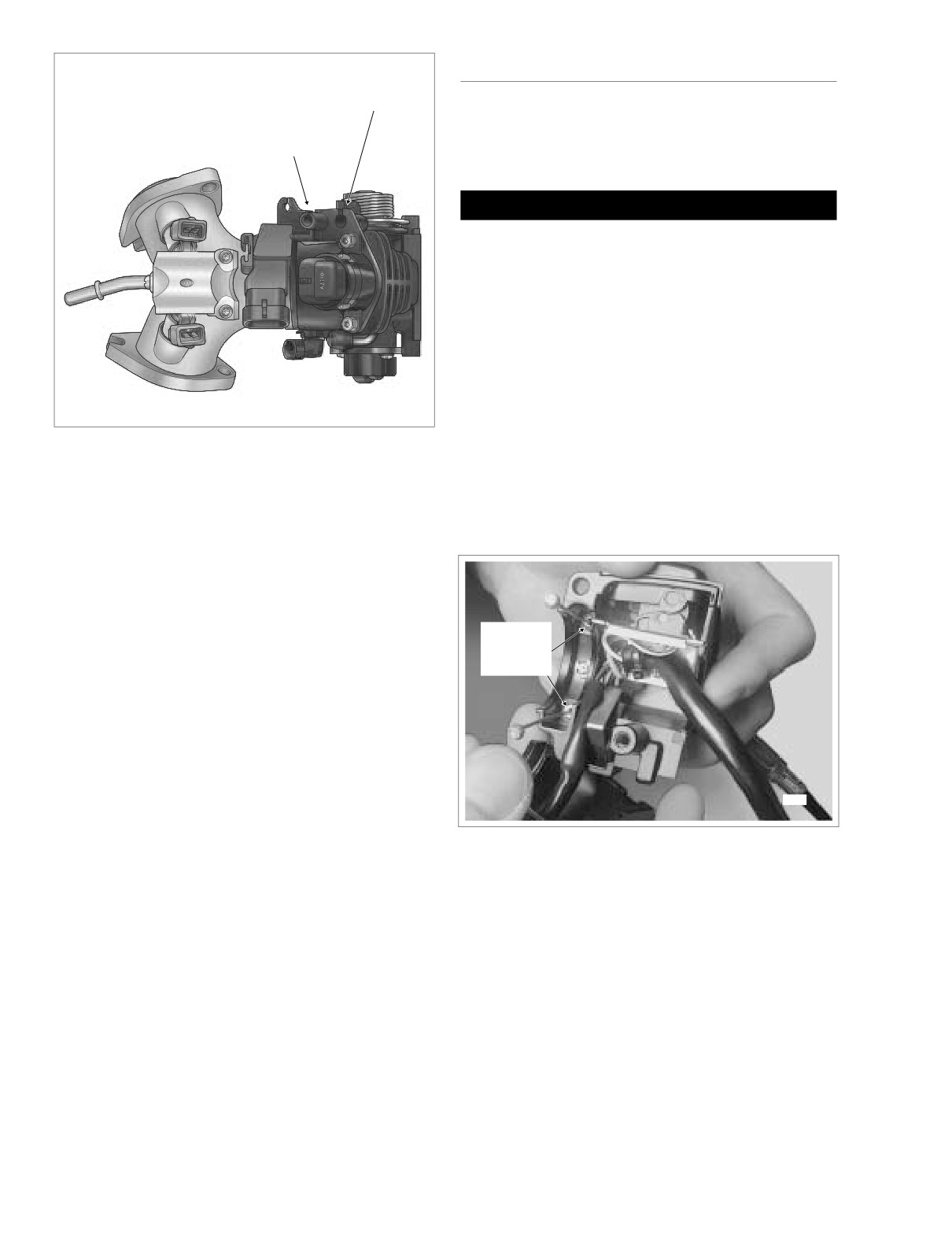
HOME
LUBRICATION
f2162x9x
Idle Cable
Guide
1. See REMOVAL, THROTTLE SIDE, in this section, steps
1-5.
Throttle Cable
Guide
2.
Move upper switch housing to the side in order to access
lower housing.
1CAUTION
Lubit-8 Tufoil Chain and Cable Lube contains detergents.
Keep out of reach of children. Contact with eyes may
result in minor or moderate injury.
3.
Obtain tube of Lubit-8 Tufoil Chain and Cable Lube (HD
Part No. 94968-85TV- 1/4 fl. oz.). Insert pin of tube
between throttle cable and cable housing inside lower
switch housing. Squeeze tube to squirt a quantity of
lubricant into cable housing moving pin around cable
OD. See Figure 2-112.
4.
Repeat the procedure squirting a quantity of lubricant
between the idle cable and cable housing.
Figure 2-111. Throttle Cable Assembly -
Induction Module Side
5.
See INSTALLATION, THROTTLE SIDE, in this section,
steps 3-12.
6.
Turn the Ignition/Light Key Switch to IGNITION and
Induction Module: Install sleeve on throttle cable hous-
apply brake lever to test operation of brake lamp.
ing into shorter cable guide at top of throttle cable
bracket. Drawing throttle cable downward, fit barrel end
into lower hole in throttle wheel. Install sleeve and spring
on idle cable housing into longer cable guide at bottom
of throttle cable bracket inserting barrel end into upper
hole in throttle wheel. See Figure 2-111.
Insert
4.
Tighten cables as necessary to keep barrel ends from
Lubricant
Here
dislodging. Verify that cables are seated in channel of
throttle wheel. Verify operation by turning throttle grip
and observing cable action. Adjust throttle cables as
described under ADJUSTMENT.
5.
Install fuel tank. For carbureted models, see Section 4.7
FUEL TANK (CARBURETED), INSTALLATION (AFTER
PARTIAL REMOVAL), FLHT/C, or FLHR/S. For fuel
injected models, see Section 9.4 FUEL TANK (FUEL
7958
INJECTED), INSTALLATION
(AFTER PARTIAL
REMOVAL), FLHT/C/U/I, FLTRI, or FLHR/C/S/I.
Figure 2-112. Right Handlebar Lower Switch Housing
6.
Install the air cleaner assembly. See Section 4.5 AIR
CLEANER, INSTALLATION.
2-92
2004 Touring: Chassis
HOME
CLUTCH CABLE
2.22
ADJUSTMENT
f1140axx
Flat
Screw
Washer
See Section 6.3 CLUTCH, ADJUSTMENT.
Pivot Pin
Clutch Cable
Clutch
Lever
Handlebar
REMOVAL
Bracket
Clamp
Bushing
1.
Remove maxi-fuse. See Section 8.3 SYSTEM FUSES,
Hand Lever
MAXI-FUSE, REMOVAL.
Retaining
Ring
2.
To access the clutch release cover assembly, remove
right side exhaust system. See Section 3.7 REMOVING
Anchor
Pin
ENGINE FROM CHASSIS, steps 3-9.
Rubber Boot
Anti-Rattle
3.
Remove the magnetic drain plug at the bottom right side
Spring
of the oil pan and drain the transmission lubricant into a
and Screw
O-Ring
suitable container. Remove the filler plug/dipstick.
4.
Slide rubber boot off clutch cable adjuster. Holding cable
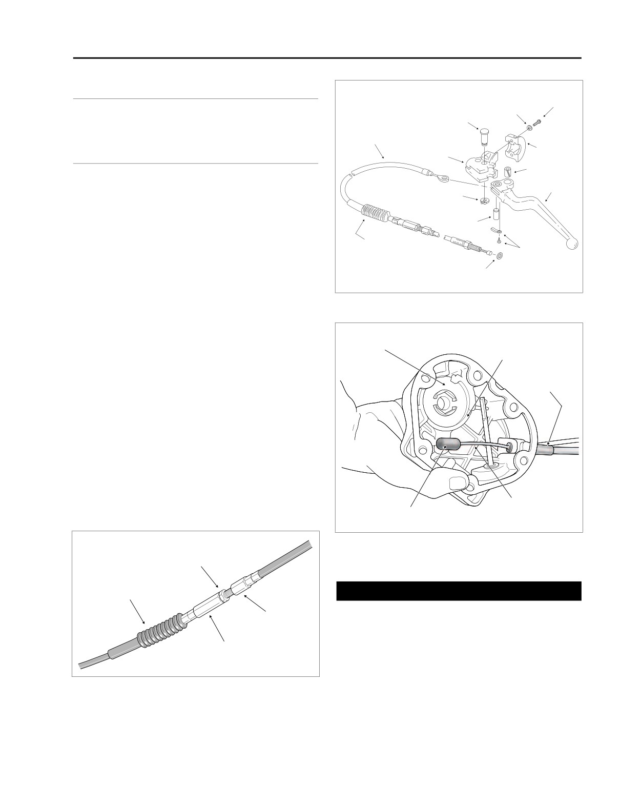
Figure 2-114. Clutch Hand Lever Assembly
adjuster with 1/2 inch wrench, loosen jam nut using 9/16
inch wrench. Back jam nut away from cable adjuster.
Move adjuster toward jam nut to introduce free play at
Inner
hand lever. See Figure 2-113.
Retaining
Ramp
Ring
5.
Remove retaining ring from pivot pin groove at bottom of
clutch lever bracket. Remove pivot pin.
Cable
Fitting
6.
Remove clutch hand lever from clutch lever bracket. If
necessary, use a T27 TORX drive head and remove two
screws (with flat washers) to release handelbar clamp
from clutch lever bracket.
7.
Remove anchor pin and clutch cable eyelet from clutch
hand lever. See Figure 2-114.
8.
Remove six socket head screws and washers to free
clutch release cover from transmission case. Remove
and discard gasket. See Figure 2-115.
Clutch Cable
Coupling
f1896x7x
Figure 2-115. Clutch Release Cover Assembly
f1440x6x
Jam
Nut
Rubber
Boot
1WARNING
Always wear proper eye protection when removing re-
Cable
End
taining rings. Use the correct retaining ring pliers. Verify
that the tips of the pliers are not damaged or excessively
worn. Slippage may propel the ring with enough force to
Cable
Adjuster
cause eye injury.
9.
Remove retaining ring securing ball and ramp mech-
Figure 2-113. Clutch Cable Adjuster Mechanism
anism to clutch release cover.
2004 Touring: Chassis
2-93
HOME
10. Lift inner ramp out of clutch release cover and turn the
assembly over so that ball sockets are facing outboard.
Right Frame
f1472b2x
Remove hook of ramp from button on coupling. Remove
Downtube
coupling from clutch cable end.
11. Remove balls from outer ramp sockets. Remove outer
ramp from clutch release cover.
12. Unscrew the cable fitting from the clutch release cover.
Remove clutch cable and fitting.
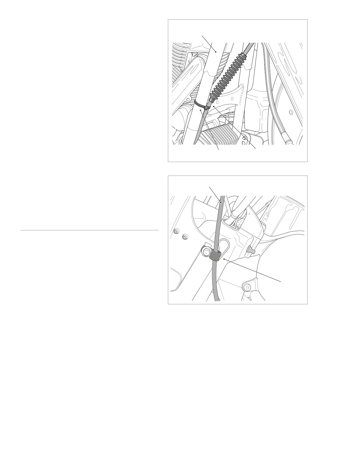
13. Cut cable strap in hole of crossbrace to free clutch cable
from right frame downtube. See Figure 2-116. Continue
as follows:
FLHR/C/S: Remove T40 TORX screw with flat washer
(FLHRS) or acorn nut (FLHR/C) to release clutch cable
from P-clamp fastened to upper fork bracket. See Figure
2-117.
FLTR: Release clutch cable from cable clip anchored in
hole on left side of instrument nacelle.
FLHT/C/U: Remove the outer fairing. See Section 2.29
UPPER FAIRING/WINDSHIELD (FLHT/C/U), OUTER
FAIRING/WINDSHIELD, REMOVAL. Cut cable strap to
Clutch Cable
Cable Strap
release clutch cable from left fairing bracket. See Figure
2-118.
Figure 2-116. Clutch Cable Routing (Right Side View)
14. Remove clutch cable from motorcycle.
NOTE
Clutch Cable
f2257x2x
If ball and ramp or throwout bearing and clutch pushrod need
service, see Section 7.5 CLUTCH RELEASE COVER.
INSTALLATION
1. See Figure 2-114. Insert clutch cable eyelet into groove
of clutch hand lever aligning eyelet with hole without
bushing. Insert anchor pin through lever and eyelet.
2. Insert lever into groove of clutch lever bracket fitting
sleeve at end of cable housing into bore on inboard side
of bracket.
3. Align hole in hand lever with hole in bracket and install
Clamp
pivot pin. Install retaining ring in pivot pin groove.
4. If removed, use a T27 TORX drive head and install two
screws (with flat washers) to secure handelbar clamp to
clutch lever bracket. See Figure 2-114. Starting with the
Figure 2-117. Clutch Cable Routing - FLHR/C
top screw, tighten screws to 60-80 in-lbs (6.8-9.0 Nm).
(Left Side View)
5. Start clutch cable routing as follows:
FLHR/C/S: Capture clutch cable in P-clamp and fasten
FLHT/C/U: Feed clutch cable through grommet on left
to upper fork bracket using T40 TORX screw with flat
side of inner fairing. Route cable on inboard side of left
washer (FLHRS) or acorn nut (FLHR/C). Orient P-clamp
fairing bracket between upper and lower wings of radio
as shown in Figure 2-117. On left side of steering head,
(or storage box) support bracket. Cable strap clutch
run cable downward between engine guard and front of
cable to left fairing bracket using oblong hole at this loca-
left frame downtube.
tion. See Figure 2-118. Run cable downward along left
FLTR: Capture clutch cable in cable clip and anchor clip
side of steering head, and then between engine guard
in hole on left side of instrument nacelle. Run cable for-
and front of left frame downtube. Install the outer fairing.
ward and then rearward beneath instrument nacelle fol-
See Section
2.29 UPPER FAIRING/WINDSHIELD
lowing left side of steering head. Run cable downward
(FLHT/C/U), OUTER FAIRING/WINDSHIELD, INSTAL-
between engine guard and front of left frame downtube.
LATION.
2-94
2004 Touring: Chassis
HOME
12. Install the retaining ring so that the opening is to the right
9421
of the outer ramp tang slot in the clutch release cover.
13. Verify that the two locating dowels are in place on the
right side of the transmission case. Hang a new gasket
on the dowels.
14. Holding the clutch release cover in position, install six
socket head screws. Tighten screws to 120-144 in-lbs
(13.6-16.3 Nm).
15. Tighten clutch cable fitting to 36-60 in-lbs (4-7 Nm).
16. Check the O-ring on the transmission drain plug for
tears, cuts or general deterioration. Replace as nec-
Cable
essary.
Strap
CAUTION
Do not overtighten filler plugs or drain plugs. Overtight-
Figure 2-118. Secure Clutch Cable to Fairing Bracket
ening plugs can cause leaks.
17. Install transmission the drain plug. Tighten the plug to
6.
Complete clutch cable routing as follows:
14-21 ft-lbs (19-28 Nm).
All Models: Continue downward progression while
crossing to right side of motorcycle and then run cable
between outboard side of voltage regulator and inboard
side of right frame downtube. Threading cable strap
8496
Clutch
through hole in crossbrace, secure clutch cable to down-
Release
tube as shown in Figure 2-116. Following inboard side of
Cover
frame downtube, route cable between bottom of cam
cover and top of lower frame tube to area of clutch
release cover.
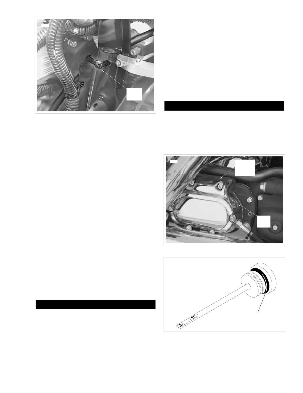
7.
Inspect cable fitting O-ring and replace if damaged or
deformed. Install clutch cable fitting into clutch release
cover. See Figure 2-115. Do not tighten cable fitting at
this time.
Filler
8.
Place outer ramp in clutch release cover recess with
Plug
tang in cover slot.
9.
Apply a multi-purpose grease to the balls and outer
ramp sockets. Place a ball in each of three outer ramp
sockets.
Figure 2-119. Transmission Case (Right Side)
10.
Hold coupling with button facing outboard. Place cable
end in recess of coupling. With ball sockets facing out-
OMF50
board, place hook of inner ramp on button of couplng.
Holding inner ramp and coupling together, turn the
assembly over.
11.
Place inner ramp (ball socket side down) over balls in
outer ramp sockets.
1WARNING
Always wear proper eye protection when installing re-
O-Ring
taining rings. Use the correct retaining ring pliers. Verify
that the tips of the pliers are not damaged or excessively
worn. Slippage may propel the ring with enough force to
cause eye injury.
Figure 2-120. Transmission Lubricant Filler Plug/Dipstick
2004 Touring: Chassis
2-95
HOME
18. Remove the filler plug from the clutch release cover, if
21. Adjust the clutch cable. See Section
6.3 CLUTCH,
installed. See Figure 2-119. Check the O-ring for tears,
ADJUSTMENT.
cuts or general deterioration. Replace as necessary.
22. Install right side exhaust system. See Section
3.8
See Figure 2-120.
INSTALLING ENGINE IN CHASSIS, steps 46-52.
19. Fill the transmission with
20-24 oz. (590-710 ml) of
23. Install maxi-fuse. See Section
8.3 SYSTEM FUSES,
transmission lubricant or until the lubricant level on the
MAXI-FUSE, INSTALLATION.
dipstick of the filler plug is at the F(ULL) mark with the
motorcycle in a level, upright position and the filler plug
resting on the threads. Use only Harley-Davidson
TRANSMISSION LUBRICANT, Part No.
99892-84
(quart) or Part No. 99891-84 (gallon).
20. Install the transmission filler plug/dipstick in the clutch
release cover. Tighten the plug to 25-75 in-lbs (2.8-8.5
Nm).
2-96
2004 Touring: Chassis
HOME
HANDLEBARS
2.23
10. If necessary, adjust left and right handlebar switch con-
HANDLEBAR ADJUSTMENT
trols as follows:
a. Using a T27 TORX drive head, loosen the two
1. Remove maxi-fuse. See Section 8.3 SYSTEM FUSES,
screws securing the handlebar clamp to the clutch
MAXI-FUSE, REMOVAL.
lever bracket
(left) or master cylinder housing
2. FLHR/C/S: Remove the handlebar clamp shroud. See
(right).
Section
2.31 WINDSHIELD/HEADLAMP NACELLE
b. Position switch controls for rider posture and com-
(FLHR/C/S), NACELLE REMOVAL (FLHR/C), steps 1-
fort.
11, or NACELLE REMOVAL (FLHRS), steps 1-7.
c. Beginning with the top screw, tighten the screws to
FLTR: Remove the instrument bezel. See Section 2.30
60-80 in-lbs (6.8-9.0 Nm).
UPPER FAIRING/WINDSHIELD
(FLTR), BEZEL,
REMOVAL.
11. Install maxi-fuse. See Section
8.3 SYSTEM FUSES,
MAXI-FUSE, INSTALLATION.
FLHT/C/U: Remove the fairing cap. See Section 2.29
UPPER FAIRING/WINDSHIELD (FLHT/C/U), FAIRING
CAP, REMOVAL.
HANDLEBAR REMOVAL
3. Loosen rear screws on the upper handlebar clamps. On
FLTR models, loosen the front screws instead.
1.
Remove maxi-fuse. See Section 8.3 SYSTEM FUSES,
4. Position handlebars for rider posture and comfort.
MAXI-FUSE, REMOVAL.
5. To be sure that the handlebars are centered, verify that
2.
Place blanket or protective cover over front of fuel tank to
the knurled area on the outboard side of the left side
protect against scratches or other damage.
handlebar clamp is equal to that on the right side.
3. FLHR/C/S: Remove the handlebar clamp shroud. See
Section
2.31 WINDSHIELD/HEADLAMP NACELLE
6. Snug upper handlebar clamp screws.
(FLHR/C/S), NACELLE REMOVAL (FLHR/C), steps 1-
11, or NACELLE REMOVAL (FLHRS), steps 1-7.
1WARNING
FLTR: Remove the instrument nacelle. See Section 2.30
Improperly aligned handlebars can contact the fuel tank
UPPER FAIRING/WINDSHIELD (FLTR), INSTRUMENT
when turned to the left or right fork stops. Contact with
NACELLE, REMOVAL.
the fuel tank while riding can cause loss of vehicle con-
FLHT/C/U: Remove the fairing cap. See Section 2.29
trol resulting in death or serious injury.
UPPER FAIRING/WINDSHIELD (FLHT/C/U), FAIRING
CAP, REMOVAL. Remove the radio (or storage box).
7.
Slowly turn handlebars to the full right fork stop and then
See Section 8.31 PREMIUM SOUND SYSTEM (FLHTC/
the full left fork stop to be sure there is no contact with
U, FLTR), RADIO (FLHTC/U), REMOVAL, steps 3-7.
the fuel tank. If contact occurs and handlebars are prop-
erly aligned, raise handlebars as necessary until the
4.
Remove the left and right handlebar switch controls. See
proper clearance is obtained.
Section 8.21 HANDLEBAR SWITCHES, REMOVAL.
8. Tighten the upper handlebar clamp screws to 12-16 ft-
5.
Remove upper handlebar clamp screws (with flat wash-
lbs (16.3-21.7 Nm).
ers). Remove upper handlebar clamps and handlebar.
9. FLHR/C/S: Install the handlebar clamp shroud. See
Section
2.31 WINDSHIELD/HEADLAMP NACELLE
(FLHR/C/S), NACELLE INSTALLATION
(FLHR/C),
HANDLEBAR INSTALLATION
steps
3-15, or NACELLE INSTALLATION (FLHRS),
steps 5-13.
1. Place new handlebars on lower handlebar clamps.
FLTR: Install the instrument bezel. See Section 2.30
Install upper handlebar clamps and loosely install clamp
UPPER FAIRING/WINDSHIELD
(FLTR), BEZEL,
screws (with flat washers).
INSTALLATION.
2. To be sure that the handlebars are centered, verify that
FLHT/C/U: Install the fairing cap. See Section
2.29
the knurled area on the outboard side of the left side
UPPER FAIRING/WINDSHIELD (FLHT/C/U), FAIRING
handlebar clamp is equal to that on the right side.
CAP, INSTALLATION.
3. Snug upper handlebar clamp screws.
2004 Touring: Chassis
2-97
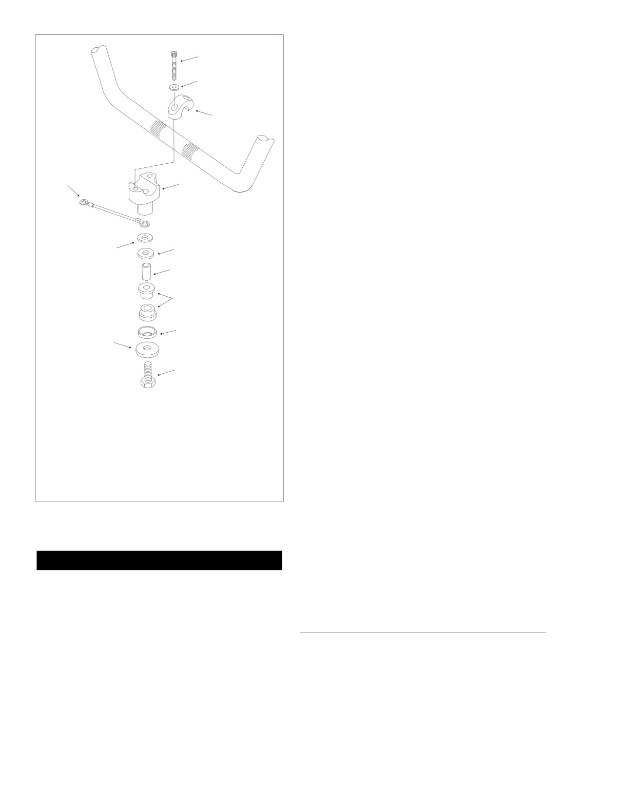
HOME
5. Tighten upper handlebar clamp screws as follows:
f2056x2x
1
a. Tighten front screws until upper and lower handle-
bar clamps make contact.
2
b. Tighten rear screws to 12-16 ft-lbs (16.3-21.7 Nm).
c. Tighten front screws to 12-16 ft-lbs (16.3-21.7 Nm).
3
NOTE
A slight gap will exist between the upper and lower clamps at
the rear of the handlebars after tightening.
6.
Install the left hand grip. See LEFT HAND GRIP,
INSTALLATION, in this section.
*9
4
7.
Install the left and right handlebar switch controls. See
Section
8.21 HANDLEBAR SWITCHES, INSTALLA-
TION.
8.
FLHR/C/S: Install the handlebar clamp shroud. See
5
Section
2.31 WINDSHIELD/HEADLAMP NACELLE
**10
(FLHR/C/S), NACELLE INSTALLATION
(FLHR/C),
6
steps
3-15, or NACELLE INSTALLATION (FLHRS),
steps 5-13.
7
FLTR: Install the instrument nacelle. See Section 2.30
UPPER FAIRING/WINDSHIELD (FLTR), INSTRUMENT
NACELLE, INSTALLATION.
5
**11
FLHT/C/U: Install the fairing cap. See Section
2.29
UPPER FAIRING/WINDSHIELD (FLHT/C/U), FAIRING
CAP, INSTALLATION. Install the radio (or storage box).
8
See Section 8.31 PREMIUM SOUND SYSTEM (FLHTC/
U, FLTR), RADIO (FLHTC/U), INSTALLATION, steps 1-
6.
1.
Screw
2.
Flat washer
*LEFT CLAMP ONLY
9.
Install maxi-fuse. See Section
8.3 SYSTEM FUSES,
3.
Upper clamp
MAXI-FUSE, INSTALLATION.
9. Ground cable
4.
Lower clamp
10.
Turn the ignition/light key switch to IGNITION and test
5.
Cup washer
**RIGHT CLAMP ONLY
each handlebar switch for proper operation.
6.
Spacer
7.
Rubber bushing
10. Flat washer
11.
Apply front brake hand lever to test operation of brake
8.
Bolt
11. Large flat washer
lamp.
12.
Adjust idle and throttle control cables as follows:
Figure 2-121. Handlebar Clamp Assemblies
Non-Cruise: See Section 2.21 THROTTLE CABLES
(NON-CRUISE), ADJUSTMENT.
Cruise Equipped: See Section 8.30 CRUISE CON-
1WARNING
TROL (FLHRC, FLTR, FLHTCU), CABLE ADJUST-
MENT.
Improperly aligned handlebars can contact the fuel tank
when turned to the left or right fork stops. Contact with
the fuel tank while riding can cause loss of vehicle con-
trol resulting in death or serious injury.
LEFT HAND GRIP
4. Slowly turn handlebars to the full right fork stop and then
the full left fork stop to be sure there is no contact with
REMOVAL
the fuel tank. If contact occurs and handlebars are prop-
erly aligned, raise handlebars as necessary until the
1. Remove the left handlebar switch controls. See Section
proper clearance is obtained.
8.21 HANDLEBAR SWITCHES, REMOVAL.
2-98
2004 Touring: Chassis
HOME
2. Use a sharp blade to carefully cut rubber and then peel
Right Side
off handlebar.
3.
Holding lower handlebar clamp to prevent rotation, turn
3. Thoroughly clean handlebar to remove all residual adhe-
bolt at bottom of upper fork bracket until free.
sive.
4. Remove lower handlebar clamp, flat washer and cup
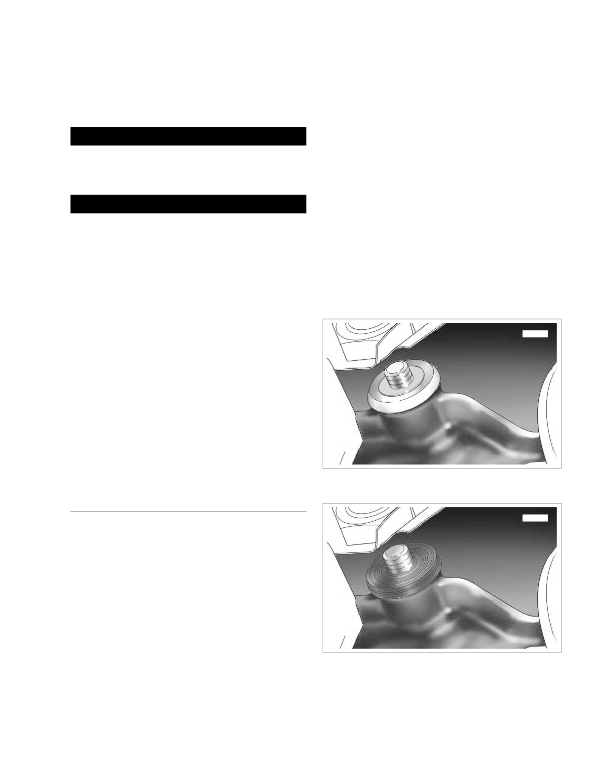
washer at top of upper fork bracket. See Figure 2-122.
INSTALLATION
5.
Pull bushing from fork bracket bore and discard. See
Figure 2-123.
1WARNING
6.
Moving to bottom of upper fork bracket, remove bolt,
HARLEY-DAVIDSON ADHESIVE contains METHYL
large flat washer and cup washer. See Figure 2-124.
ETHYL KETONE, a chemical known to the State of Cali-
7.
Pull bushing and spacer from fork bracket bore. Remove
fornia to cause cancer or other reproductive harm.
spacer from bushing. See Figure 2-125. Discard bush-
ing.
1WARNING
Use HARLEY-DAVIDSON ADHESIVE in well ventilated
Left Side
areas only. Vapors are flammable and can be harmful to
breath. Avoid contact with eyes, mucous membranes, or
8.
Holding lower handlebar clamp to prevent rotation, turn
prolonged contact with skin. Keep out of reach of chil-
bolt at bottom of upper fork bracket until free.
dren.
9.
Remove lower handlebar clamp, ground wire ring termi-
1. Obtain a new left hand grip and HARLEY-DAVIDSON
nal and cup washer at top of upper fork bracket.
ADHESIVE (Part No. 99839-95). Apply a coat of the
adhesive to the inside surface of the grip one inch (25.4
mm) from the open end. Apply a coat to the end of the
handlebar.
f2077x2x
2.
Immediately push grip completely onto end of handlebar
using a twisting motion. Do not hesitate when installing
grip or adhesive may dry before installation is complete.
NOTE
If the left hand grip is patterned, align it with the pattern on
the right grip with the throttle in the fully closed position.
3.
Let 6-8 hours elapse (at 70° F.) to allow adhesive to fully
cure.
4. Install the left handlebar switch controls. See Section
8.21 HANDLEBAR SWITCHES, INSTALLATION.
Figure 2-122. Remove Flat Washer and
Upper Cup Washer (Right Side)
RUBBER MOUNTS
f2076x2x
NOTE
For complete disassembly of the handlebar clamp assem-
blies and/or to replace the rubber mounts, proceed as fol-
lows.
REMOVAL
General
1.
Turn fork to left fork stop and loosen right side bolt at
bottom of upper fork bracket. Turn fork to right fork stop
and loosen left side bolt at bottom of upper fork bracket.
2.
Remove handlebars. See HANDLEBAR REMOVAL in
Figure 2-123. Remove Upper Bushing (Right Side)
this section.
2004 Touring: Chassis
2-99
HOME
5. Install cup washer over threaded end of bolt fitting con-
f2058x2x
cave side over collar of bushing. Install flat washer. See
Figure 2-122.
6. Apply two or three drops of Loctite Medium Strength
Threadlocker 243 (blue) to threads of bolt and start lower
handlebar clamp. Holding clamp to prevent rotation, turn
bolt at bottom of upper fork bracket until snug.
Left Side
7.
Insert spacer into new bushing until flush with outboard
side of collar. See Figure 2-125.
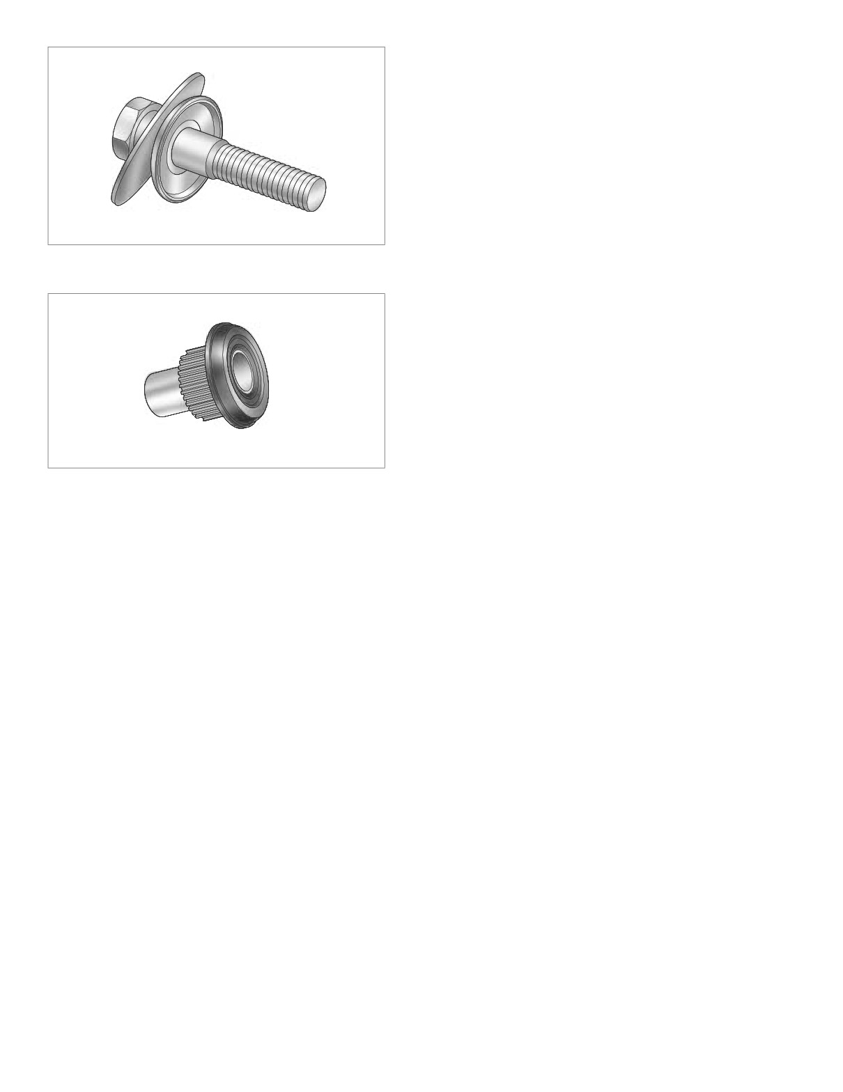
Figure 2-124. Remove Bolt, Large Washer
and Lower Cup Washer (Right Side)
8.
Insert bushing into bore at bottom of upper fork bracket
fitting collar of bushing over lip of boss.
f2057x2x
9.
Install cup washer on bolt. Insert bolt into bushing fitting
concave side of cup washer over collar of bushing.
10. Moving to top of upper fork bracket, insert bushing into
bore fitting collar of bushing over lip of boss. See Figure
2-123.
11. Install cup washer over threaded end of bolt fitting con-
cave side over collar of bushing. Install ground wire ring
terminal.
12. Apply two or three drops of Loctite Medium Strength
Threadlocker 243 (blue) to threads of bolt and start lower
Figure 2-125. Remove Spacer From Lower Bushing
handlebar clamp. Holding clamp to prevent rotation, turn
bolt at bottom of upper fork bracket until snug.
General
10. Pull bushing from fork bracket bore and discard. See
Figure 2-123.
13. Install handlebars and upper handlebar clamps. See
11. Moving to bottom of upper fork bracket, remove bolt and
HANDLEBAR INSTALLATION in this section, steps 1-5.
cup washer.
14. Turn fork to left fork stop and tighten right side bolt at
12. Pull bushing and spacer from fork bracket bore. Remove
bottom of upper fork bracket to 30-40 ft-lbs (40.7-54.2
spacer from bushing. See Figure 2-125. Discard bush-
Nm). Turn fork to right fork stop and tighten left side bolt
ing.
to the same torque value.
15. Complete assembly of motorcycle. See HANDLEBAR
INSTALLATION in this section, steps 7-12.
INSTALLATION
Right Side
1.
Insert spacer into new bushing until flush with outboard
side of collar. See Figure 2-125.
2.
Insert bushing into bore at bottom of upper fork bracket
fitting collar of bushing over lip of boss.
3.
Install large flat washer and cup washer on bolt. See Fig-
ure 2-124. Insert bolt into bushing fitting concave side of
cup washer over collar of bushing.
4.
Moving to top of upper fork bracket, insert bushing into
bore fitting collar of bushing over lip of boss. See Figure
2-123.
2-100
2004 Touring: Chassis
HOME
SEAT
2.24
FLHR
Seat
Bottom
Tongue
REMOVAL
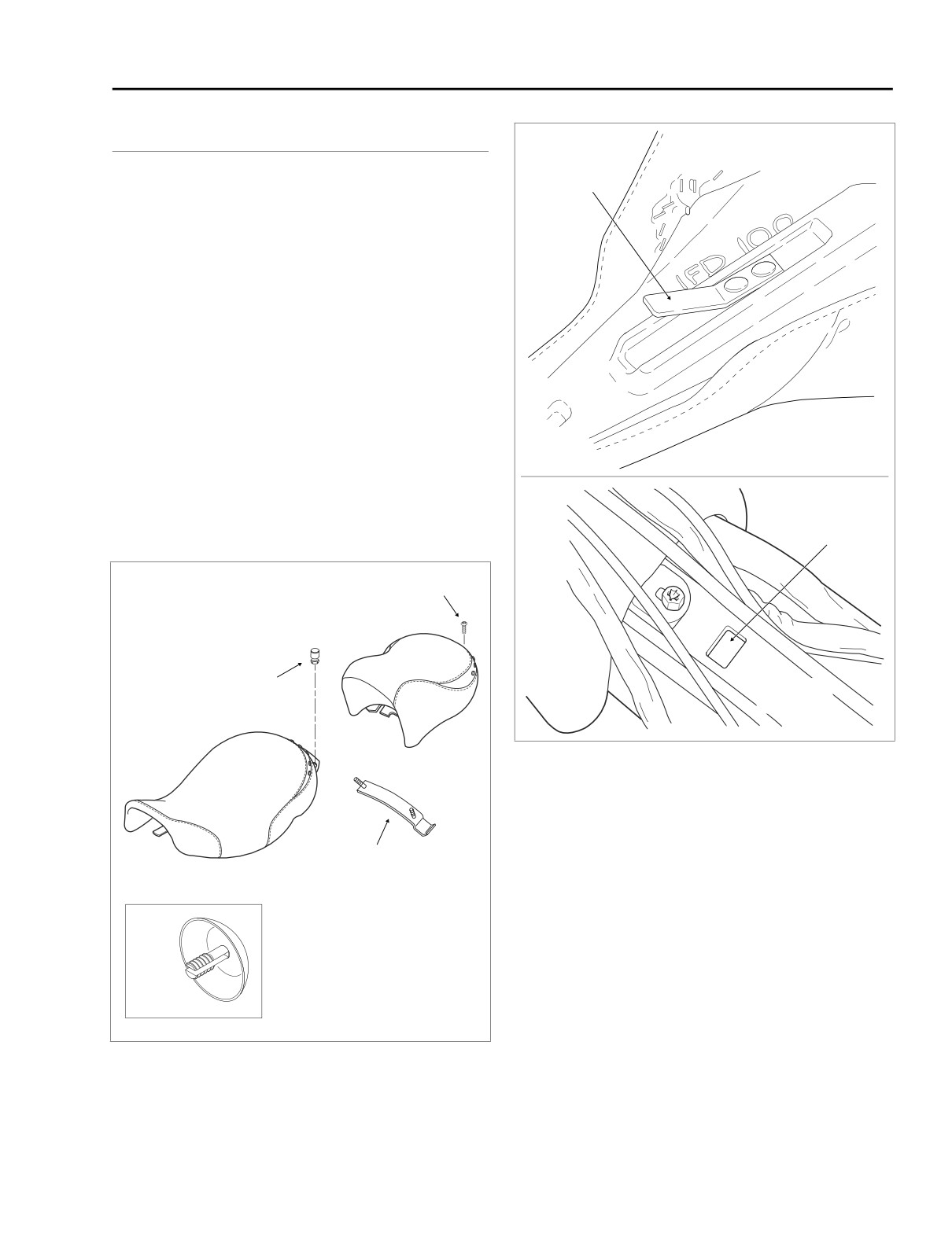
1. Remove Phillips screw to detach passenger seat mount-
ing bracket from top of rear fender. See Figure 2-126.
Slightly lift up back of passenger seat and carefully slide
toward rear of vehicle to detach from front seat mounting
bracket nuts.
NOTE
The FLHR seat can be converted to a solo seat by removal of
the passenger section. When the solo seat configuration is
desired, turn the passenger seat upside down and locate the
chrome plug pressed into the seat frame hole. See inset of
Figure 2-126. Remove the plug and press into the seat reten-
tion nut hole using finger pressure only.
2.
Using the 5/8 hex, remove two nuts from studs to free
f1416x2x
front seat mounting bracket from rear fender.
f2171x2x
3.
Push front seat rearward to free tongue
from slot in
frame backbone. See Figure 2-127.
Slot
f1091d2x
Screw
Passenger
Seat
Nut
Frame
Backbone
Front Seat
Figure 2-127. Seat Mounting
INSTALLATION
1.
Position front seat on frame with mounting bracket at
Stud Plate
rear.
2.
Firmly push front of seat downward and rearward until
tongue engages slot in frame backbone. See Figure 2-
127. Push seat forward until studs are centered in slots
of mounting bracket.
3.
Using the 5/8 hex, install two nuts on studs to secure
Passenger Seat
front seat mounting bracket to rear fender.
f1456x2x
Retention Nut Plug
4.
Install passenger seat fitting slots on passenger seat
front mounting bracket between rounded caps and hex
Figure 2-126. Seat Assembly - FLHR
of front seat mounting bracket nuts.
2004 Touring: Chassis
2-101