Harley Davidson 2004 Touring Models. Service Manual - page 23
HOME
2.
With the tang on the same side as the square shaped
f2250x8x
opening in the mating end of the connector housing,
feed terminal into wire end of connector housing until it
“clicks” in place.
3.
Verify that terminal will not back out of the chamber. A
slight tug on the cable will confirm that it is locked.
4.
Rotate the hinged secondary lock inward until latches
fully engage tabs on both sides of connector housing.
5.
Mate pin and socket halves of connector.
6.
Install new anchored cable strap in lower hole on left
side of frame crossmember (in front of battery box).
Tighten cable strap to capture conduit of both accessory
connector and B+ connector approximately one inch
from connector housings. See Figure 8-41.
7.
Place battery in battery box, terminal side forward.
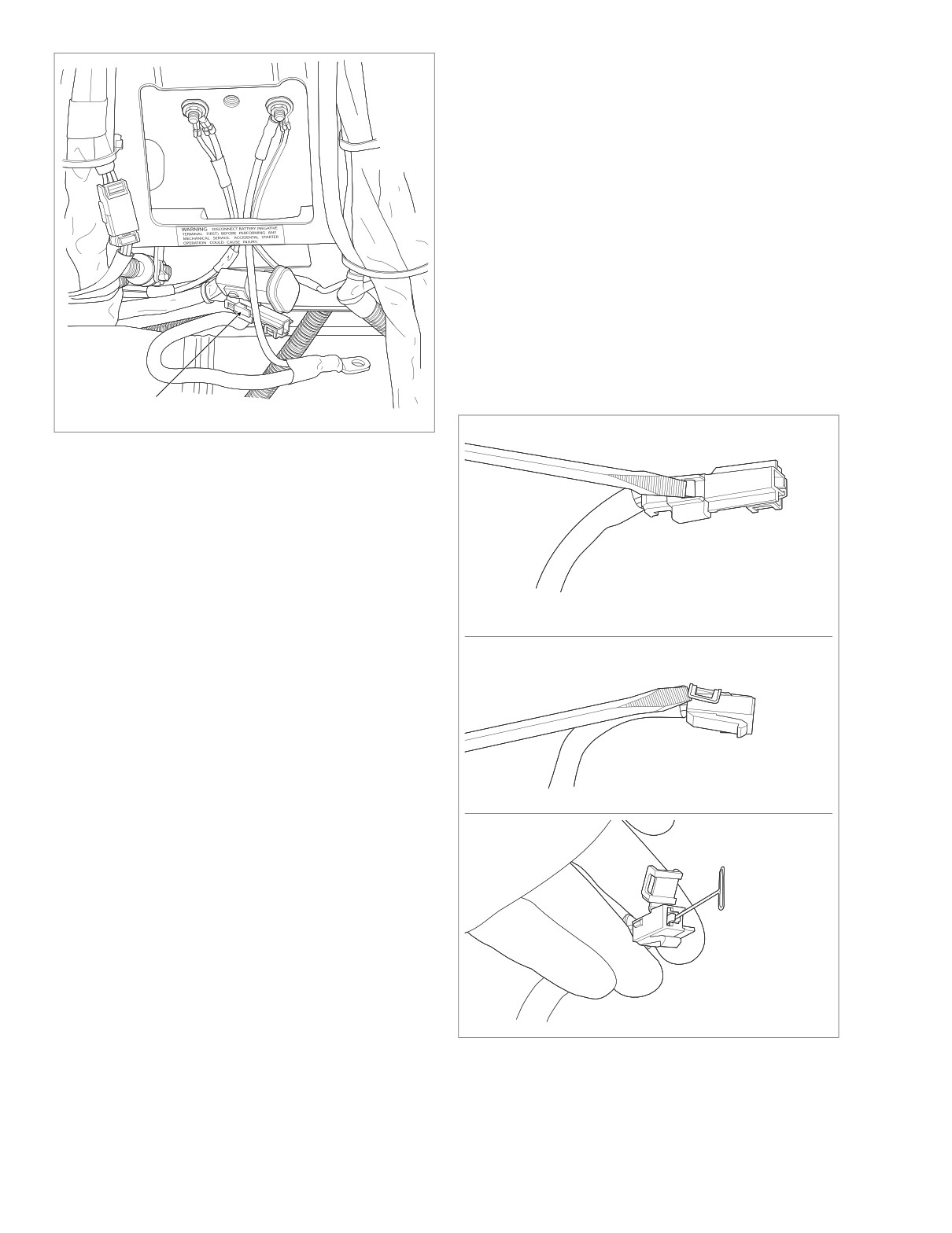
B+ Connector
Figure 8-40. Remove Seat
3.
Unthread bolt and remove battery positive cable (red)
from battery positive (+) terminal.
4.
Using a T40 TORX drive head, loosen bolt to move lip of
hold-down clamp off edge of battery. Remove battery
from battery box.
5.
Cut anchored cable strap to release accessory connec-
f2258x8x
A
tor and B+ connector from left side of frame crossmem-
ber (in front of battery box). See Figure 8-41.
6.
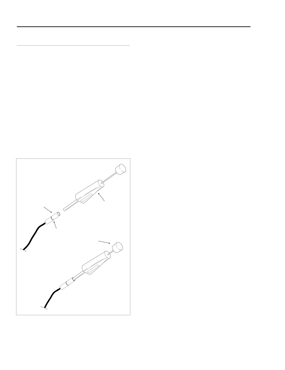
Using small flat blade screwdriver, depress button on pin
housing (red wire) side of the connector and pull apart
the pin and socket halves. See A of Figure 8-41.
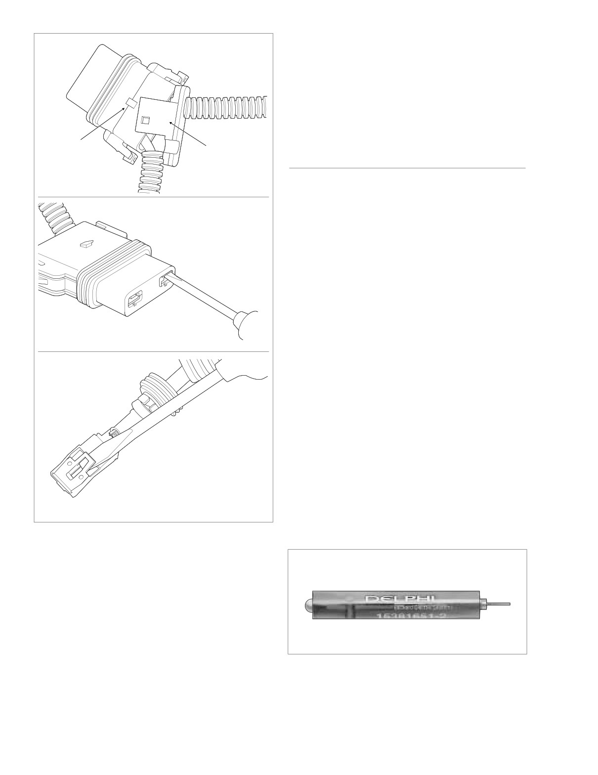
7.
Bend back the latch slightly and free one side of second-
ary lock, then repeat the step to release the other side.
Rotate the secondary lock outward on hinge to access
terminal in chamber of connector housing. See B of Fig-
ure 8-41.
f2259x8x
B
8.
On the mating end of the connector, note the tang in the
square shaped opening centered next to the terminal.
Gently insert the point of a stick pin or large safety pin
into the opening between the tang and the chamber wall
until it stops. Pivot the end of the pin toward the terminal
body to depress the tang. Remove the pin and then pull
terminal out wire end of connector housing. See C of
Figure 8-41.
9.
If necessary, crimp new terminals on wires. See Crimp-
ing Instructions at the end of this section.
f2260x8x
C
Assembly
1. Carefully bend the tang outward away from the terminal
Figure 8-41. Remove Socket Terminal
body.
8-30
2004 Touring: Wiring
HOME
Assembly
1WARNING
NOTE
Always connect the positive battery cable first. If the
For wire location purposes, alpha characters are molded into
positive cable should contact ground with the negative
the secondary locks of each connector housing.
cable installed, the resulting sparks may cause a battery
explosion, which could result in death or serious injury.
1.
Using a thin flat blade, like that on an X-Acto knife, care-
8. Insert bolt through battery positive cable
(red) into
fully bend the tang outward away from the terminal body.
threaded hole of battery positive (+) terminal. Tighten
2.
With the tang facing the chamber wall, push the lead into
bolt to 60-96 in-lbs (6.8-10.9 Nm).
the chamber at the wire end of the connector. A click is
9. Insert bolt through battery negative cable (black) into
heard when the terminal is properly seated.
threaded hole of battery negative (-) terminal. Tighten
3.
Gently tug on the wire end to verify that the terminal is
bolt to 60-96 in-lbs (6.8-10.9 Nm).
locked in place and will not back out of the chamber.
10. Rotate hold-down clamp so that the lip (with rubber pad)
rests on the edge of the battery. Using a T40 TORX drive
4.
Rotate the hinged secondary lock inward until tabs fully
head, tighten the clamp bolt to 15-20 ft-lbs (20-27 Nm).
engage latches on both sides of connector.
11. Install seat.
5.
Push the pin and socket halves of the connector
together until the latches “click.”
6.
Install connector on barbed anchor or other retaining
device, if present.
630 METRI-PACK SERIES
General
800 METRI-PACK SERIES
Use these instructions to service the following connectors:
● Main to Interconnect Harness [15]
General
● Ignition Light/Key Switch [33]
Use the following instructions to service the maxi-fuse holder.
Disassembly
1. Remove connector from barbed anchor or other retain-
Disassembly
ing device, if present.
2. Bend back the external latch slightly and separate pin
1. Remove maxi-fuse.
and socket halves of the connector.
2. Remove socket terminals as follows:
3. Bend back the latch slightly and free one side of the sec-
ondary lock. Repeat the step to unlatch the other side.
a. Gently pull sides of secondary lock away from
socket housing to disengage slots from tabs on
4. Rotate the secondary lock outward on hinge to view the
socket housing. See A of Figure 8-42. Free second-
terminals in the chambers of the connector housing. The
ary lock from cables and set aside.
locking tang is on the side opposite the crimp tails and
engages a rib in the chamber wall to lock the terminal in
b. Take note of the opening on one side of the socket
place.
terminal. Gently insert flat blade of pick (Snap-On
TT600-3) or small screwdriver into opening until it
5. Moving to the mating end of the connector, take note of
stops. Pivot the pick toward the terminal body and
the small opening on the chamber wall side of each ter-
hold in position. See B of Figure 8-42.
minal.
c. Tug on cable to pull socket from wire end of socket
6. Insert pick
(Snap-on® TT600-3) into opening until it
housing. A firm tug is necessary to overcome the
stops. Pivot the end of the pick toward the terminal to
resistance of the rubber seal.
depress the locking tang.
7. Remove the pick and gently tug on the wire to pull the
d. Repeat steps 2(b) and 2(c) to remove remaining
terminal from the wire end of the connector. Repeat
socket terminal.
steps if the terminal is still locked in place.
8. If necessary, crimp new terminals on wires. See Crimp-
3. If necessary, crimp new terminals on wires. See Crimp-
ing Instructions at the end of this section.
ing Instructions at the end of this section.
2004 Touring: Wiring
8-31
HOME
d. Repeat steps
1(a) thru
1(c) to install remaining
f2245x8x
socket terminal.
e. Install secondary lock onto cables and then push
onto wire end of socket housing until slots engage
tabs on sides of socket housing.
2.
Install maxi-fuse.
Tab
Secondary
PACKARD MICRO 64
Lock
A
General
f2244x8x
Use the following instructions to service the speedometer
and tachometer connectors.
Disassembly
1. Bend back the external latches slightly and separate the
pin and socket halves of the connector.
NOTE
B
To differentiate between the speedometer and tachometer
connectors, note that the speedometer connector has a sec-
ond length of conduit leading to the odometer reset switch.
2.
Locate the head of the secondary lockpin on one side of
the connector housing. See Figure 8-44.
3.
Insert the blade of a small screwdriver between the cen-
ter ear of the lockpin and the connector housing and
gently pry out lockpin. When partially removed, pull lock-
pin from connector housing.
4.
Obtain the Packard Micro 64 Terminal Remover (HD-
45928). See Figure 8-43. Proceed as follows:
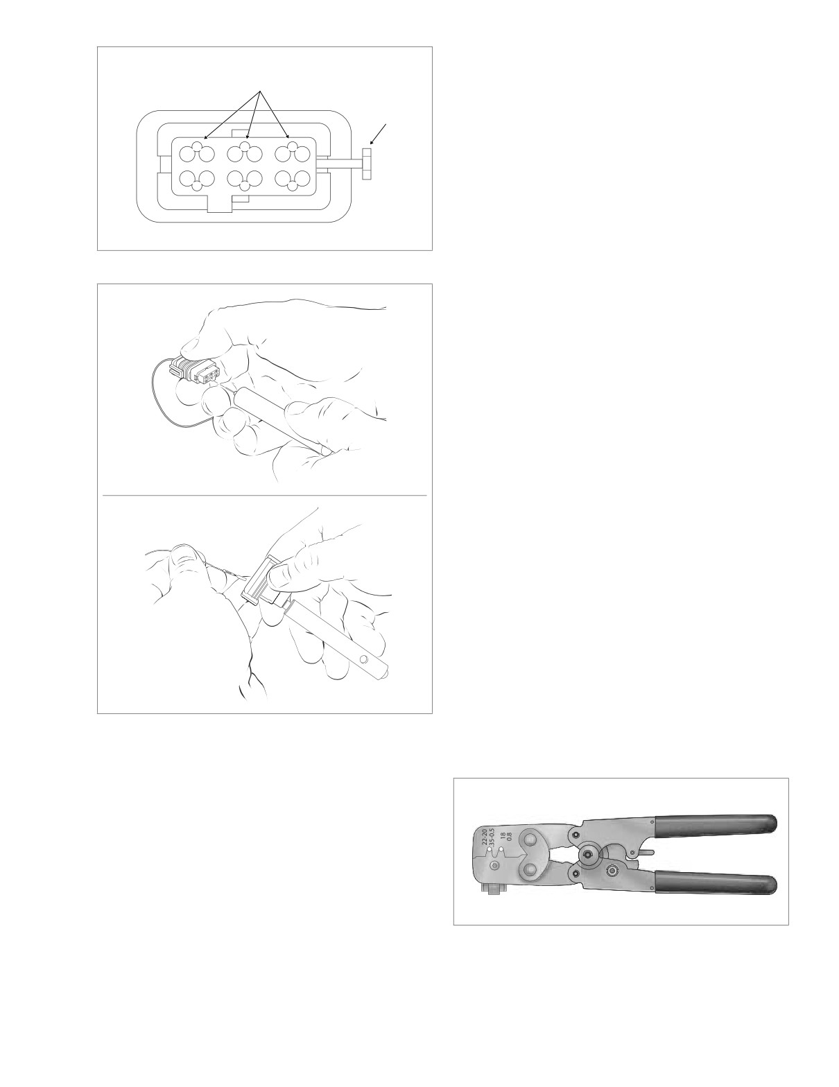
a. Locate small hole between terminals on mating end
of connector. See Figure 8-44.
f2246x8x
b. Push the adjacent terminals all the way into the con-
C
nector housing and then insert tool into hole until it
bottoms. See upper frame of Figure 8-45.
Figure 8-42. Remove Socket Terminals
Assembly
1. Install socket terminals as follows:
a. Carefully bend tang outward away from the terminal
body. See C of Figure 8-42.
b. Feed socket into wire end of socket housing until it
“clicks” in place. Verify that socket will not back out
of chamber. A slight tug on the cable will confirm
that it is locked.
Figure 8-43. Packard Micro 64 Terminal Remover
c. Push rubber seal into wire end of socket housing.
(Part No. HD-45928).
8-32
2004 Touring: Wiring
HOME
NOTE
Small
f2202x8x
For wire location purposes, the corners of the socket housing
Hole
are stamped with the numbers 1, 6, 7 and 12, representing
1
6
Secondary
terminals 1-6 on one side, and 7-12 on the other. See Figure
Lockpin
8-44.
2.
Bottom the terminal in the chamber and then gently tug
1
2
3
4
5
6
on the wire to verify that it is locked in place.
7
8
9
10
11
12
NOTE
Once the terminal is removed it may not lock in place when
first reinstalled. Until the lock engages, move the terminal
7
12
back and forth slightly while wiggling the lead.
Figure 8-44. Mating End of Connector
3. Since the terminal remover tool releases two terminals
simultaneously, repeat step 2 on the adjacent terminal
even if it was not pulled from the connector housing.
4. With the center ear on the head of the secondary lockpin
facing the mating end of the connector, push lockpin in
until head is flush with the connector housing.
5. Push the pin and socket halves of the connector
together until the latches “click.”
Crimping Instructions
1.
Strip lead removing 1/8 inch (3.0 mm) of insulation.
f2196x8x
2.
Obtain the Packard Micro 64 Terminal Crimper (HD-
45929). See Figure 8-46.
3.
Squeeze the handles to cycle the tool to the fully open
position.
4.
Obtain new contact (socket terminal). Verify that contact
and crimp tails are not bent or deformed.
5.
Raise locking bar and barrel holder by pushing up on
bottom tab with index finger. See Figure 8-47.
6.
With the crimp tails facing upward, insert contact
through locking bar into front hole in barrel holder (20-22
gauge wire).
7.
Release locking bar to lock position of contact. When
f2197x8x
correctly positioned, the locking bar fits snugly in the
space at the front of the core crimp tails and the closed
Figure 8-45. Insert Tool and Remove Terminal
side of the terminal rests on the outer nest of the crimp
tool. See Figure 8-48.
c. Leaving the tool installed, gently tug on wires to pull
either one or both terminals from wire end of con-
nector. See lower frame of Figure 8-45. Remove
tool.
5.
If necessary, crimp new terminals on wires. See Crimp-
ing Instructions on this page.
Assembly
1. Insert terminal into its respective numbered chamber on
wire end of connector. No special orientation of the ter-
Figure 8-46. Packard Micro 64 Terminal Crimper
minal is necessary.
(Part No. HD-45929)
2004 Touring: Wiring
8-33
HOME
11. Inspect the quality of the core and insulation crimps. Dis-
tortion should be minimal.
PACKARD 100W
General
Use the following instructions to service the ECM connector.
f2198x8x
Figure 8-47. Raise Locking Bar and Barrel Holder
Disassembly
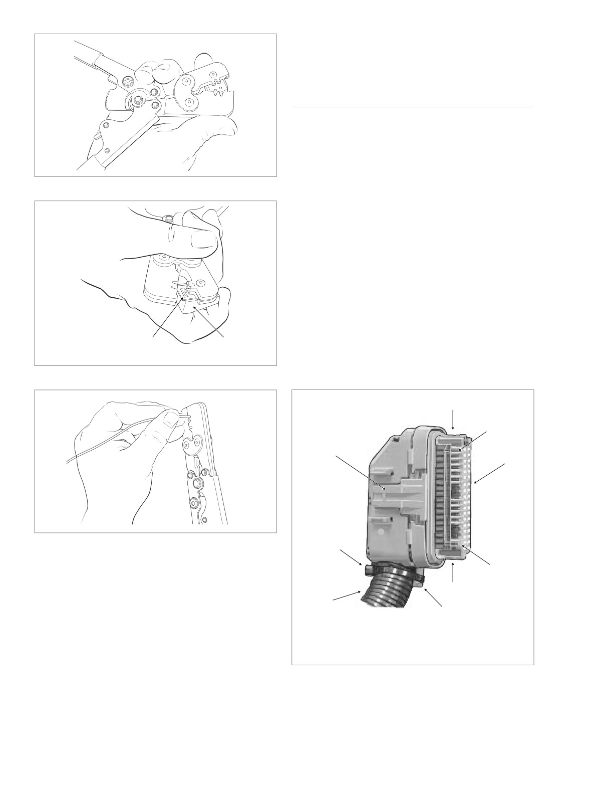
1.
Gently depress latch on each side of the clear plastic
f2199x8x
secondary lock and remove. For best results, release
one side at a time, See Figure 8-50.
2.
Carefully cut cable strap to free strain relief collar from
conduit.
3.
Using a thin blade, gently pry at seam at back of socket
housing to release three plastic pins from slots in hous-
ing. Separate and spread halves of socket housing. See
Figure 8-51.
4.
Push on selected wire to free terminal from chamber.
See Figure 8-52.
Locking
Barrel
5.
If necessary, crimp new terminals on wires. See Crimp-
Bar
Holder
ing Instructions on the next page.
Figure 8-48. Position Contact in Crimper
1
f2062x8x
2
7
3
f2201x8x
Figure 8-49. Crimp Terminal Onto Wire
6
2
8.
Insert wires between crimp tails until ends make contact
with locking bar. Verify that wire is positioned so that
1
wide pair of crimp tails squeeze bare wire strands, while
5
the narrow pair folds over the insulation material.
4
1. Latch
9.
Squeeze handle of crimp tool until tightly closed. Tool
2. Rib
5.
Conduit
automatically opens when the crimping sequence is
3. Secondary Lock
6.
Cable Strap
complete. See Figure 8-49.
4. Strain Relief Collar
7.
External Latch
10. Raise locking bar and barrel holder to remove contact.
Figure 8-50. Remove Secondary Lock
8-34
2004 Touring: Wiring
HOME
Crimping Instructions
1.
Strip wire lead removing 5/32 inch (4.0 mm) of insula-
tion.
2.
Compress handles until ratchet automatically opens.
NOTE
Pins
Always perform core crimp before insulation/seal crimp.
3.
See Figure 8-53. Determine the correct dye or nest for
the core crimp.
4.
Position the core crimp on the appropriate nest. Be sure
the core crimp tails are facing the forming jaws.
5.
Gently apply pressure to handles of tool until crimpers
just secure the core crimp tails.
f2063x8x
6.
Insert stripped wire between crimp tails. Verify that wire
is positioned so that short pair of crimp tails squeeze
Figure 8-51. Separate Halves of Socket Housing
bare wire strands, while long pair is positioned over the
insulation or seal material.
7.
Squeeze handle of crimp tool until tightly closed. Tool
automatically opens when the crimping sequence is
complete.
8.
See Figure 8-53. Determine the correct dye or nest for
the insulation/seal crimp.
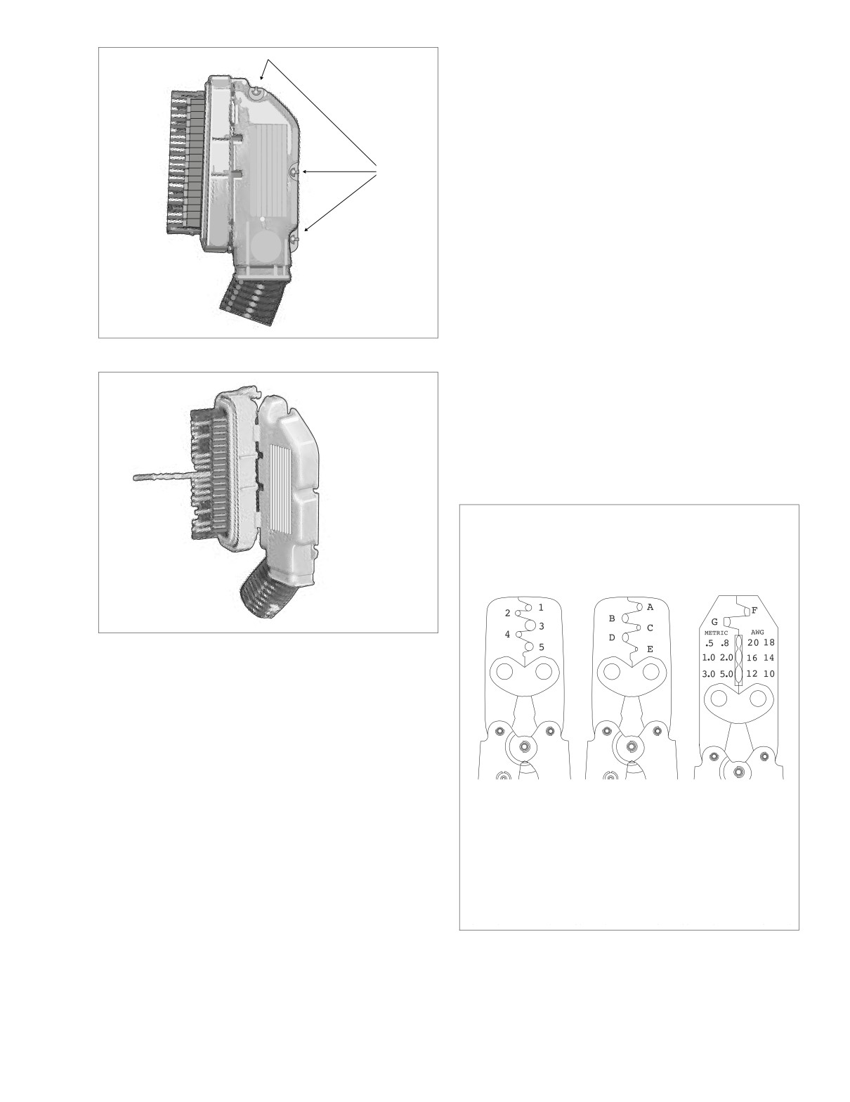
Packard Terminal Crimp Dyes (Nests)
Packard 270
Packard 271
Packard 115
(HD-38125-6)
(HD-38125-7)
(HD-38125-8)
f2064x8x
Figure 8-52. Push Wire to Extract Terminal
Assembly
1. From inside socket housing, gently pull on wire to draw
terminal into chamber. See Figure 8-52.
2. Exercising caution to avoid pinching wires, press halves
Sealed
Non-Sealed
Non-Sealed
of socket housing together until three plastic pins fully
Terminals
Terminals
Terminals
engage slots in housing. See Figure 8-51.
1-5
A-E
F-G
3. Install new cable strap in groove of strain relief collar
capturing cable conduit. See Figure 8-50.
Butt Splices*
4. With the two ribs on the secondary lock on the same
*See Appendix 8.6 SEALED BUTT SPLICE CONNECTORS.
side as the external latch, install over terminals until
latches lock in place.
Figure 8-53.
Packard Terminal
Crimp Tools
2004 Touring: Wiring
8-35
HOME
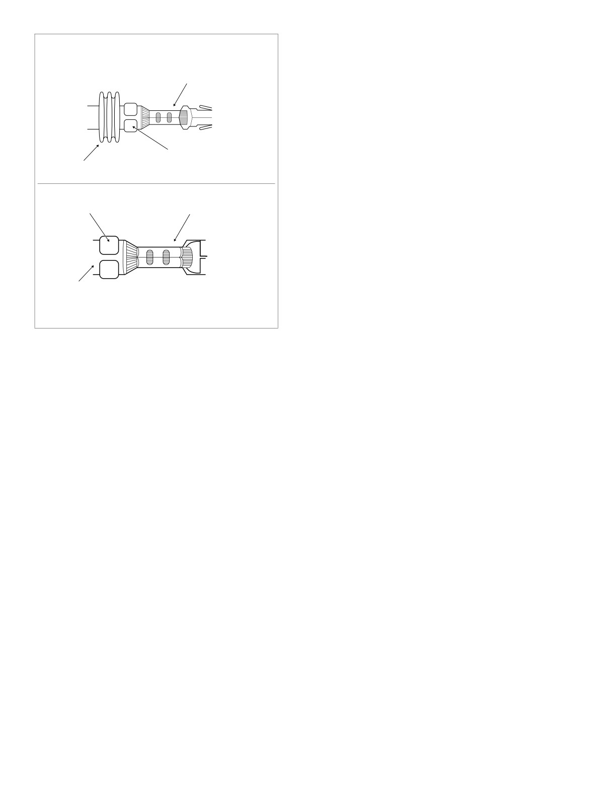
9.
Position the insulation/seal crimp on the appropriate
nest. Be sure the insulation/seal crimp tails are facing
SEALED TERMINAL
the forming jaws.
Core Crimp
10. Squeeze handle of crimp tool until tightly closed. Tool
automatically opens when the crimping sequence is
complete.
11. Inspect the quality of the core and insulation/seal
crimps. Distortion should be minimal. See Figure 8-54.
Seal Crimp
Seal
f1006a8x
f1005a8x
Insulation
Crimp
Core Crimp
Insulation
NON-SEALED TERMINAL
Figure 8-54. Inspect Core and Insulation/Seal Crimps
8-36
2004 Touring: Wiring
HOME
AUTOFUSE ELECTRICAL CONNECTOR
8.5
GENERAL
8821
Use these instructions to service the following connector:
● HDI Ignition Light/Key Switch Jumper Harness [33D]
DISASSEMBLY
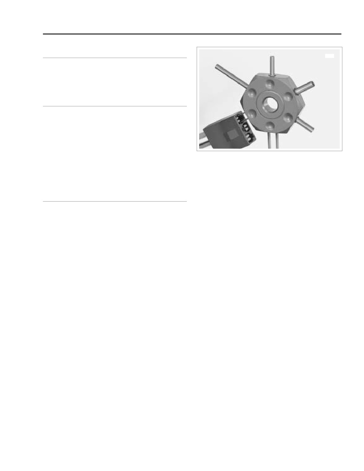
1. Obtain terminal pick
(Snap-on® GA500A) like that
shown Figure 8-55.
2. Insert smallest pair of pins into chamber on mating end
of socket housing to depress tangs on each side of ter-
minal simultaneously.
3. Gently pull on wire to remove terminal from wire end of
Figure 8-55. Depress Tangs and Remove Terminal
socket housing.
4. If necessary, crimp new terminals on wires.
ASSEMBLY
1. Using a thin flat blade, like that on an X-Acto knife, care-
fully bend tang on each side of terminal outward away
from terminal body.
2. With the open side of the terminal facing rib on wire end
of socket housing, insert terminal into chamber until it
locks in place.
2004 Touring: Wiring
8-37
HOME
SEALED BUTT SPLICE CONNECTORS
8.6
8. Repeat steps 5, 6 and 7 on the other side of the butt
PROCEDURE
splice connector.
Butt splicing may be a necessary procedure for the replace-
NOTE
ment of some components. Proceed as follows:
If adjacent wires are being spliced, stagger the splices so
1.
Strip 3/8 inch (9.5 mm) of insulation off the ends of the
that the butt splice connectors are spaced at different posi-
wires.
tions along the length of the wires.
2.
Compress the handles of the Packard Crimp Tool (HD-
38125-8) until the ratchet automatically opens.
9.
Using the UltraTorch UT-100 (HD-39969), Robinair Heat
3.
Since the size of the connectors vary with the gauge of
Gun
(HD-25070) with heatshrink attachment
(HD-
the wire, reference the following table to ensure properly
41183) or other suitable radiant heating device, heat the
sealed splices are used.
crimped splice to encapsulate the butt splice connection.
Apply heat from the center of the crimp out to each end
until the meltable sealant exudes out both ends of the
Gauge
Connector
Part
connector. See Figure 8-57.
Wire
Color
Number
18-20
Red
P/N 70585-93
14-16
Blue
P/N 70586-93
Red
10-12
Yellow
P/N 70587-93
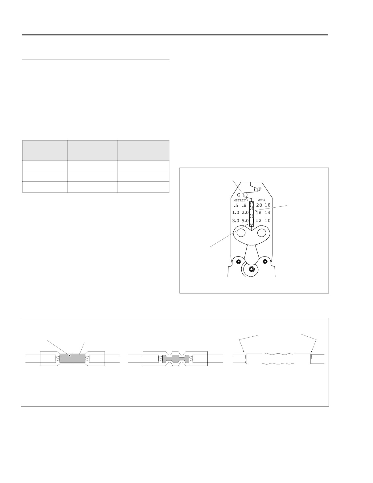
4.
Determine the correct dye or nest for the crimping oper-
Blue
ation. Match the color or gauge wire marked on the butt
splice connector with the corresponding crimp cavity on
the crimp tool. See Figure 8-56.
5.
Gently apply pressure to the handles until the crimper
lightly secures one side of the metal insert inside the butt
splice connector. The connector must be crimped in two
Yellow
stages, one side and then the other.
6.
See Figure 8-57. Feed the wire into the butt splice con-
nector until the stripped end contacts the wire stop
inside the metal insert.
7.
Squeeze the handles of the crimp tool until tightly
closed. The tool automatically opens when the crimping
se-quence is complete.
Figure 8-56. Packard Crimp Tool (HD-38125-8)
Wire
Metal
Melted Sealant
Stop
Insert
Insert stripped wire
Crimp wire ends
Apply heat and allow
ends into connector
in connector
connector to cool
f1203b8x
Figure 8-57. Installing Sealed Butt Splice Connectors
8-38
2004 Touring: Wiring
HOME
NOTE
1WARNING
It is acceptable for the splice to rest against the heat shrink
tool attachment.
Use extreme caution when operating the UltraTorch UT-
100 or any other radiant heating device. Read the manu-
10. Heat the center of the splice until the crimp indentations
facturers instructions carefully before use. Always keep
disappear and the tubing assumes a smooth cylindrical
hands away from tool tip area and heat shrink attach-
appearance.
ment. Avoid directing the heat toward any fuel system
component. Extreme heat can cause fuel ignition/explo-
sion. Avoid directing heat toward any electrical system
component other than the connectors on which heat
shrink work is being performed. Be sure to turn the “ON/
OFF” switch to the “OFF” position after use. Inadequate
safety precautions could result in death or serious
injury.
2004 Touring: Wiring
8-39
HOME
AMP ELECTRICAL CONNECTORS
8.7
4. Holding the socket housing while keeping the tool firmly
1-PLACE CONNECTOR
bottomed, depress the plunger. The terminal pops out
the wire end of the connector.
The 1-place Amp MATE-N-LOK connector can be found on
some Touring models.
NOTE
If the terminal is not released from the socket housing, then
the terminal was not pushed forward far enough before
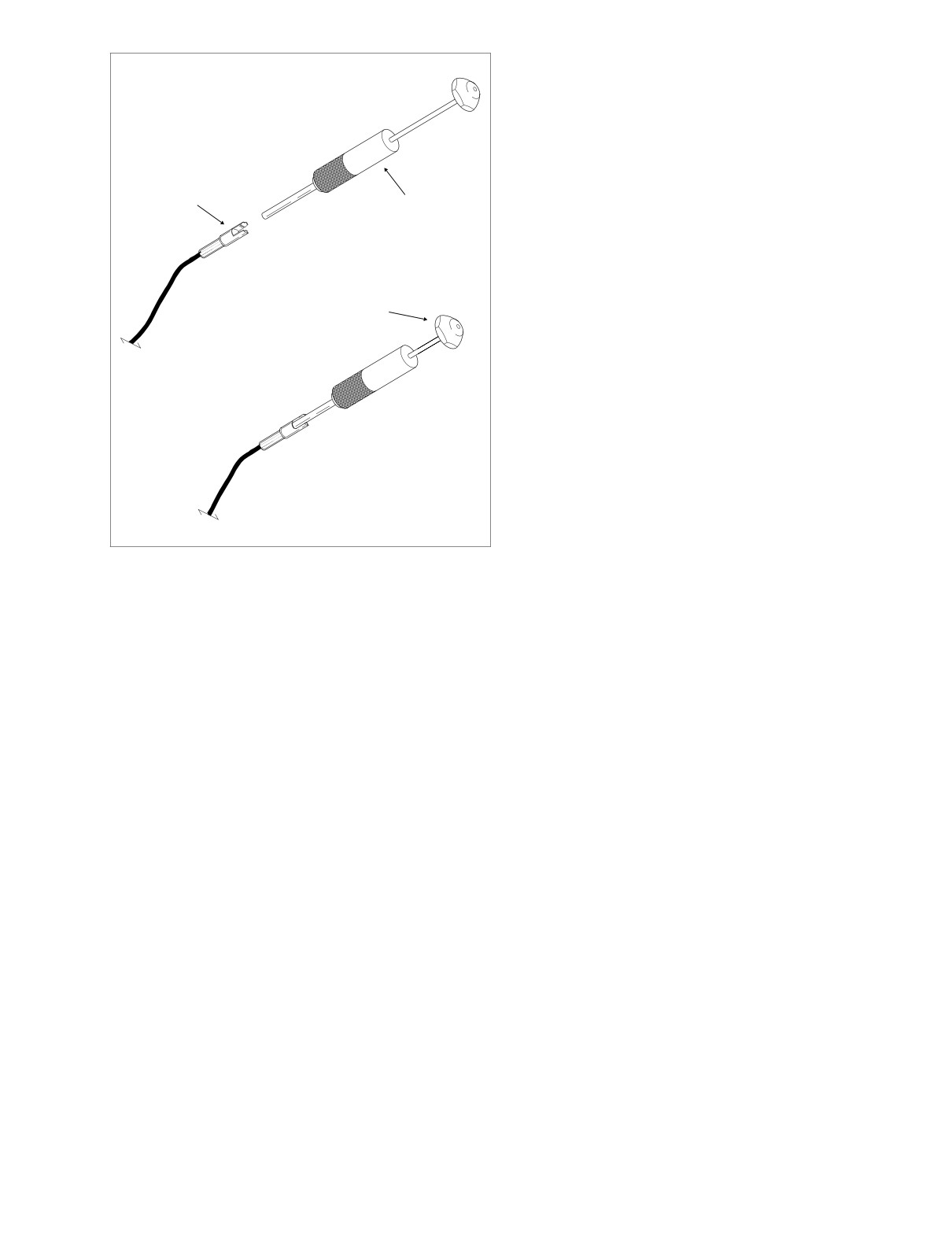
Socket Terminal
placement of the tool or the tool was not bottomed in the con-
nector housing.
Removal
1.
Bend back the ears on the pin housing slightly and sepa-
rate the pin and socket halves of the connector.
Installation
2.
Grasp the lead on the wire end of the socket housing
1.
Note the lip at the middle of the socket housing. One
and push the terminal forward toward the mating end of
side of the lip is flat while the other side is tapered. Insert
the connector until it stops. This will disengage the lock-
the wire terminal into the socket housing on the flat lip
ing tang from the groove in the connector.
side.
3.
Fit the barrel of the Amp Socket Terminal Remover (HD-
2.
Push the lead into the socket housing until it stops. A
39621-27) over the socket, and while rotating the tool
click is heard when the terminal is properly seated.
slightly, push until it bottoms in the housing. Allow the
plunger to “back out” of the handle. See Figure 8-58.
3.
Gently tug on the lead to verify that the terminal is locked
in place.
4.
Push the pin and socket halves of the connector
together until the latches “click.”
A
Install Socket Terminal Remover
Pin Terminal
Removal
Socket
1.
Bend back the ears on the pin housing slightly and sepa-
Housing
Amp Socket
rate the pin and socket halves of the connector.
Terminal Remover
(HD-39621-27)
2.
Grasp the lead on the wire end of the pin housing and
push the terminal forward toward the mating end of the
connector until it stops. This will disengage the locking
Lip
tang from the groove in the connector.
Plunger
3.
Fit the barrel of the Amp Pin Terminal Remover (HD-
39621-28) over the pin, and while rotating the tool
slightly, push until it bottoms in the housing. Allow the
plunger to “back out” of the handle. See Figure 8-59.
4.
Holding the pin housing while keeping the tool firmly bot-
tomed, depress the plunger. The terminal pops out the
B
Depress Plunger
wire end of the connector.
NOTE
If the terminal is not released from the pin housing, then the
terminal was not pushed forward far enough before place-
ment of the tool or the tool was not bottomed in the connector
f1364x8x
housing.
Figure 8-58. Remove Terminal from Amp Socket Housing
8-40
2004 Touring: Wiring
HOME
Installation
A
Install Pin Terminal Remover
1.
Push the lead into the pin housing until it stops. A click is
heard when the terminal is properly seated.
2.
Gently tug on the lead to verify that the terminal is locked
in place.
Pin
3.
Push the pin and socket halves of the connector
Housing
together until the latches “click.”
Amp Pin
Terminal Remover
(HD-39621-28)
Plunger
B Depress Plunger
f1366x8x
Figure 8-59. Remove Terminal from Amp Pin Housing
2004 Touring: Wiring
8-41
HOME
NOTES
8-42
2004 Touring: Wiring
HOME
WIRING DIAGRAMS
8.8
SUBJECT
PAGE NO.
FLHT, FLHTC, FLHTCU
Main Harness
8-45
Interconnect Harness
8-46
Ignition Harness (Carbureted)
8-47
Electronic Fuel Injection (EFI) Harness
8-47
Ignition Switch
8-48
Tail Lamp, Passing Lamps, Fender Tip Lamps, Directional Lamps
and Tour-Pak Lights
8-48
Starting and Charging
8-49
Handlebar Controls and Indicator Lamps
8-50
Fairing Cap Switches
8-50
Radio, CB/Intercom and Rear Speakers
8-51
FLTR
Main Harness
8-45
Interconnect Harness
8-46
Ignition Harness (Carbureted)
8-47
Electronic Fuel Injection (EFI) Harness
8-47
Ignition Switch
8-48
Tail Lamp and Directional Lamps
8-48
Starting and Charging
8-49
Handlebar Controls and Indicator Lamps
8-50
Instrument Nacelle Switches
8-50
Radio
8-51
FLHR, FLHRC, FLHRS
Main Harness
8-52
Ignition Harness (Carbureted)
8-53
Electronic Fuel Injection (EFI) Harness
8-53
Starting and Charging
8-54
Handlebar Controls, Speedometer, Indicator Lamps, Tail Lamp, Passing Lamps,
Directional Lamps, Fender Tip Lamps and Spot/Accessory Switches
8-55
TLE Sidecar, TLE Ultra Sidecar
Chassis
8-56
Audio Harness
8-56
NOTE
Harness Part No.’s may be included on some wiring diagrams. Use these numbers for reference only.
ALWAYS REFER TO THE PARTS CATALOG WHEN ORDERING WIRING HARNESSES.
2004 Touring: Wiring
8-43
HOME
NOTES
8-44
2004 Touring: Wiring
HOME
CARBURETED ONLY
TSM/TSSM
EFI
40A
BATTERY
1
BN/GY
IGNITION
2
GY
FUEL LEVEL
OPTIONAL
MAXI-FUSE
TO
VSS/SERIAL DATA LINK
3
LGN/V
SENDER
SECURITY
IGNITION
KEYSWITCH IGN RELAY
SECURITY INDICATOR
4
BN/V
FUEL
SIREN
SWITCH
LEFT TURN FEED
5
V
PUMP
[33B]
RIGHT TURN FEED
6
BN
VOLTAGE
B+
RIGHT TURN SW INPUT
7
W/BN
REGULATOR
CONNECTOR
A B C D
[126A]
LEFT TURN SW INPUT
8
W/V
FUEL PUMP
[141A]
START RELAY CONTROL
9
TN/GN
ASSEMBLY
[142A]
[5B]
A B
[33A]
IGNITION ENABLE
10
IN TANK
1
2
3
85863087A
ALARM SIGNAL
11
LGN/BN
GROUND
12
BK
AT TOP OF TANK
1
2
3
A B C
[77A]
[160B]
[126B]
[141B]
MAIN POWER
[30A]
[30B]
TURN SIGNAL/
[142B]
AT STARTER
TURN SIGNAL SECURITY
(GY)
70369-02
MODULE
FUEL TANK
[13B]
HARNESS
1
2
3
12
BK
[141A]
11
LGN/V
1
2
3
10
O/GY
1 2 3
TO
9
R
[13A]
IGNITION/EFI
8
BK
7
R
HARNESS
6
GY
[8A]
5
W/GN
(GY)
4
3
BE/O
[64B]
2
W/BK
1
BN/GY
O/V
4E
3
RH GND
R/Y
3F
5
[8B]
BK/GN
STUD
BK
BRAKE
R/BE
3E
2
RELAY
- FRAME GROUND -
BK
4F
1
12
11
GN/R
BK
LH GND
BK
W/V
10
STUD
1B
INSTRUMENTS - 15A
1A
W/BN
TO
9
O
R/BK
O/BE
INTERCONNECT
8
BN
1D
LIGHTS - 15A
1C
HARNESS
7
V
BE
6
W/BK
1H
HEADLAMP - 15A
1G
[1A]
5
O/W
BE
R/BK
(BK)
4
O/R
1F
IGNITION - 15A
1E
START RELAY
3
GY
GY
2
O/V
4D
P&A IGN - 2A MAX
4C
1
O
R/BK
[123A]
2B
CRUISE/BRAKE - 15A
2A
[1B]
O/V
R/GY
85863087A
2D
ACCESSORIES - 15A
2C
O/W
12
BK
[123B]
2F
P&A - 15A
2E
11
W/GN
O/R
10
TN
TO
3B
RADIO MEM - 15A
3A
9
GN/Y
INTERCONNECT
R/O
R
8
BN/GN
3D
BATTERY - 15A
3C
HARNESS
7
O
BN/GY
[2A]
6
Y/BK
5
Y/W
RADIO PWR - 10A
(GY)
4B
4A
4
BN/GY
O/BE
O/GN
3
BE
2
BK/R
1
R/BE
[2B]
[128B]
TO
D
BK
INTERCONNECT
C
BK/GN
START
HARNESS
B
BE
[15A]
A
R/O
SOLENOID
[15B]
CRANK POSITION
SENSOR
BK
4
O
3
ACCESSORY
R/Y
2
CONNECTOR
O/R
1
(BK)
BK
2
2
[12B]
[4A]
BK
R
1
1
32 1
(BK - LOCATED UNDER SEAT)
[79A]
[79B]
NEUTRAL
SWITCH
TOUR-PAK
[12A]
BN/GN
GN/Y
[131]
[17B]
THROTTLE
ROLL-OFF
HORN
[75C]
[139B]
SWITCH
D C B A
[7A]
REAR
[17A]
OIL
[75A]
[156A]
1 2
3 4 5 6 7 8
PRESSURE
[75D]
STOPLIGHT
SWITCH
TO REAR
SENDER
6 5
4 3
2 1
O/V
[121]
LIGHTING
[139A]
Y/V
[122 ]
TO INTERCONNECT
[7B]
[75B]
[156B]
f2227z8x
(GY)
CRUISE CONTROL MODULE
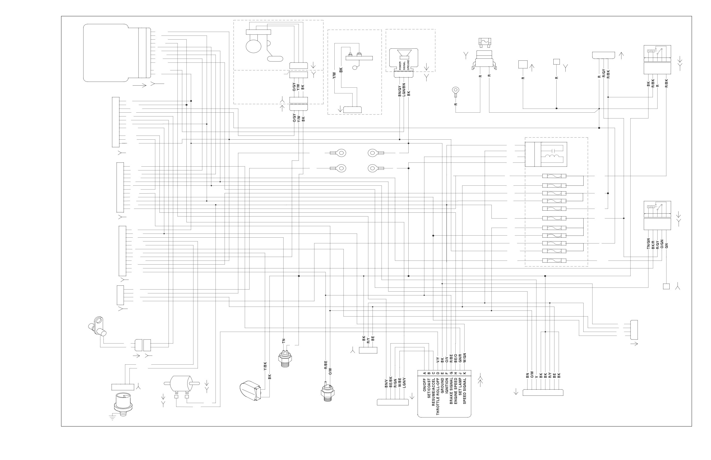
2004 FLHT, FLHTC, FLHTCU and FLTR, DOMESTIC and INTERNATIONAL Models,
Main Harness
8-45
HOME
[21B]
[105B]
NOTE: OIL PRESSURE GAUGE AND AIR TEMP GAUGE
FRONT FENDER
TO DASH PANEL
TO INDICATOR
TIP LAMP
NOT INCLUDED ON FLHT AND FLHTP
2
BK
LAMPS
SWITCHES
[32B]
1
BE
OIL
(BK)
1
2
3
4
5
6
7
8
9
10
1211109
8
7
6
5
4
3
2
1
AIR
FUEL
VOLTMETER
PRESSURE
[32A]
TEMPERATURE
[21A]
[105A]
(BK)
(BK)
[116A]
[116B]
[110A]
[110B]
[112A]
[112B]
[114A]
[114B]
PASSING
2
GY/BK
1
2
1
2
1
2
1
2
[115A]
LAMPS
1
GY/BK
S
[111A]
[113A]
+
S
[117A]
+
+
S
+
S
[73B]
1
3
1
3
1
3
1
3
[73A]
2
2
2
2
(WE)
LO_BEAM
[115B]
[111B]
[113B]
HEADLAMP
[117B]
[38B]
Y
HI_BEAM
W
GND
HDI ONLY
BK
[29B]
BK
(BK)
[107B]
O/W
BE/V
1
2
TEMP SIGNAL
[22A]
GROUND
BK
3
1
O/W
2
AIR
R/BE
3
GY
TEMPERATURE
4
W/BK
TO
SENSOR
5
W/BN
RIGHT HAND
6
[107A]
BK/R
CONTROLS
7
BN/W
[22B]
8
GY/W
(BK)
9
PK/W
10
V/BK
11
W/BE
12
BE/BK
GN/R
12
W/V
11
GROUND
W/BN
10
[GND3]
TO
TO UPPER
O/BE
9
TRIPLE
BK/GN
BN
8
MAIN
BK/GN
V
7
HARNESS
CLAMP
GROUND EXTENDED ON
W/BK
6
(BLACK)
FLTR. P/N 70420-98
O/W
5
[1B]
O/R
4
12
O/BK
GY
3
11
GY/GN
O/V
2
10
GN/BE
O
1
TO
9
PK/W
8
BN/BK
[1A]
LEFT HAND
7
V/BK
CONTROLS
6
Y/BK
[24B]
5
W/V
BK
12
4
W
W/GN
11
(GY)
3
BE
TN
10
TO
2
Y
GN/Y
9
1
O/W
BN/GN
8
MAIN
O
7
HARNESS
[24A]
Y/BK
6
(GRAY)
Y/W
5
[2B]
[27B]
BN/GY
4
BE
3
1
LGN/BK
BK/R
2
2
BE/Y
R/BE
1
3
PK/W
4
GY/W
[2A]
5
V/BK
6
BN/W
TO
7
BK
D
O/BK
MAIN
8
BK/GN
C
BN/BK
HARNESS
9
W/GN
BE
B
10
R/O
A
[15B]
TO
11
BK/GN
(BK)
RADIO
12
O/BE
[15A]
[27A]
13
BN/O
[39B]
(BK)
14
R/O
(BK)
[108B]
15
V/GY
1
2
3
4
5
6
7
8
9 1011 12
(GY)
16
W/O
1
23
4
56
7
8
910 1112
17
LGN/W
18
GY/R
O/W
19
BK/GN
CIGAR
20
R/O
BK
LIGHTER
21
V/O
[132B]
22
GY/GN
23
GN/BE
RIGHT
[34B]
[6B]
[156B]
FRONT
[31R]
[31L]
SPEAKER
[31A]
RPM x 100
LGN/BK
(EXCEPT FLHT)
GY/R
A B C
1
2
3
4
5
6
3
2
1
3
2
1
(BK)
6
5 4
3
2
1
TO MAIN
RH FRONT
LH FRONT
TO AUDIO
TURN SIGNAL
TURN SIGNAL
TURN SIGNALS
ODOMETER
[35B]
HARNESS
RESET
LEFT
HARNESS
FLHT/I, FLHTC/I
[156A]
FLTRI ONLY
SWITCH
[6A]
FLHTCUI ONLY
FRONT
LGN/W
(GY)
SEPARATE CONNECTORS
[154A]
(BK)
FOR FRONT
SINGLE CONNECTOR
SPEAKER
W/O
FOR FRONT
TURN SIGNALS
f2227y8x
(EXCEPT FLHT)
TURN SIGNALS
SPEEDOMETER
TACHOMETER
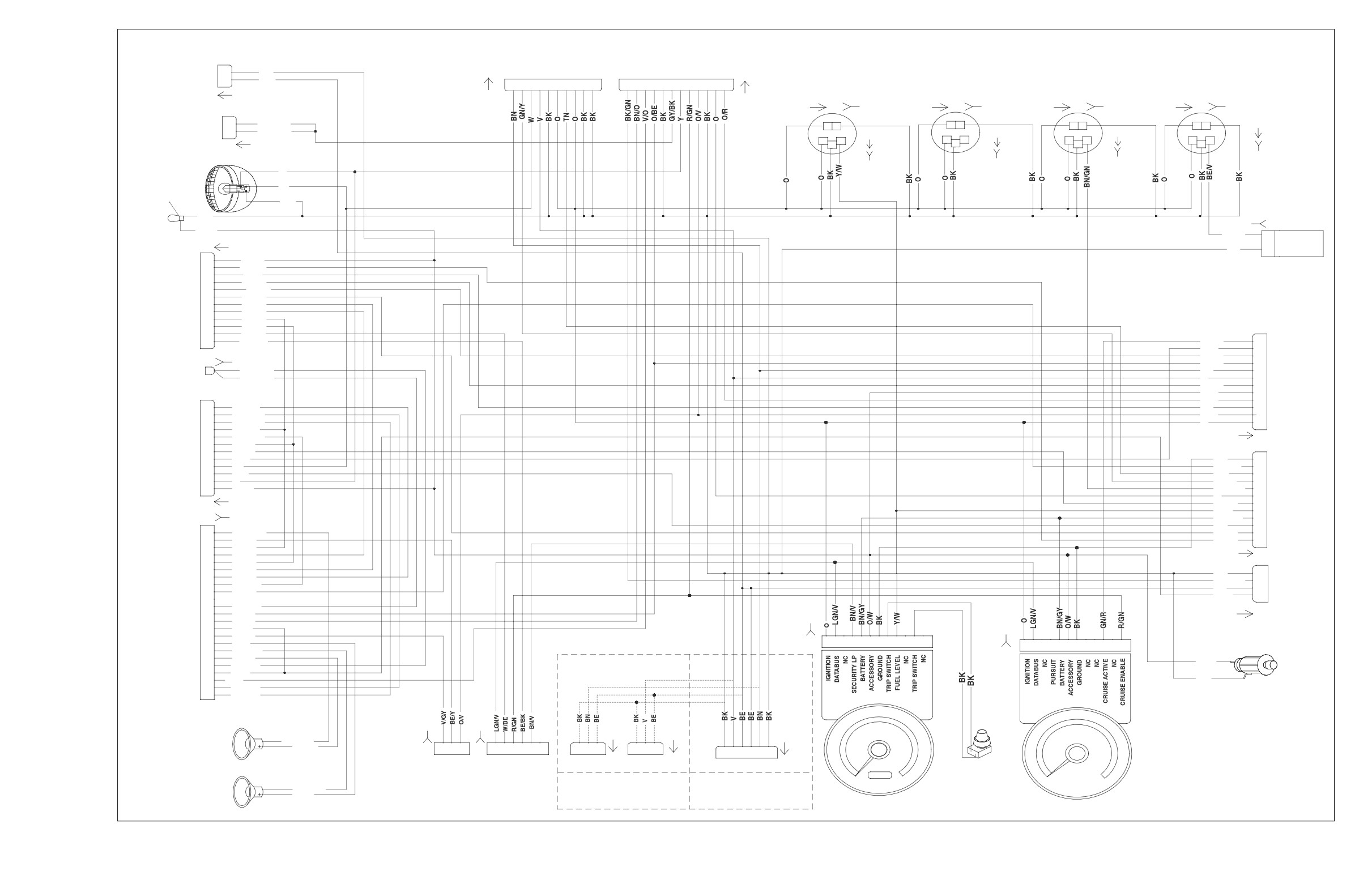
2004 FLHT, FLHTC, FLHTCU and FLTR, DOMESTIC and INTERNATIONAL Models,
Interconnect Harness
8-46
HOME
MAP
DATA
IGNITION
SENSOR
C B A
LINK
COIL
+5V DC
CARBURETED
(GY)
1234
CB A
R/W
A
A
R
IGNITION
W/GN
B
B
W
COIL
VEHICLES
[91A]
[83B]
[80A]
[83A]
BK
C
C
BK
(CARB)
OUTPUT
[65B]
SENSOR
GROUND
C B A
(BK)
[65A]
IGNITION CONTROL MODULE
VEHICLE
[80B]
SPEED SENSOR
(BLK)
[BLK]
[10A]
[10B]
BK
12
RUN/STOP SIGNAL
1
ABCD
[83A]
1
W/BK
LGN/V
11
BATTERY
2
10
2
BN/GY
FRONT SPARK
IGNITION
+5V SENSOR PWR
3
R/W
9
FROM
REAR SPARK PLUG
COIL
3
PLUG
SENSOR GROUND
4
BK/W
BK
8
4
MAIN
(EFI)
MODULE GROUND
5
BK
R
7
5
HARNESS
COIL FRONT
6
BE/O
GY
6
6
[8B]
COIL REAR
7
Y/BE
W/GN
5
7
CRANK SENSOR (+)
8
8
R
4
9
BK
BE/O
3
CRANK SENSOR (-)
9
10
W/GN
W/BK
2
VEHICLE SPD SIG
10
11
V/W
BN/GY
1
MAP SIGNAL
11
+5V DC
12
12
LGN/V
DATALINK
[8A]
R/W
A
A
R
W/GN
B
B
W
(GY)
BK
C
C
BK
OUTPUT
[65B]
SENSOR
(BK)
[65A]
GROUND
CARBURETED OVERLAY: 32435-04
VEHICLE
EFI OVERLAY: 70233-04
SPEED SENSOR
REAR
FRONT
INTAKE
ENGINE
INJECTOR
INJECTOR
AIR
IDLE AIR
TEMP.
TEMP.
CONTROL ACTUATOR
SENSOR
SENSOR
THROTTLE
MAP
BK
12
POSITION
LGN/V
11
FUEL INJECTED
SENSOR
SENSOR
O/GY
10
R
9
FROM
VEHICLES
DATA
IGNITION
BK
8
R
MAIN
LINK
COIL
7
(GY)
GY
6
HARNESS
1
2
3
4
AB
AB
ABCD
W/GN
5
[8B]
[91A]
4
ELECTRONIC
DCB A
PK
3
(GY)
[83B]
AB
AB
CB A
CBA
[87B]
CONTROL
[90B]
[89B]
W/BK
2
MODULE
[85B]
1
[84B]
[88B]
[80B]
[78A]
[78B]
[8A]
ALDL & FLASH PIN
LGN/R
CHECK ENG LP
TACH OUTPUT
PK
SYSTEM RELAY
GN/O
SERIAL DATA LINK
LGN/V
ENGINE TEMPERATURE
PK/Y
INTAKE AIR TEMPERATURE
LGN/Y
OXYGEN SENSOR A
ANALOG INPUT
POWER GROUND
BK
COIL REAR
Y/BE
[119B]
CRANK POS. SENSOR (-)
BK+
SWITCH POWER
W/BK
FUEL PUMP 15A
5V SENSOR POWER
R/W
G
H
DIGITAL GROUND
O/GY
Y/GN
FREQUENCY INPUT
IDLE AIR CNTL MOTOR
BK/O
ECM POWER 15A
IDLE AIR CNTL MOTOR
BK/PK
A
B
INJECTOR REAR
GN/GY
BE/GY
R
OUTPUT (unused)
INJECTOR FRONT
W/Y
SYSTEM RELAY
(BK)
OUTPUT (UNUSED)
OXYGEN SENSOR B
Y/GN
K
5
THROTTLE POS SNSR INPUT
GY/V
T
4
MAP SENSOR INPUT
V/W
BE/GY
E
3
5V SENSOR GROUND
BK/W
GN/O
S
2
ION SENSE
GY/BE
W/BK
U
1
POWER GROUND
BK
COIL FRONT
BE/O
CRANK POS. SNSR (+)
R
CONSTANT POWER
BE/GY
SWITCH INPUT (unused)
VEHICLE SPEED INPUT
W/GN
DIGITAL POWER
IDLE AIR CNTL MOTOR
BE/GN
IDLE AIR CNTL MOTOR
BN/R
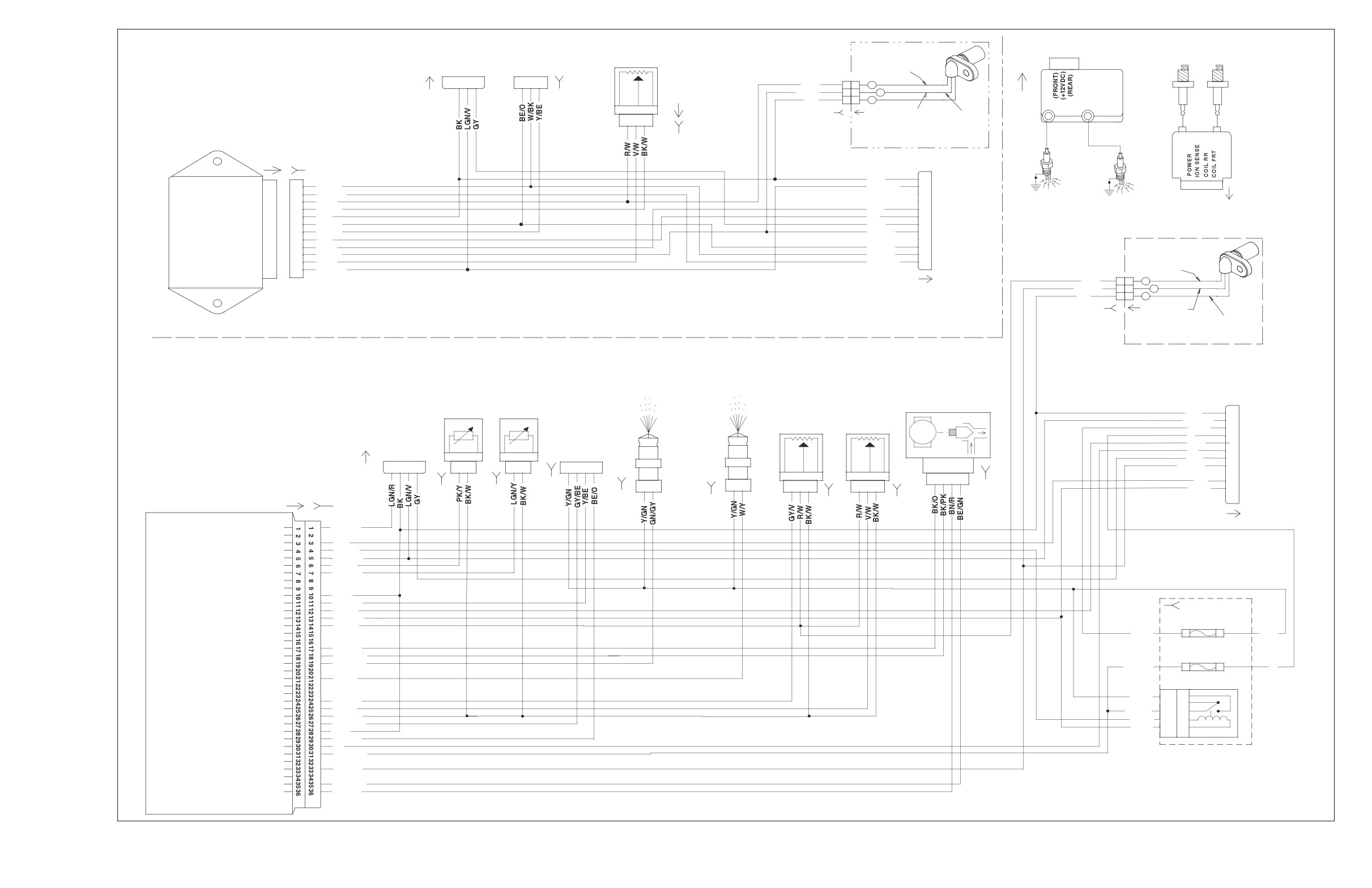
f2227x8x
2004 FLHT, FLHTC, FLHTCU and FLTR, DOMESTIC and INTERNATIONAL Models,
Ignition Harness (Carbureted), Electronic Fuel Injection (EFI) Harness
8-47
HOME
1 2
3 456 78
FROM MAIN
REAR LIGHTING
HARNESS [7A]
[7B]
RIGHT PURSUIT
LAMP (BLUE)
RIGHT REAR
POLICE ONLY
FROM
FROM
DIRECTIONAL
INTERCONNECT
INTERCONNECT
68772-99
LAMP
HARNESS [73A]
HARNESS [32A]
RIGHT
PASSING
2 1
2 1
LAMP
[73B]
[32B]
BK
TAILLAMP
R/Y
O/W
BEW
[94B] BRAKE LIGHT
654 3
2
1
654 3
2
1
FENDER TIP LAMP
[143B]
[143A]
[19b]
[94A]
(DOM ONLY)
[19a]
O/W
1
1
V/BN
1
1
BK
2
2
BK
2
2
RUNNING LIGHT (DOM)
LICENSE
[18a]
[18B]
PLATE LAMP
RUNNING LIGHT (HDI)
(HDI ONLY)
V/BN
1
1
BK
2
2
4
4
1
1
3
3
BK
2
2
2
LEFT
2
FENDER TIP LAMP
3
3
1
BK
PASSING
1
(DOMESTIC ONLY)
LAMP
[93B]
[45B]
[45A]
[93A]
LEFT PURSUIT
LAMP (RED)
LEFT REAR
POLICE ONLY
DIRECTION
LAMP
3
2
1
TOUR-PAK RIGHT SIDE
ULTRA TOUR-PAK
TO MAIN
MARKER LIGHTS
IGNITION SWITCH LEGEND (HDI)
FROM
[12B]
REAR MARKER/
INTERCONNECT
HARNESS
"X" INDICATES CONTINUITY
BK
STOP LIGHTS
BETWEEN LEAD WIRES
HARNESS [31A]
[12A]
SWITCH
IN POSITION INDICATED
POSITION
RED/
RED/
6
5
4
3
2
1
RED
GRAY
BLACK
BK
LOCK
X
[31B]
BE
OFF
X
TAIL
IGN
X
X
X
[12-2A]
BE
BK
ACC
X
X
1 2
R/Y
RIGHT
1 2
BK
DIRECTIONAL
[12-2B]
BE
AND DOM
BN
RUNNING LAMP
STOP
R/GY
1
1
R/GY
[33B - HDI]
R
2
2
R
R/BK
3
3
R/BK
BLUE WIRES (RUNNING) ARE ONLY
BE
IGNITION
AVAILABLE ON DOMESTIC MODELS
A
FROM MAIN
SWITCH,HDI
B
HARNESS [33A]
C
D
DOM TOUR-PAK HARNESS:
NOTE:
LEFT
FLHTC P/N
DOM FLHTC
BK
DIRECTIONAL
BE
70646-00
DOES NOT INCLUDE
[12-3B]
IGNITION SWITCH LEGEND (DOM)
AND DOM
V
FLHTC-U
REAR MARKER/STOP
2
1
"X" INDICATES CONTINUITY
RUNNING LAMP
FLHTCU-I
LIGHTS AND
BETWEEN LEAD WIRES
SWITCH
IN POSITION INDICATED
P/N 70648-00
2
1
ASSOCIATED WIRING
POSITION
[ 33B-DOM]
RED
RED/
RED/
GRAY
BLACK
[12-3A]
LOCK
X
BE
OFF
X
FROM MAIN
A
R
IGN
X
X
X
B
R/GY
ACC
X
X
TOUR-PAK LEFT SIDE
BK
HARNESS [33A]
C
R/BK
MARKER LIGHTS
D
IGNITION
SWITCH,DOM
HDI FLHTC AND FLHTCU MODELS DO NOT HAVE TOUR-PAK LIGHTING
TOUR-PAK NOT INCLUDED ON FLHT OR FLHTP
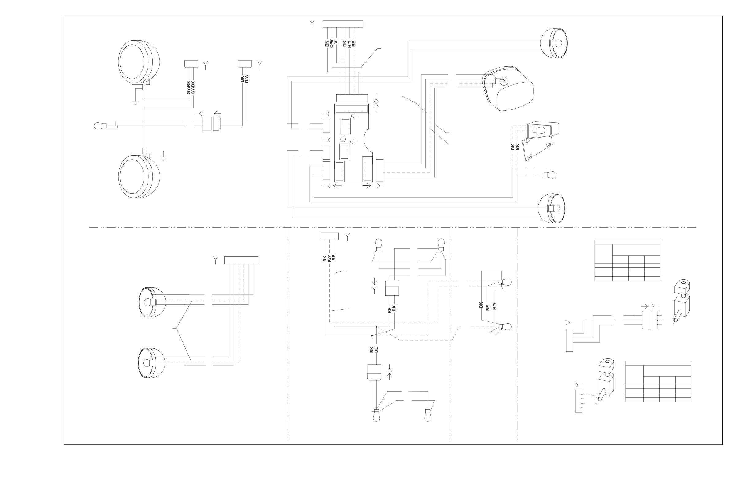
f2227u8x
2004 FLHT, FLHTC, FLHTCU and FLTR, DOMESTIC and INTERNATIONAL Models,
Ignition Switch, Tail Lamp, Passing Lamps, Fender Tip Lamps, Directional Lamps and Tour-Pak Lights
8-48
HOME
STATOR
f2227n8x
[46A]
[46B]
+
BK
A
DC
A
BK
-
AC
TSM/TSSM
BK
B
B
BK
BATTERY
1
BN/GY
IGNITION
2
GY
VSS/SERIAL DATA LINK
3
LGN/V
SECURITY INDICATOR
4
LEFT TURN FEED
5
40 A
RIGHT TURN FEED
6
RIGHT TURN SW INPUT
7
MAXI-FUSE
LEFT TURN SW INPUT
8
START RELAY CONTROL
9
TN/GN
IGNITION ENABLE
10
ALARM SIGNAL
11
GROUND
12
BK
B A
[30A]
[30B]
TURN SIGNAL/
TURN SIGNAL SECURITY
[77B]
[77A]
MODULE
BK
R
R
[8A]
HAND CONTROLS,
RIGHT
1
2
ALL MODELS
3
BK
BK
4
EXCEPT FLHTP
5
6
7
8
9
10
11
LGN/V
12
POWERTRAIN
STARTER
BATTERY
ENGINE OFF/RUN SWITCH
BATTERY
GROUNDS
START SWITCH
BK
BK
CHARGING SYSTEM
40 A
MAXI-FUSE
STARTER
R
[22B]
[22A]
[128B]
[128A]
1
1
2
2
3
3
IGNITION SWITCH LEGEND (HDI)
GY
GY
R
"X" INDICATES CONTINUITY
4
4
BETWEEN LEAD WIRES
5
5
GN
B A
SWITCH
IN POSITION INDICATED
6
POSITION
BK/R
6
BK/R
RED
RED/
RED/
7
7
GRAY
BLACK
8
8
BK
LOCK
X
9
9
OFF
X
TO INTERCONNECT
10
10
TO
IGN
X
X
X
HARNESS
11
11
RIGHT-HAND
ACC
X
X
12
TO
TO
[22A]
12
CONTROL
MAIN
INTERCONNECT
[22B]
HARNESS
HARNESS
[1A]
[33D] [33C]
[1B]
(BLACK)
[33B]
RIGHT
LEFT
12
12
BK
GND2
GND1
R/BK
86
1
MAIN FUSE BLOCK COVER
11
11
BK
85
A
R
2
10
10
R
30
B
R/GY
3
10A
9
9
87A
C
R/BK
8
8
7
[64]
87
D
IGNITION
15A
P&A IGN RADIO PWR
7
JUMPER HARNESS
6
6
BATTERY
[126B]
[126A]
SWITCH, HDI
BRAKE
5
3D
3C
15A
5
FROM MAIN
RELAY
4
4
BN/GY
R
BATTERY RADIO MEM
3
GY
HARNESS [33A]
GY
3
KEY SWITCH IGN RELAY
2
2
SPARE FUSES
1
1
P&A
ACCESS.
CRUISE/BRK
[33A]
[1A]
[1B]
(BK)
R
A
TO
HEADLAMPS IGN
LIGHTS
INSTRUMENTS
IGNITION
12
12
1F
1E
R/GY
B
IGNITION
11
11
GY
R/BK
R/BK
C
SWITCH
[33B]
10
10
D
[33B]
9
9
8
8
A
R
7
7
START RELAY
6
B
R/GY
6
5
FROM MAIN
C
R/BK
10A
5
TN/GN
85
D
BRAKE
4
4
HARNESS [33A]
3
BK/R
86
RELAY
15A
15A
3
30
IGNITION
BK/R
2
BK/R
R/GY
2
1
87A
SWITCH, DOM
1
(GY)
GN
87
15A
15A
15A
[2A]
(GRAY)
[2B]
IGNITION SWITCH LEGEND (DOM)
"X" INDICATES CONTINUITY
15A
15A
15A
15A
SWITCH
BETWEEN LEAD WIRES
TO
TO
POSITION
IN POSITION INDICATED
[123B]
[123A]
RED/
RED/
MAIN
INTERCONNECT
RED
GRAY
BLACK
HARNESS
HARNESS
LOCK
X
[2B]
(2A)
OFF
X
MAIN FUSE BLOCK
IGN
X
X
X
ACC
X
X
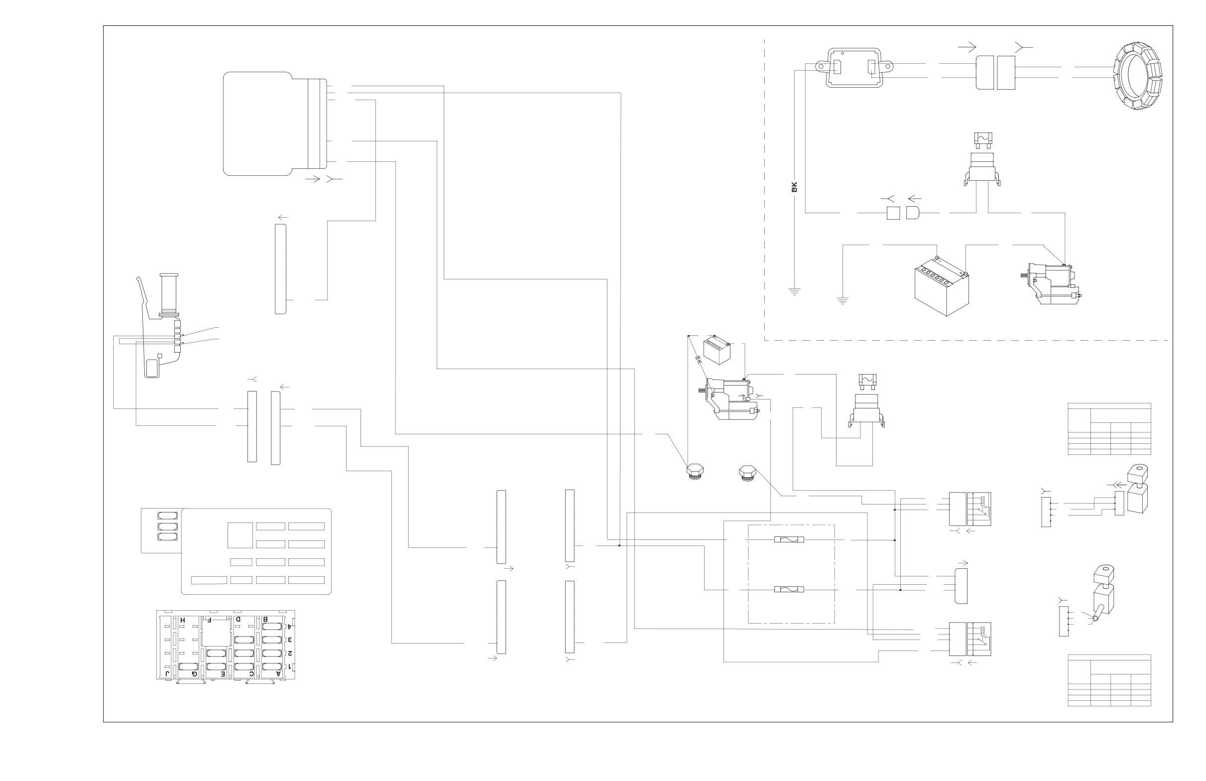
2004 FLHT, FLHTC, FLHTCU and FLTR, DOMESTIC and INTERNATIONAL Models,
Starting and Charging
8-49