Harley Davidson 2004 Touring Models. Service Manual - page 22
HOME
FLTR WIRE HARNESS CONNECTORS (Continued)
No.
Description
Type
Location
Fig.
[75]
Cruise Roll-Off Switch
Spade Contacts
Right Side of Steering Head
-
[77]
Voltage Regulator
1 - Place Deutsch
Right Lower Frame Tube (Below Transmission Bracket)
-
[78]
Electronic Control Module (ECM) ***
36 - Place Packard
Under Right Side Cover
5
[79]
Crankshaft Position (CKP) Sensor
2 - Place Mini-Deutsch
Bottom of Voltage Regulator
11
[80]
Manifold Absolute Pressure (MAP) Sensor
3 - Place Packard
Top of Intake Manifold/Induction Module
-
[83]
Ignition Coil
4 - Place Packard
Below Fuel Tank (Left Side)
-
[84]
Front Injector ***
2 - Place Packard
Below Fuel Tank (Left Side)
-
[85]
Rear Injector ***
2 - Place Packard
Below Fuel Tank (Left Side)
-
[87]
Idle Air Control (IAC) ***
4 - Place Packard
Below Fuel Tank (Right Side)
-
[88]
Throttle Position Sensor (TP Sensor) ***
3 - Place Packard
Below Fuel Tank (Right Side)
-
[89]
Intake Air Temperature Sensor (IAT Sensor) ***
2 - Place Packard
Below Fuel Tank (Right Side)
-
[90]
Engine Temperature Sensor (ET Sensor) ***
2 - Place Packard
Back of Front Cylinder (Left Side)
-
Continued ...
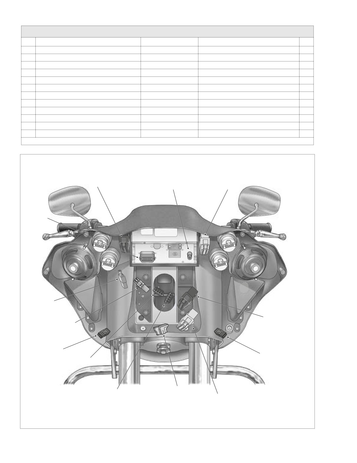
Right Handlebar
Left Handlebar
Radio Antenna
Switch Controls [22]
Switch Controls [24]
Cable [51]
Radio [27]
Radio
Ground
Main to Interconnect
Harness [1]
Main to Interconnect
Harness [156]
Right Turn
Signal [31R]
Ignition
Left Turn
Signal [31L]
Switch [33]
Headlamp [38]
Main to Interconnect
Harness [15]
Main to Interconnect
Harness [2]
f2230x2x
Figure 8-16. Inner Fairing Connectors (FLTR)
8-10
2004 Touring: Wiring

HOME
FLTR WIRE HARNESS CONNECTORS (Continued)
No.
Description
Type
Location
Fig.
[91]
Data Link
4 - Place Deutsch
Under Right Side Cover
5
[93]
Tail Lamp
4 - Place Multilock
Circuit Board Under Tail Lamp Assembly
10
[94]
Rear Fender Lights Harness to Circuit Board
6 - Place Multilock
Circuit Board Under Tail Lamp Assembly
10
Instrument Nacelle Switches
[105]
[105A, 105B]
Interconnect to Nacelle Switch Harness
12 - Place Multilock
Inside Instrument Nacelle (Under Bezel)
15
[105C, 105D]
Nacelle Switch Harness to Speaker Switch
4 - Place Multilock
Inside Instrument Nacelle (Under Bezel)
15
[107]
Ambient Air Temperature Sensor
3 - Place Multilock
Inside Instrument Nacelle (Under Bezel)
15
[108]
Tachometer
12 - Place Packard
Inside Instrument Nacelle (Back of Tachometer)
15
[110]
Voltmeter Lamp
Spade Connector
Inner Fairing
-
[111]
Voltmeter
Spade Connector
Inner Fairing
-
[112]
Oil Pressure Gauge Lamp
Spade Connector
Inner Fairing
-
[113]
Oil Pressure Gauge
Spade Connector
Inner Fairing
-
[114]
Air Temperature Gauge Lamp
Spade Connector
Inner Fairing
-
[115]
Air Temperature Gauge
Spade Connector
Inner Fairing
-
[116]
Fuel Gauge Lamp
Spade Connector
Inner Fairing
-
[117]
Fuel Gauge
Spade Connector
Inner Fairing
-
[119]
EFI Fuses ***
Fuse Terminals
Fuse Block (Under Right Side Cover)
5
[121]
Rear Brake Light Switch
Spade Terminals
Beneath Transmission (Right Side)
-
[122]
Horn
Spade Terminals
Between Cylinders (Left Side)
-
[123]
Starter Relay
Relay Connector
Rear of Battery Box (Under Seat) - Left Side
7
[124]
Brake Light Relay
Relay Connector
Fuse Block (Under Left Side Cover)
4
[126]
Ignition Keyswitch Relay
Relay Connector
Rear of Battery Box (Under Seat) - Left Side
7
[128]
Starter Solenoid
Spade Terminals
Top of Starter
-
[129]
Harness Grounds
Ring Terminals
Upper Frame Cross Member (Under Seat)
6
[131]
Neutral Switch
Post Terminals
Transmission Top Cover
-
[132]
Cigarette Lighter
Spade Terminals
Inner Fairing
-
[135]
EFI System Relay ***
Relay Connector
Fuse Block (Under Right Side Cover)
5
[139]
Oil Pressure Sender
4 - Place Packard
Front Right Crankcase
-
[141]
Fuel Level Sender (and Fuel Pump on EFI models)
3 - Place Mini-Deutsch
Top of Canopy (Under Console)
-
[142]
Security Siren (Optional)
3 - Place Packard
Under Right Side Cover (Behind Electrical Bracket)
5
[156]
Main to Interconnect Harness
6 - Place Deutsch
Inner Fairing - Front of Right Fairing Bracket
16
[160]
B+
1 - Place Packard
Upper Frame Cross Member (Under Seat)
6
*** Fuel Injected Models
**** Carbureted Models
2004 Touring: Wiring
8-11
HOME
NOTES
8-12
2004 Touring: Wiring
HOME
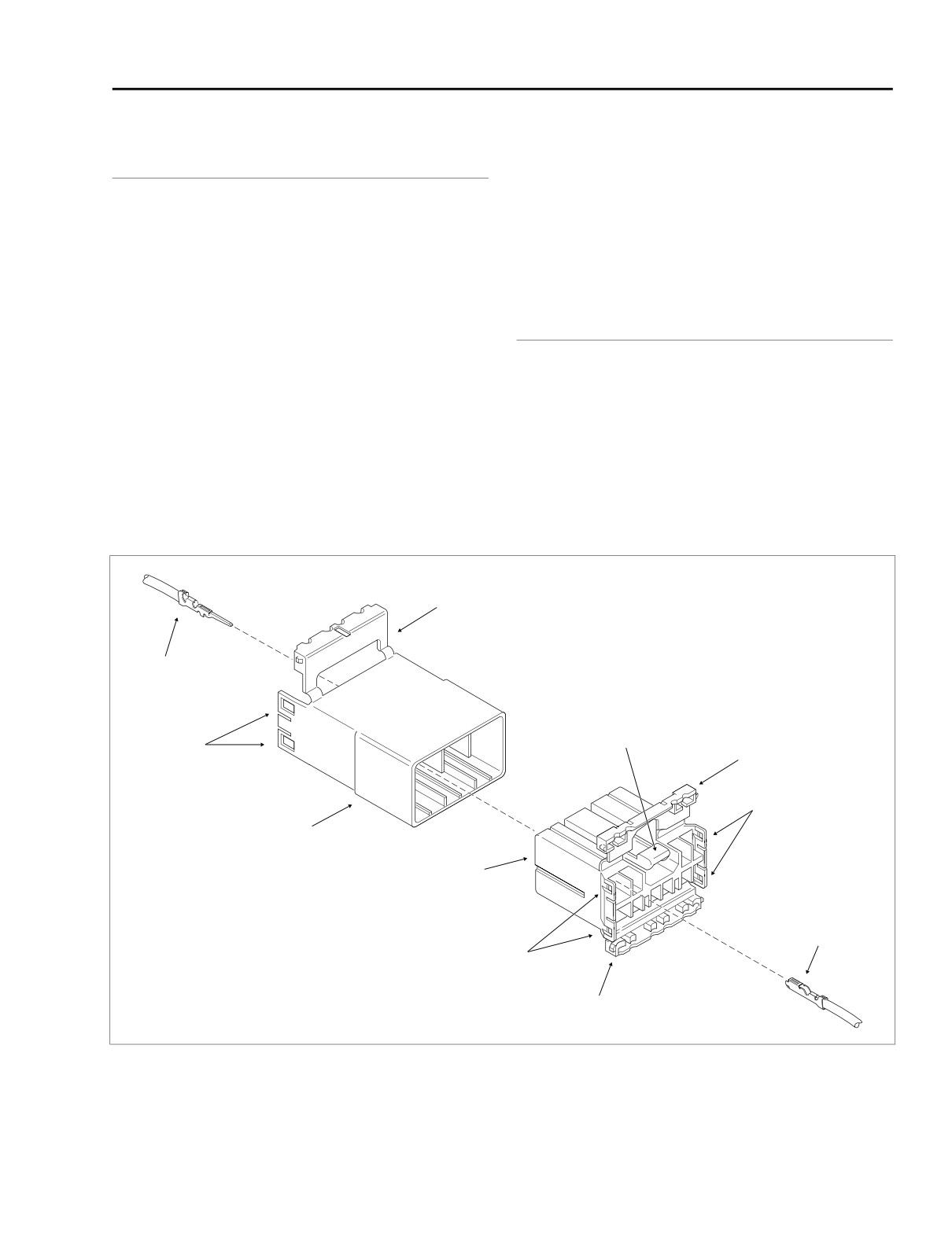
DEUTSCH ELECTRICAL CONNECTORS
8.2
GENERAL
f1049a8x
Attachment clips are attached to the pin housings of some
connectors. The clips are then attached to T-studs on the
motorcycle frame. T-studs give positive location to electrical
connectors and wire harnesses. Consistent location reduces
electrical problems and improves serviceability.
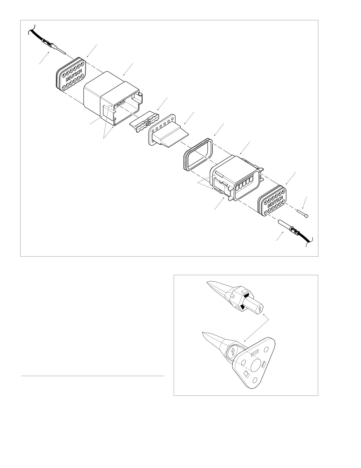
To become familiar with the Deutsch connector, read the
parts description below while referencing the 12-place con-
nector illustrated in Figure 8-19.
Socket housing: alignment tabs and/or external latch, sec-
ondary locking wedge, internal seal, wire seal, seal pin.
NOTE
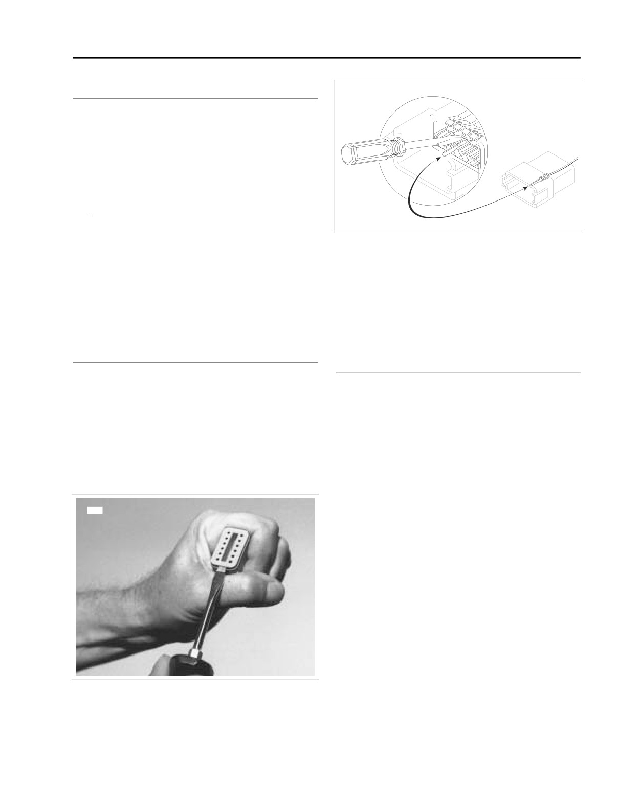
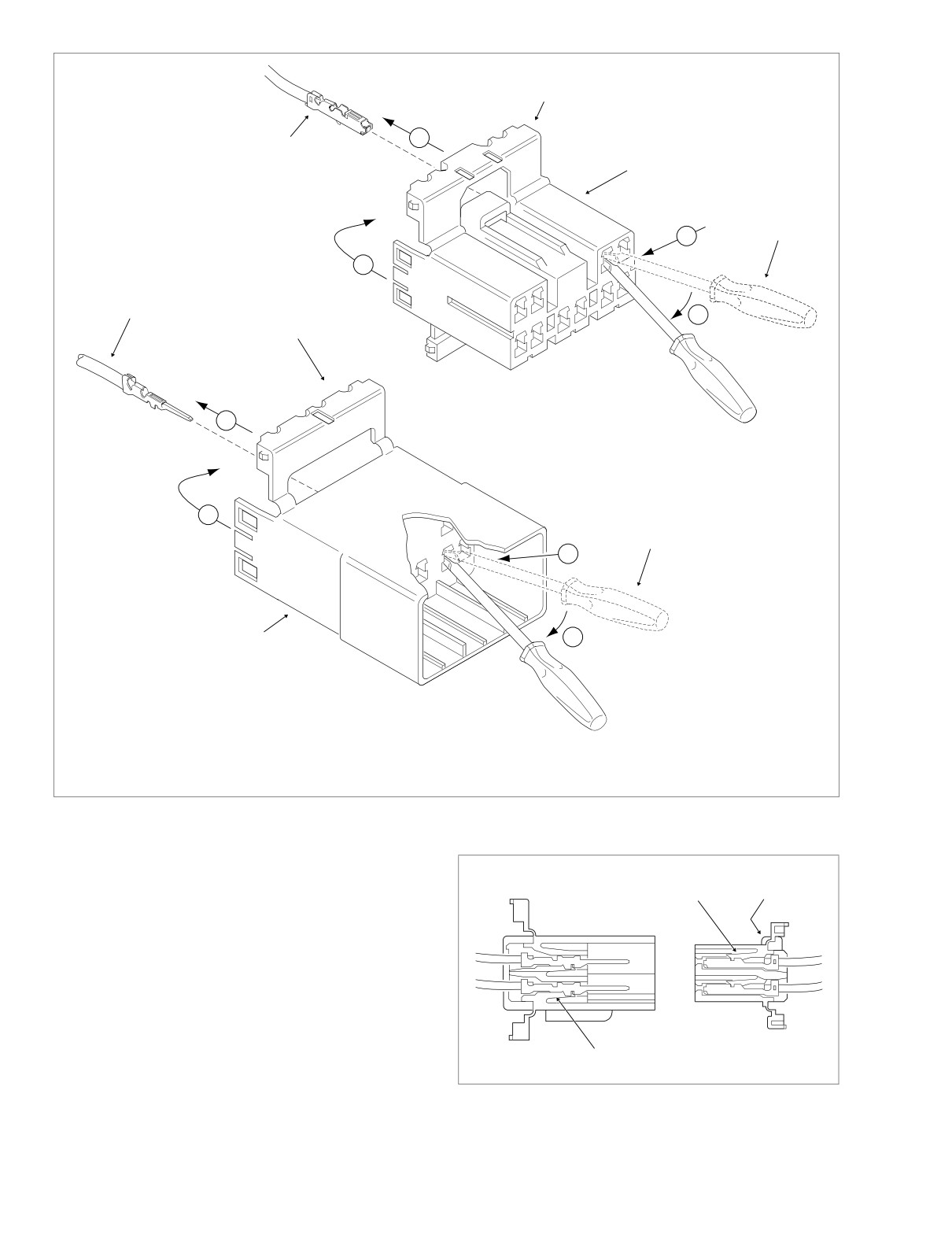
Figure 8-18. Depress Terminal Latches/Back Out Pins
Seal pins or plugs are installed in the wire seals of unused
chambers. If removed, seal pins must be replaced to main-
NOTE
tain the integrity of the environmental seal.
With few exceptions, the socket housing can always be found
Pin housing: alignment grooves and/or external latch cover,
on the accessory side, while the pin side of the connector is
secondary locking wedge, wire seal, seal pin.
plumbed to the wiring harness.
REMOVING/DISASSEMBLING
REMOVING/INSTALLING SOCKETS
1.
Push the connector to disengage small end of slot on
attachment clip fromT-stud. Lift connector off T-stud.
1. See Figure 8-17. Remove the secondary locking wedge.
2.
Depress the external latch(es) on the socket housing
Insert the blade of a small screwdriver between the
side and use a rocking motion to separate the pin and
socket housing and locking wedge inline with the groove
socket halves. Two-, three-, four- and six-place Deutsch
(inline with the pin holes if the groove is absent). Turn the
connectors have one external latch, while eight- and
screwdriver 90 degrees to pop the wedge up.
twelve-place connectors have two, both of which must
be pressed simultaneously to separate the connector
2. Gently depress terminal latches inside socket housing
halves.
and back out sockets through holes in rear wire seal.
See Figure 8-18.
NOTE
4566
If new terminals must be installed, see CRIMPING
INSTRUCTIONS in this section.
3. Fit rear wire seal into back of socket housing, if removed.
Grasp socket approximately 1 inch (25.4 mm) behind the
contact barrel. Gently push sockets through holes in wire
seal into their respective chambers. Feed socket into
chamber until it “clicks” in place. Verify that socket will
not back out of chamber; a slight tug on the wire will con-
firm that it is properly locked in place.
4. Install internal seal on lip of socket housing, if removed.
Insert tapered end of secondary locking wedge into
socket housing and press down until it snaps in place.
The wedge fits into the center groove within the socket
housing and holds the terminal latches tightly closed.
Figure 8-17. Remove Secondary Locking Wedge
2004 Touring: Wiring
8-13
HOME
f1915x8x
Wire Seal
Pin
Housing
Pin
Terminal
Locking Wedge
(Pin Side)
Locking Wedge
(Socket Side)
Internal
Seal
Latch Cover
Socket
Housing
Alignment
Grooves
Wire
Seal
Alignment
Tabs
Seal
NOTE
Pin
For exploded views of 2-place,
3-place and
4-place Deutsch
connectors, see Figure 8-21.
External
Latch
Socket
Terminal
Figure 8-19. 12-Place Deutsch Connector (Exploded View)
NOTE
While rectangular wedges do not require a special orienta-
tion, the conical secondary locking wedge of the 3-place con-
nector must be installed with the arrow pointing toward the
Pin
Housing
external latch. See Figure 8-20.
NOTE
If the secondary locking wedge does not slide into the
Arrow Points to
installed position easily, verify that all terminals are fully
External Latch
installed in the socket housing. The lock indicates when ter-
minals are not properly installed by not entering its fully
installed position.
Socket
Housing
REMOVING/INSTALLING PINS
1. Remove the secondary locking wedge. Use the hooked
f1515x8x
end of a stiff piece of mechanics wire, a needle nose pli-
ers or a suitable pick tool (HD-41475-100). See Figure
Figure 8-20. 3-Place Locking Wedge Orientation
8-22.
8-14
2004 Touring: Wiring
HOME
f1510x8x
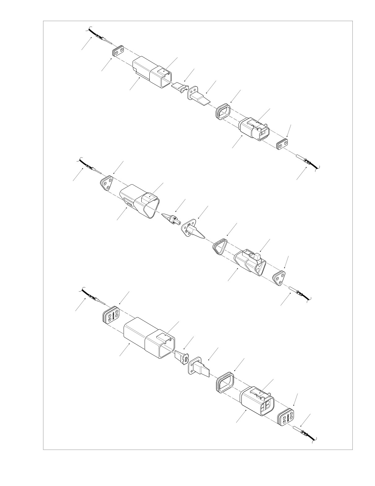
11
8
7
10
6
5
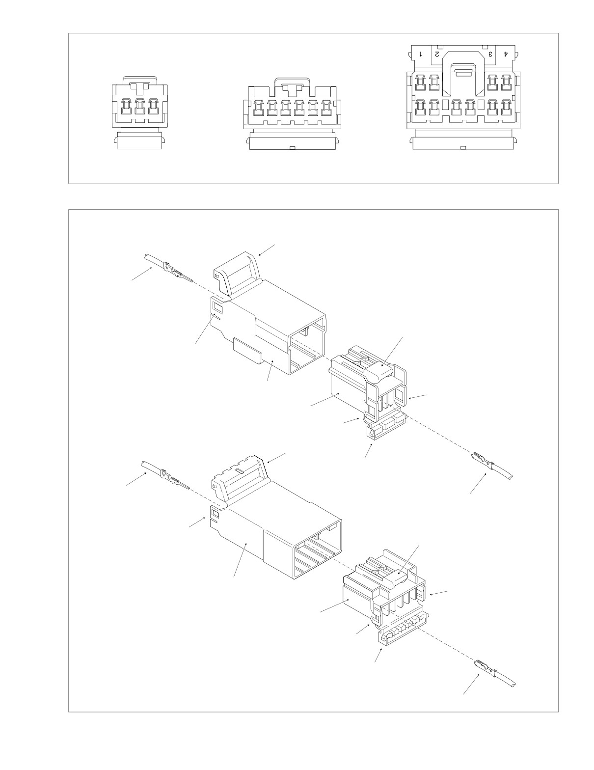
2-Place Connector
9
4
2
3
10
8
11
1
7
6
5
9
3-Place Connector
4
2
3
10
1
11
8
7
6
5
9
4-Place Connector
4
2
Socket Side
Pin Side
12. Socket Terminal
18. Locking Wedge
13. Wire Seal
19. Latch Cover
1
14. Socket Housing
20. Pin Housing
15. External Latch
21. Wire Seal
3
16. Internal Seal
22. Pin Terminal
17. Locking Wedge
Figure 8-21. 2-Place, 3-Place and 4-Place Deutsch Connectors
2004 Touring: Wiring
8-15
HOME
click (latch), press on one side of the connector until that
latch engages, then press on the opposite side to
engage the other latch.
NOTES
●
Deutsch connectors are colored coded for location pur-
poses. Those connectors associated with left side
accessories, such as the front and rear left turn signals,
Figure 8-22. Deutsch Connector Pick Tool
are gray. All other connectors, including those associ-
(Part No. HD-41475-100)
ated with right side accessories, are black.
●
If it should become necessary to replace a plug or
2.
Gently depress terminal latches inside pin housing and
receptacle, please note that the 8-place and 12-place
back out pins through holes in wire seal.
gray and black connectors are not interchangeable.
Since location of the alignment tabs differ between the
NOTE
black and gray connectors, plugs or receptacles must be
If new terminals must be installed, see CRIMPING
replaced by those of the same color. If replacing both the
INSTRUCTIONS on this page.
socket and pin halves, then the black may be substituted
for the gray, and vice versa. The socket and pin halves of
3.
Fit wire seal into back of pin housing. Grasp crimped pin
all other connectors are interchangeable, that is, the
approximately 1 inch (25.4 mm) behind the contact bar-
black may be mated with the gray, since the alignment
rel. Gently push pins through holes in wire seal into their
tabs are absent and the orientation of the external latch
respective numbered locations. Feed pin into chamber
is the same.
until it “clicks” in place. Verify that pin will not back out of
chamber; a slight tug on the wire will confirm that it is
2.
Fit the attachment clip to the pin housing, if removed.
properly locked in place.
Place large end of slot on attachment clip over T-stud on
4.
Insert tapered end of secondary locking wedge into pin
frame. Push assembly forward to engage small end of
housing and press down until it snaps in place. The
slot.
wedge fits in the center groove within the pin housing
and holds the terminal latches tightly closed.
NOTE
CRIMPING INSTRUCTIONS
While rectangular wedges do not require a special orienta-
tion, the conical secondary locking wedge of the 3-place con-
Use the Deutsch Terminal Crimp Tool (HD-39965) to install
nector must be installed with the arrow pointing toward the
standard size terminals with crimp tails, as described under
external latch. See Figure 8-20.
STANDARD TERMINALS below. To install the mini-Deutsch
NOTE
terminals with crimp tails, see MINI TERMINALS, which fol-
lows. To install those terminals without crimp tails, both stan-
If the secondary locking wedge does not slide into the
dard and mini-Deutsch, use the Deutsch Solid Barrel Contact
installed position easily, verify that all terminals are fully
Crimp Tool (HD-42879) as described under SOLID BARREL
installed in the pin housing. The lock indicates when termi-
CONTACTS.
nals are not properly installed by not entering its fully
installed position.
NOTE
A Deutsch Connector Service Kit (HD-41475) contains a
selection of wire seals, internal seals, seal plugs, secondary
ASSEMBLING/INSTALLING
locking wedges, attachment clips and socket/pin terminals.
Also included is a compartmented storage box, carrying case
1. Insert socket housing into pin housing until it snaps in
and pick tool (HD-41475-100) used for the removal of all
place. Two-, three-, four- and six-place Deutsch connec-
types of locking wedges.
tors have one external latch on the socket half of the
connector. To fit the halves of the connector together, the
latch on the socket side must be aligned with the latch
Standard Terminals
cover on the pin side.
For those connectors with two external latches (8-place
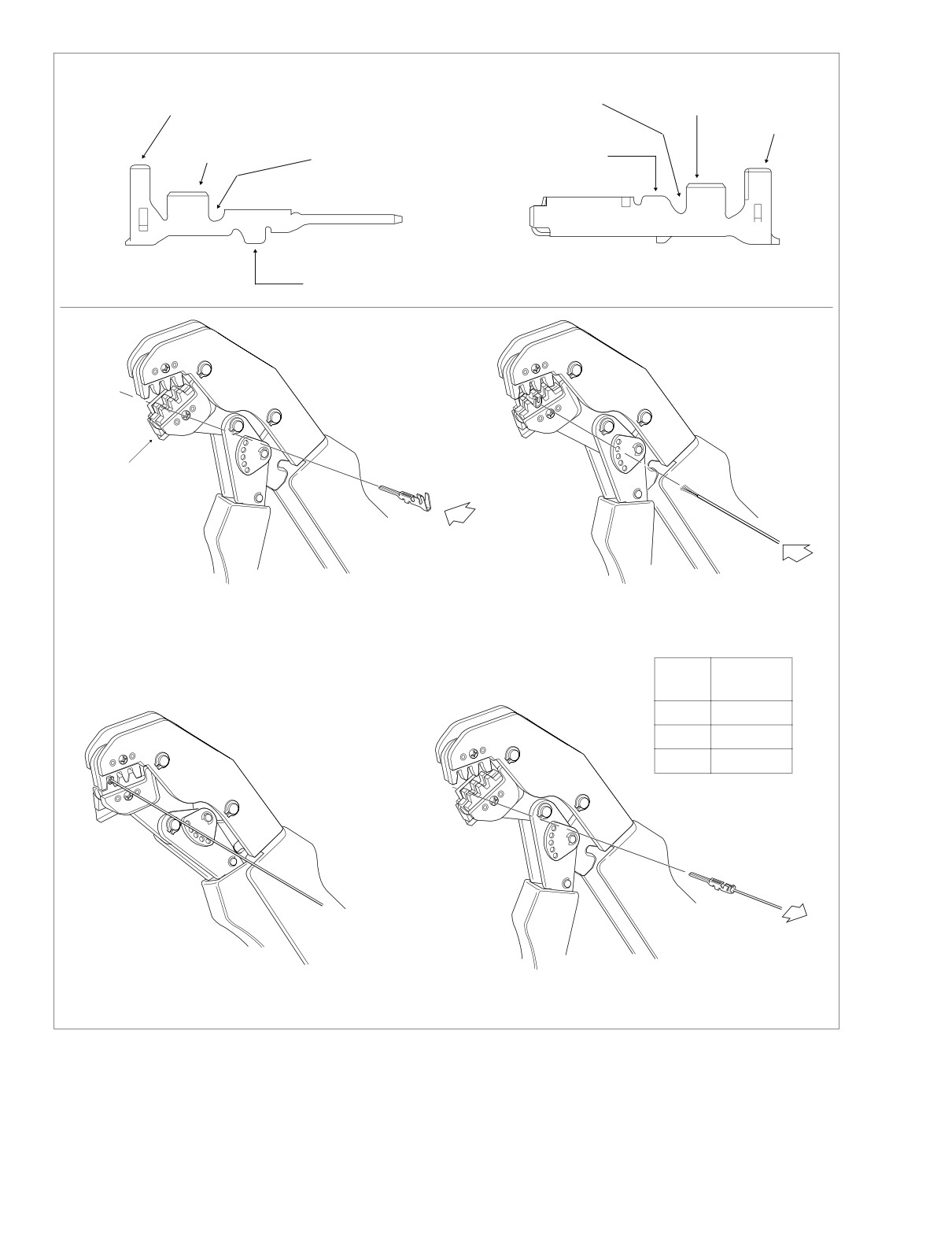
1. Obtain the DEUTSCH TERMINAL CRIMP TOOL (HD-
and 12-place), a different system is used to prevent
39965).
improper assembly. Align the tabs on the socket housing
2. Squeeze the handles to cycle the crimp tool to the fully
with the grooves on the pin housing. Push the connector
open position. See Figure 8-23.
halves together until the latches “click.” If latches do not
8-16
2004 Touring: Wiring
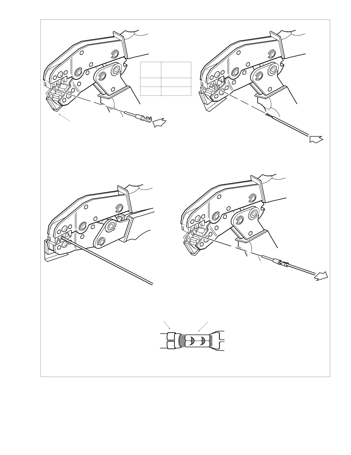
HOME
f1516x8x
1.
2.
Gauge
Nest of
Wire
Crimp Tool
20
Front
16-18
Middle
Locking
Bar
1. Insert contact through hole of locking bar
2. Insert stripped lead until it contacts
so that barrel rests on nest of crimp tool.
locking bar.
3.
4.
3. Close and squeeze crimp tool.
4. Raise locking bar and remove contact.
Insulation crimp
Core crimp
5.
5. Inspect quality of core and insulation crimps.
f1558x8x
Figure 8-23. Deutsch Crimping Procedure
2004 Touring: Wiring
8-17
HOME
3.
Raise the locking bar by pushing up on bottom flange.
Solid Barrel Contacts
With the crimp tails facing upward, insert contact
(socket/pin) through hole of locking bar, so that the
For Size 20, 16 and 12 Contacts
rounded side of the contact barrel rests on the nest (con-
Wire Range 26-12 AWG
cave split level area) of the crimp tool. Use the middle
hole in the locking bar for 16-18 gauge wire, the front
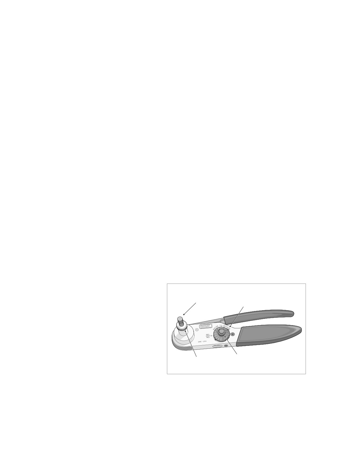
1.
Obtain the DEUTSCH SOLID BARREL CONTACT
hole for 20 gauge wire.
CRIMP TOOL (HD-42879).
4.
Release locking bar to lock position of contact. If the
2.
Squeeze the handles to cycle the crimp tool to the fully
crimp tails are slightly out of vertical alignment, the crimp
open position.
tool automatically rotates the contact so that the tails
face straight upward. When correctly positioned, the
3.
Remove locking pin from selector knob. See Figure 8-
locking bar fits snugly in the space between the contact
24.
band and the core crimp tails.
4.
Raise selector knob and rotate until selected wire size
5.
Strip lead removing 5/32 inch (4.0 mm) of insulation.
stamped on wheel is aligned with “SEL. NO.” arrow. See
Insert wires between crimp tails until ends make contact
upper frame of Figure 8-25.
with locking bar. Verify that wire is positioned so that
5.
Loosen knurled locknut and turn adjusting screw clock-
short pair of crimp tails squeeze bare wire strands, while
wise (in) until it stops.
long pair folds over insulation material.
6.
Squeeze handle of crimp tool until tightly closed. Tool
6.
Turn tool over and drop contact into indentor cover hole
automatically opens when the crimping sequence is
with the wire end out.
complete. Raise up locking bar and remove contact.
7.
Turn adjusting screw counterclockwise (out) until contact
7.
Inspect the quality of the core and insulation crimps. Dis-
is flush with bottom of depression in indentor cover.
tortion should be minimal.
Tighten knurled locknut.
8.
Slowly squeeze handles of crimp tool until contact is
centered between indentor points. See middle frame of
Figure 8-25.
Mini Terminals
9.
Strip wire lead removing 1/4 inch (6.4 mm) of insulation.
1.
Obtain the PACKARD TERMINAL CRIMP TOOL (HD-
10.
Insert bare wire strands into contact barrel. See lower
38125-7).
frame of Figure 8-25.
2.
Strip wire lead removing 5/32 inch (4.0 mm) of insula-
tion.
11.
Squeeze handle of crimp tool until tightly closed. Tool
automatically opens when the crimping sequence is
3.
Compress handles until ratchet automatically opens.
complete.
NOTE
12.
Remove crimped contact from indentor.
Always perform core crimp before insulation crimp.
13.
Inspect the quality of the crimp. Verify that all wire
4.
Position the core crimp on nest E of the crimping tool. Be
strands are in crimp barrel.
sure the core crimp tails are facing the forming jaws.
5.
Gently apply pressure to handles of tool until crimpers
just secure the core crimp tails.
6.
Insert stripped wire between crimp tails. Verify that wire
Adjusting
is positioned so that short pair of crimp tails squeeze
Locking
Screw
bare wire strands, while long pair is positioned over the
Pin
insulation material.
7.
Squeeze handle of crimp tool until tightly closed. Tool
automatically opens when the crimping sequence is
complete.
8.
Position the insulation crimp on nest C of the crimping
tool. Be sure the insulation crimp tails are facing the
forming jaws.
Selector
9.
Squeeze handle of crimp tool until tightly closed. Tool
Locknut
Knob
f1535x8x
automatically opens when the crimping sequence is
complete.
Figure 8-24. Deutsch Solid Barrel Contact Crimp Tool
10.
Inspect the quality of the core and insulation crimps. Dis-
(Part No. HD-42879)
tortion should be minimal.
8-18
2004 Touring: Wiring
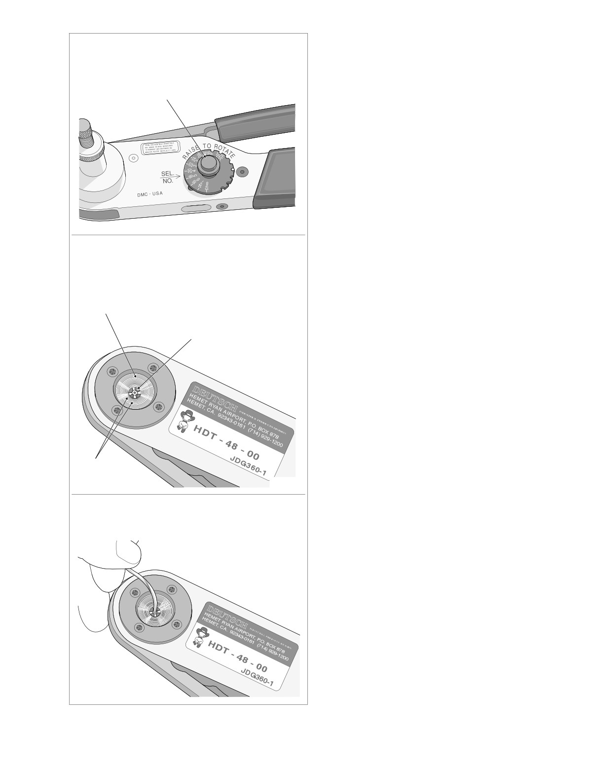
HOME
NOTE
Rotate selector knob to align wire size on wheel
with arrow stamped in tool.
Tool must be readjusted when changing contact size/type.
14. Install pin to lock position of selector knob.
Selector
Knob
f1534x8x
Turn adjusting screw as described in text. When
contact is flush with bottom of depression in
indentor cover, squeeze handles to center contact
between indentor points.
Indentor
Cover
Contact
Indentor
Points
f1532x8x
Insert bare wire strands into contact barrel.
Squeeze handle of crimp tool until tightly closed.
f1533x8x
Figure 8-25. Deutsch Solid Barrel Contact
Crimping Procedure
2004 Touring: Wiring
8-19
HOME
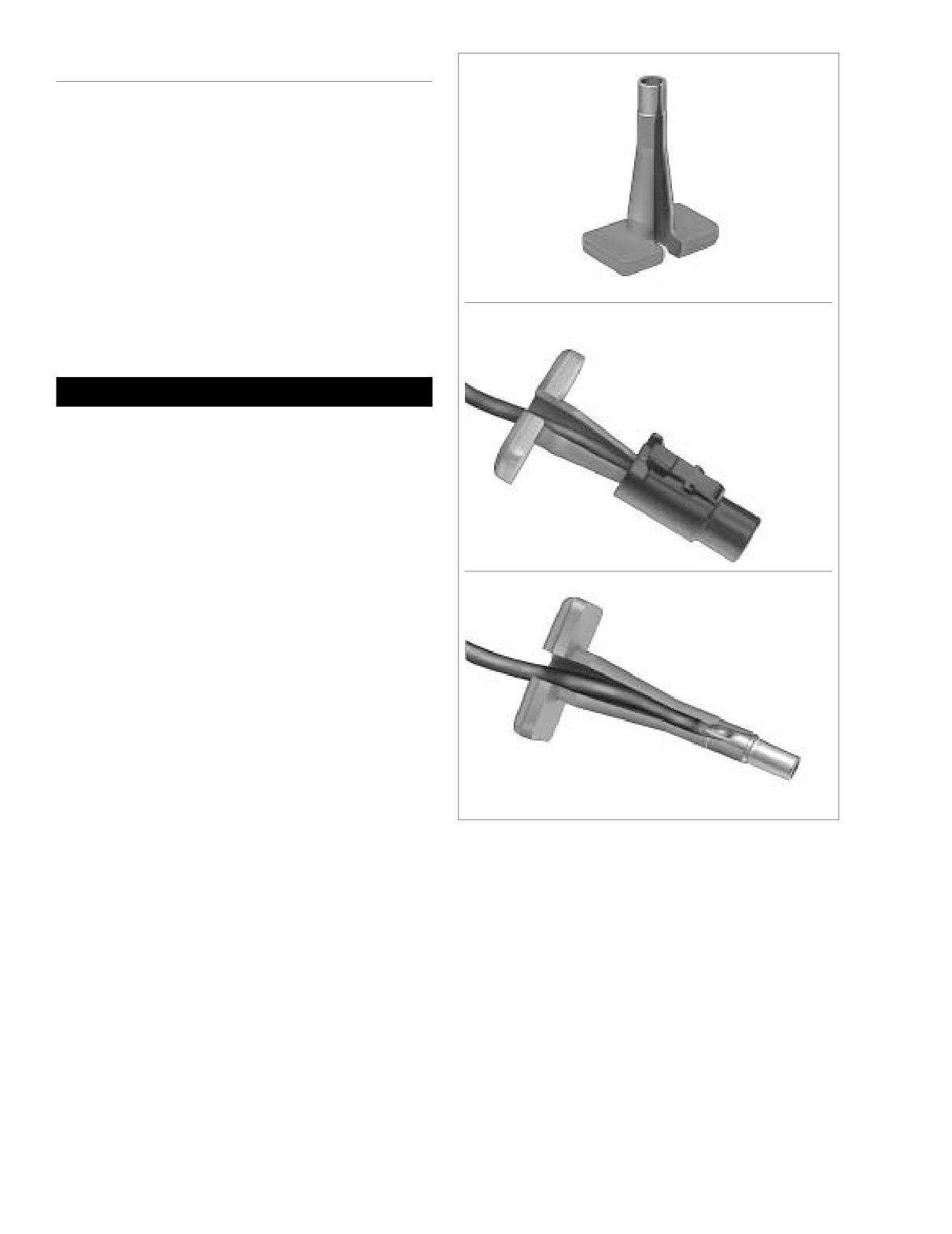
1-PLACE CABLE CONNECTOR
A
General
Use the following instructions to service the voltage regulator
cable connector.
Removal
1. Depress external latch and separate pin and socket
halves of connector.
7786
2. Pull rear wire seal from back of housing and slide down
voltage regulator cable to move out of the way.
3. Obtain terminal pick tool (Deutsch® 114008) like that
B
shown in A of Figure 8-26.
CAUTION
Rough handling or careless storage can result in tool
damage. Exercise care to avoid cracking or breaking the
thin plastic construction.
4.
Install terminal pick tool onto voltage regulator cable so
that the tapered end is in the wire end of the housing.
See B of Figure 8-26.
7787
5.
Push tool into wire end of housing until it bottoms. Gen-
tly tug on housing to pull from terminal. See C of Figure
8-26.
C
6.
Remove tool from voltage regulator cable.
Installation
1.
Insert terminal into wire end of housing until it “clicks” in
place. Verify that terminal will not back out of housing. A
slight tug on the voltage regulator cable will confirm that
it is properly locked in place.
2.
Fit rear wire seal into back of housing.
3.
Mate pin and socket halves of connector.
7788
Figure 8-26. Remove Socket/Pin Housing
8-20
2004 Touring: Wiring
HOME
AMP MULTILOCK ELECTRICAL CONNECTORS
8.3
is engaged but then inadvertently released. Repeat the
REMOVING SOCKET/PIN
step without releasing the tang.
TERMINALS
NOTE
1. Remove connector from the retaining device, either
An Electrical Terminal Crimp Tool (Part No. HD-41609) is
attachment or rosebud clip.
used to install Amp Multilock pin and socket terminals on
wires. If new terminals must be installed, see CRIMPING
2. Depress the button on the socket terminal side of the
INSTRUCTIONS in this section.
connector
(plug) and pull apart the pin and socket
halves. See Figure 8-27.
3. Bend back the latch slightly and free one side of second-
INSTALLING SOCKET/PIN
ary lock, then repeat the step to release the other side.
Rotate the secondary lock outward on hinge to access
TERMINALS
terminals in chambers of connector housing.
4. Looking in the terminal side of the connector (opposite
NOTE
the secondary lock), take note of the cavity next to each
For wire location purposes, numbers are stamped into the
terminal.
secondary locks of both the socket and pin housings. See
5. See Figure 8-28. With the flat edge against the terminal,
Figure 8-30.
insert the pick (Snap-On TT600-3) into the cavity until it
stops. Pivot the end of the pick away from the terminal
1.
From the secondary lock side of the connector, insert the
and gently tug on wire to pull terminal from chamber. Do
terminal into its respective numbered chamber until it
not tug on the wire until the tang is released or the termi-
snaps in place. For proper fit, the slot in the terminal
nal will be difficult to remove. A “click” is heard if the tang
must face the tang in the chamber.
Secondary Lock
NOTE
Open
For exploded views of 3-place
and
6-place Amp Multilock
connectors, see Figure 8-31.
Pin Terminal
Button
Secondary Lock
Latch
Open
Latch
Pin Housing
Socket Housing
Socket Terminal
Latch
Secondary Lock
f1292x2x
Open
Figure 8-27. 10-Place Amp Multilock Connector (Exploded View)
2004 Touring: Wiring
8-21
HOME
Secondary Lock
Open
f1289x2x
4
Socket Terminal
Socket Housing
Pick Tool
2
1
Pin Terminal
Secondary Lock
3
Open
4
1
Pick Tool
2
Pin Housing
3
1. Open Secondary Lock.
2. Insert Pick into Cavity on Mating End of Connector.
3. Pivot End of Pick to Release Tang.
4. Gently Tug on Wire to Remove Terminal from Housing.
Figure 8-28. Release Tang and Back Out Terminals
NOTE
The tang in the chamber engages the slot to lock the terminal
Pin Housing
Tang
Button
in position. On the pin side of the connector, tangs are posi-
tioned at the bottom of each chamber, so the slot in the pin
terminal (on the side opposite the crimp tails) must face
downward. On the socket side, tangs are at the top of each
chamber, so the socket terminal slot (on the same side as the
crimp tails) must face upward. Up and down can be deter-
mined by the position of the release button (used to separate
the pin and socket halves), the button always being the top of
the connector. See Figure 8-29.
2. Gently tug on wire end to verify that the terminal is
Tang
Socket Housing
f1428x8x
locked in place and will not back out of chamber.
Figure 8-29. Tang Location (Cross Sectional View)
8-22
2004 Touring: Wiring
HOME
f1287x2x
Secondary Locks Open
- AMP
- AMP
1
2
3
1
2
3
4
5
6
5
6
7
8
9
10
3-Place Connector
6-Place Connector
10-Place Connector
Figure 8-30. Numbers Stamped on Secondary Locks for Wire Color Locations (Socket Housings Shown)
f1291x2x
3-Place Connector
8
9
5
7
6
3
4
3
6-Place Connector
8
2
9
1
7
5
Socket Side
23. Socket Terminal
6
3
24. Secondary Lock (Open)
25. Latch
26. Socket Housing
4
27. Button
3
Pin Side
28. Pin housing
29. Latch
2
30. Secondary Lock (Open)
31. Pin Terminal
f1288x2x
1
Figure 8-31. 3-Place and 6-Place Amp Multilock Connectors
2004 Touring: Wiring
8-23
HOME
Locking Bar
f1286x2x
Insulation
Core
Groove
Crimp Tail
Crimp Tail
Insulation
Crimp Tail
Core
Locking Bar
Crimp Tail
Groove
Tang Slot
PIN TERMINAL
Tang Slot
SOCKET TERMINAL
f1290a2x
1.
2.
Locking
Bar
1. Raise locking bar and seat contact on nest
2. Insert stripped lead until it contacts
of crimp tool. Release locking bar.
locking bar.
Gauge
Nest of
3.
4.
Wire
Crimp Tool
20
Front
16
Middle
18
Rear
3. Close and squeeze crimp tool.
4. Raise locking bar and remove contact.
Figure 8-32. Amp Multilock Crimping Procedure
8-24
2004 Touring: Wiring
HOME
3.
Rotate the hinged secondary lock inward until tabs fully
CRIMPING INSTRUCTIONS
engage latches on both sides of connector.
4.
Insert the socket housing (plug) into the pin housing
1.
Squeeze the handles to cycle the crimp tool (Part No.
(receptacle) until it snaps in place.
HD-41609) to the fully open position.
5.
Install connector on retaining device, either attachment
2.
Raise locking bar by pushing up on bottom flange. With
or rosebud clip.
the crimp tails facing upward, insert contact (socket/pin)
through locking bar, so that the closed side of the con-
tact rests on the nest (concave split level area) of the
crimp tool). Use the front nest for 20 gauge wire, the
middle for 16 gauge and the rear for 18 gauge. See Fig-
ure 8-32.
3.
Release locking bar to lock position of contact. When
correctly positioned, the locking bar fits snugly in the
space at the front of the core crimp tails.
4.
Strip lead removing 5/32 inch (4.0 mm) of insulation.
Insert wires between crimp tails until ends make contact
with locking bar. Verify that wire is positioned so that
short pair of crimp tails squeeze bare wire strands, while
long pair folds over insulation material.
5.
Squeeze handle of crimp tool until tightly closed. Tool
automatically opens when the crimping sequence is
complete. Raise up locking bar and remove contact.
6.
Inspect the quality of the core and insulation crimps. Dis-
tortion should be minimal.
2004 Touring: Wiring
8-25
HOME
PACKARD ELECTRICAL CONNECTORS
8.4
150 METRI-PACK SERIES
General
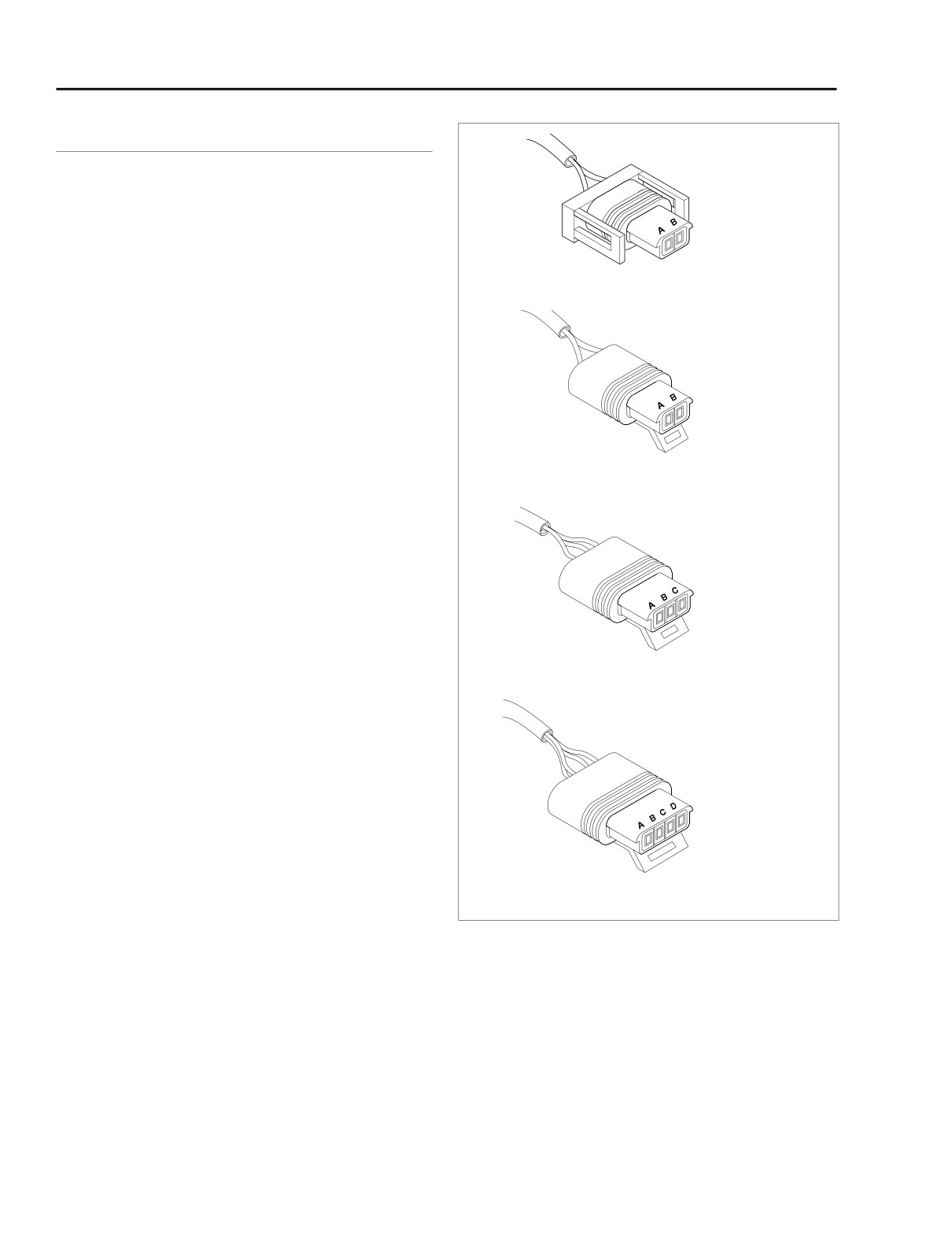
2-Place
Use these instructions to service the following connectors:
● MAP Sensor [80B]
● Ignition Coil [83B/130B]
IAT Sensor Connector [89B]
● IAC Actuator [87B]
● TP Sensor [88B]
● ET Sensor [90B]
2-Place
● IAT Sensor [89B]
Disassembly
1.
Remove the connector from the retaining device, if
ET Sensor Connector [90B]
present.
2.
Bend back the external latch(es) slightly and separate
the pin and socket halves of the connector.
3.
To free a pull-to-seat terminal from the connector hous-
ing, first look into the mating end of the connector to find
3-Place
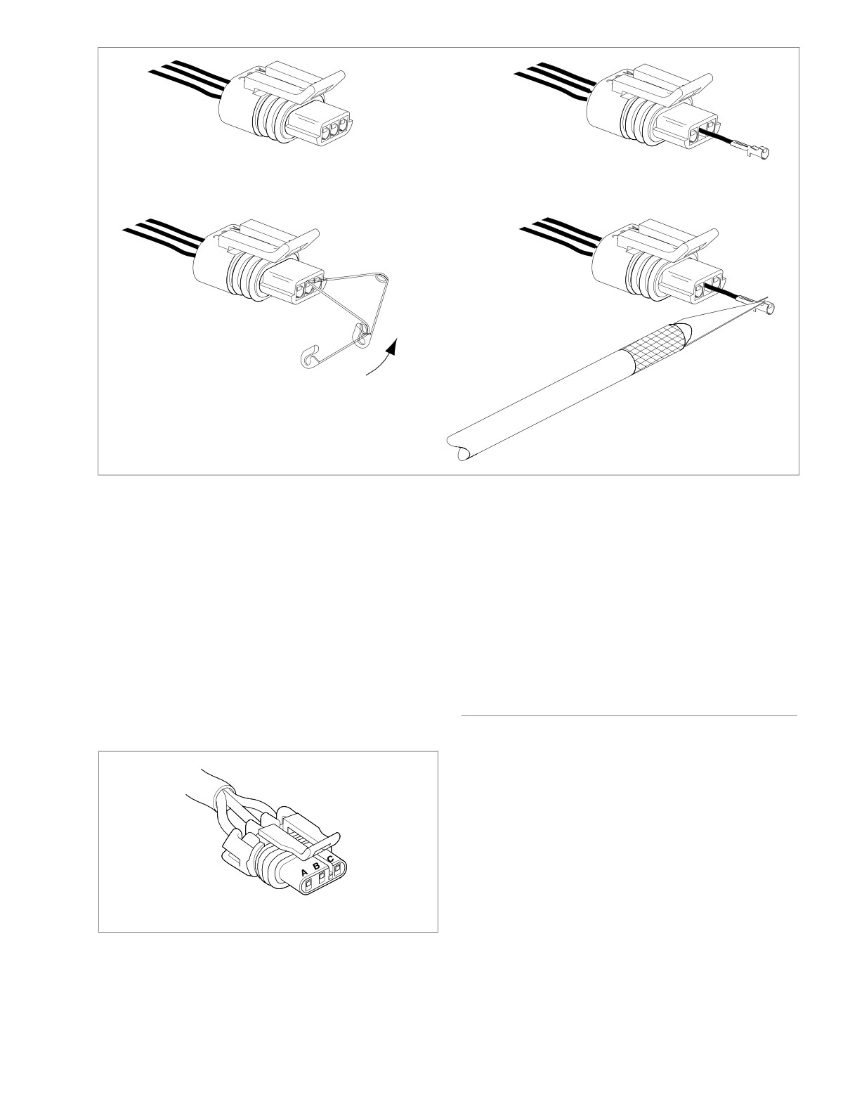
the locking tang. See A in Figure 8-34. The tangs are
always positioned in the middle of the chamber and are
on the same side as the external latch. On those con-
nectors with locking ears, the tang is on the side oppo-
site the ear. See Figure 8-35.
TP Sensor Connector [88B]
4.
At a slight angle, gently insert the point of a one inch
safety pin down the middle of the chamber about 1/8
inch (3.2 mm), and pivot the end of the pin toward the
terminal body. When a click is heard, remove the pin and
repeat the procedure. See B in Figure 8-34. The click is
the sound of the tang returning to the locked position as
4-Place
it slips from the point of the pin. Pick at the tang in this
manner until the clicking stops and the pin seems to
slide in at a slightly greater depth than it had previously.
This is an indication that the tang has been depressed.
NOTE
IAC Connector [87B]
On those terminals that have been extracted on a previous
occasion, no clicking sound may be heard when the pin is
pivoted to depress the tang, but proceed as if the clicking is
Figure 8-33. Packard External Latch Type Connectors
audible and then push on the wire end of the lead to check if
(Socket Sides)
the terminal is free.
NOTE
5.
Remove the pin and push on the wire end of the lead to
When picking multiple terminals, the end of the pin may
extract the terminal from the mating end of the connec-
become malleable. For best results, continue the procedure
tor. See C in Figure 8-34. If necessary, pull back the con-
with a new safety pin.
duit and remove the wire seal at the back of the
connector to introduce some slack in the wires.
8-26
2004 Touring: Wiring
HOME
f1360x8x
A
C
Locate tang on latch side of chamber.
Push on wire end of lead to remove terminal.
B
D
Pivot end of pin to depress tang.
Raise tang and re-install terminal.
Figure 8-34. Depress Tang and Extract Terminal From Mating End of Connector
6. If necessary, crimp new terminals on wires. See Crimp-
2. Gently pull on the lead at the wire end of the connector
ing Instructions at the end of this section.
to draw the terminal back into the chamber. A click is
heard when the terminal is properly seated.
3. Push on the lead to verify that the terminal is locked in
Assembly
place.
NOTE
4. Push the pin and socket halves of the connector
For wire location purposes, alpha characters are stamped
together until the latches “click.”
into the socket housings.
1. Using a thin flat blade, like that on an X-Acto knife, care-
fully bend the tang outward away from the terminal body.
280 METRI-PACK SERIES
See D in Figure 8-34.
General
Use these instructions to service the following:
● Front/Rear Fuel Injectors [84B/85B]
● System Fuse Block [64B]
Fuel Injectors
Disassembly
1. Depress the wireform and use a rocking motion to
detach the electrical connector.
Figure 8-35. Packard Pull-to-Seat Terminal Connector
With Locking Ear
2. Pry rubber seal from wire end of connector and move
seal down wires toward conduit.
2004 Touring: Wiring
8-27
HOME
f2012x9x
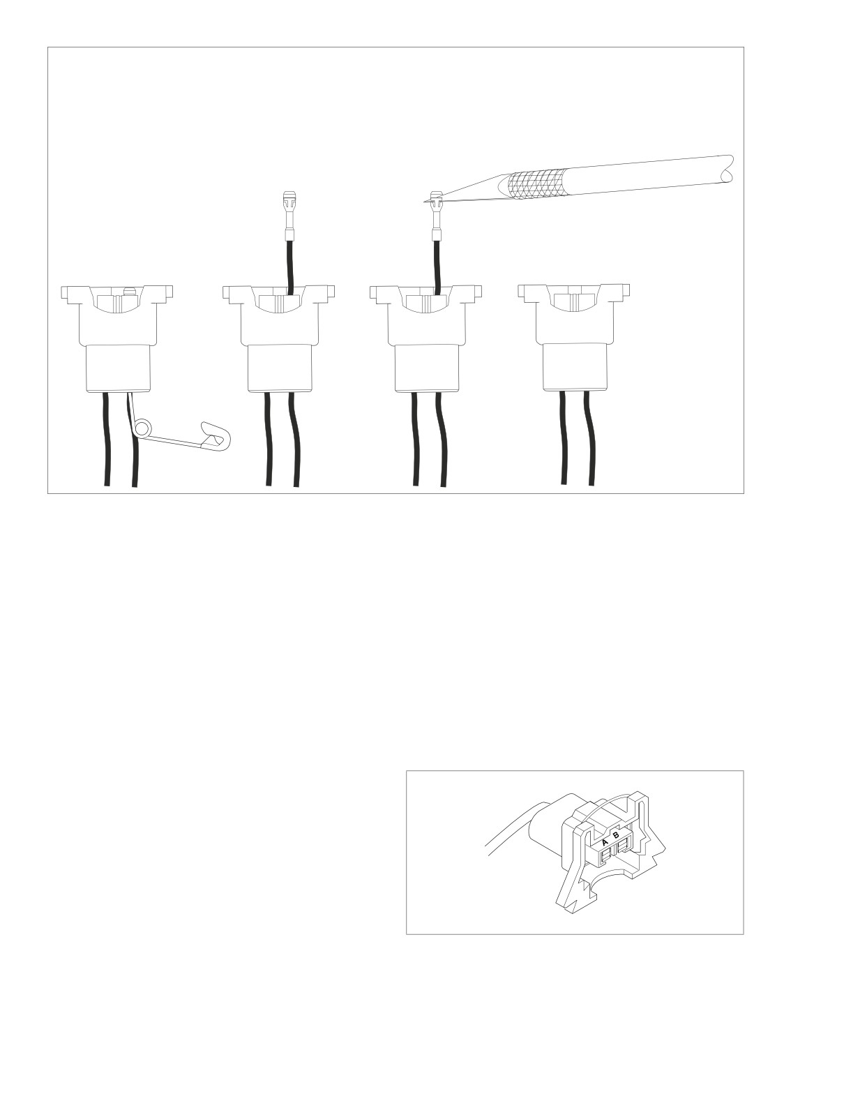
A. Insert safety pin at wire end of
C. Raise tang with blade of X-Acto
connector to depress tang.
knife.
B. Push on wire end of lead to
D. Pull on wire end of lead to draw
remove terminal.
terminal back into chamber.
A
B
C
D
Figure 8-36. Extract/Install Socket Terminal at Mating End of Connector
3.
Hold the connector so that the wireform is facing down,
2.
Gently pull on the lead at the wire end of the connector
and looking into the wire end of the connector, insert the
to draw the terminal back into the chamber. Be sure that
point of a safety pin between the top of the terminal and
the tang faces opposite the wireform as it enters the
the inside chamber wall.
chamber. A “click” is heard when the terminal is properly
4.
Push safety pin completely into chamber while watching
seated. See D in Figure 8-36.
terminal on mating end of connector. When terminal is
3.
Push on lead to verify that terminal is locked in place.
observed moving forward slightly, then tang is
depressed. See A in Figure 8-36. Remove safety pin.
4.
Fit rubber wire seal back into wire end of connector.
NOTE
5.
Push the pin and socket halves of the connector
Repeat steps 3 and 4 as necessary until the desired result is
together until the latch “clicks.” The groove in the socket
achieved.
housing must be aligned with the tab in the pin housing.
5.
Push on wire end of the lead to extract the terminal from
the mating end of the connector. See B in Figure 8-36.
6.
If necessary, crimp new terminals on wires. See Crimp-
ing Instructions at the end of this section.
Assembly
NOTE
For wire color locations, see Section
8.8 WIRING DIA-
GRAMS and then refer to Figure 8-37.
1. Using a thin flat blade, like that on an X-Acto knife, care-
fully bend the tang outward away from the terminal body.
Figure 8-37. Fuel Injector Connector [84B/85B]
See C in Figure 8-36.
8-28
2004 Touring: Wiring
HOME
System Fuse Block
Disassembly
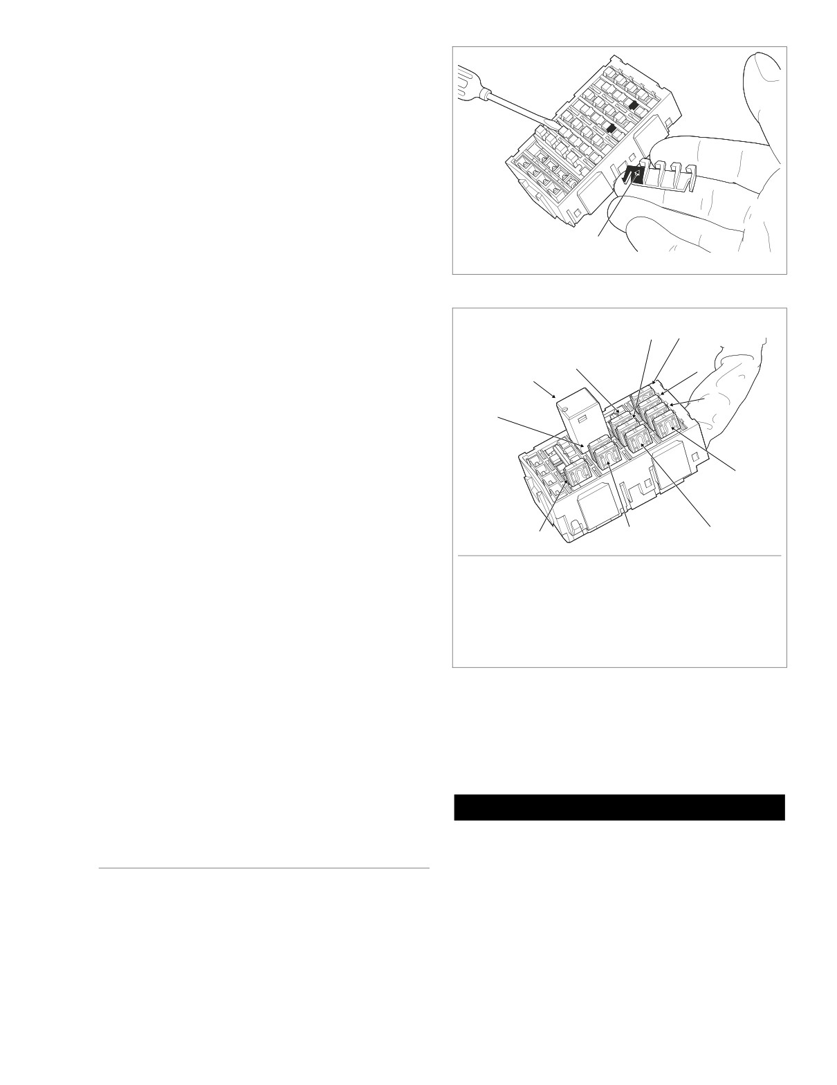
1. Remove system fuses and relay(s) from fuse block.
2. Remove secondary locks as follows:
a. Insert end of small flat blade screwdriver under lip of
locking wedge and gently pry up secondary lock.
NOTE
For best results, start with locking wedge on outboard side of
secondary lock. See Figure 8-38.
Lip of
Locking Wedge
f2205x8x
3. Remove socket terminals as follows:
a. Looking into chamber at top of fuse block, note the
Figure 8-38. Remove Secondary Locks From Fuse Block
tang next to each socket terminal.
b. Using a thin flat blade, like that on an X-Acto knife,
8
7
gently push tang away from terminal, and then tug
on wire to back terminal out wire end of chamber.
9
6
10
4. If necessary, crimp new terminals on wires. See Crimp-
5
ing Instructions at the end of this section.
11
Assembly
4
1.
Install socket terminals as follows:
NOTE
See Section 8.8 WIRING DIAGRAMS, MAIN HARNESS, for
f2204x8x
2
3
1
wire colors and locations.
a. With the open side of the socket terminal facing the
1. Headlamp
7.
Radio Power
tang, push lead into chamber at the wire end of the
2. Ignition
8.
Accessory
fuse block. A click is heard when the terminal is
3. Lighting
9.
Battery
properly engaged.
4. Instruments
10. Brake Light Relay
5. Brakes/Cruise
11. P&A
b. Gently tug on the wire to verify that the terminal is
6. Radio Memory
locked in place and will not back out of the chamber.
Figure 8-39. Fuse Block (FLTR, FLHTC/U)
2.
Install secondary locks as follows:
a. With the locking wedges positioned above the tangs
in each chamber, slide flat side of secondary lock
Disassembly
into slot (between rows), and push down until it bot-
toms. See Figure 8-38.
1.
Remove seat.
3.
Install system fuses and relay(s) in fuse block.
1WARNING
Always disconnect the negative battery cable first. If the
480 METRI-PACK SERIES
positive cable should contact ground with the negative
cable installed, the resulting sparks may cause a battery
explosion, which could result in death or serious injury.
General
2.
Unthread bolt and remove battery negative cable (black)
Use the following instructions to service the B+ connector.
from battery negative (-) terminal.
2004 Touring: Wiring
8-29