Harley Davidson Softail Delux FLSTN BIKE 2011-2015. Service Manual - page 21
 

  Главная      Harley Davidson     Harley Davidson Softail Delux FLSTN BIKE 2011-2015. Service Manual and Tool Catalog


Search            copyright infringement  


Content      ..     19      20      21      22     ..


Harley Davidson Softail Delux FLSTN BIKE 2011-2015. Service Manual - page 21


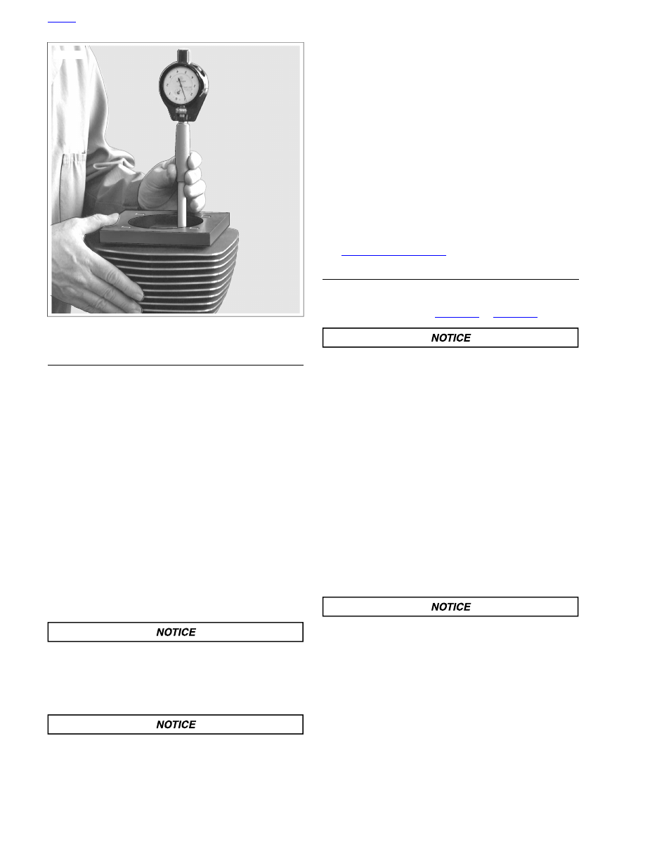
sm02532

Figure 3-61. Measure for Out-of-Round and Taper

DEGLAZING CYLINDER

NOTE

Deglazing removes wear patterns, minor scuff marks and
scratches without enlarging the bore diameter.

1.

Lightly swab the cylinder bore with a cloth dipped in clean
engine oil.

2.

Obtain a 240 grit flexible ball-type deglazing tool with a
bristle tip or finishing stone arrangement able to produce
a 60 degree crosshatch pattern.

3.

Install the deglazing tool in a slow-speed drill. The speed
at which the tool rotates determines the speed at which it
must be stroked up and down the bore to produce the
desired crosshatch pattern.

4.

Starting at the bottom of the cylinder, move the deglazing
tool up and down the entire length of the cylinder bore for
10 to 12 complete strokes.

5.

Stop to examine the cylinder bore and/or take measure-
ments. A precise 60 degree crosshatch pattern in the
piston travel area is the most important.

The angular crosshatch pattern ensures an even flow of
oil onto the cylinder walls and promotes longer cylinder,
piston and ring life. An incorrect cross hatch pattern will
result in insufficient oil retention and possible piston
seizure and/or high oil consumption. (00536c)

Failure to remove all abrasive particles may result in pre-
mature cylinder, piston and ring wear and engine failure.
(00537c)

6.

Thoroughly wash the cylinder bore with liquid dishwashing
soap and hot water to remove all abrasive particles and
residual grit. Continue cleaning until a clean cloth shows
no evidence of dirt or debris.

7.

Hot rinse the cylinder and dry with moisture free com-
pressed air. Immediately apply a thin film of clean engine
oil to a clean white paper towel and thoroughly wipe the
inside of the cylinder to prevent the cylinder bore from
rusting.

NOTE

After wiping the cylinder with a clean, oiled paper towel, the
towel will be dark with contamination. Repeat this process
using a new lightly oiled paper towel each time until the towel
remains white. The cylinder is now clean.

8.

With the cylinder at room temperature, check the piston
clearance in the cylinder in which the piston will run. See

3.22 PISTON, Inspection

.

BORING AND HONING CYLINDER

1.

Bore cylinder with gaskets and torque plates attached.
Bore the cylinder to 0.003 in. (0.08 mm) under the desired
finished size. Refer to

Table 3-38

or

Table 3-39

.

An incorrect crosshatch pattern or too fine a hone will
result in insufficient oil retention and possible piston
seizure and/or high oil consumption. (00538c)

2.

Honing the cylinder:

a.

Hone the cylinder to its finished size using a 280 grit
rigid hone followed by a 240 grit flexible ball hone.

b.

Honing must be done with the torque plates attached.

c.

All honing must be done from the bottom (crankcase)
end of the cylinder. Work for a 60 degree crosshatch
pattern.

3.

Stop frequently to examine the cylinder bore and/or take
measurements.

Remember,

a

precise

60

degree

crosshatch pattern in the piston travel area is important.

NOTE

Example: A 0.005 in. (0.13 mm) oversize piston for a Twin Cam
96 will have the proper running clearance with a cylinder bore
size of 3.7550-3.7555 in. (95.377-95.390 mm).

Failure to remove all abrasive particles may result in pre-
mature cylinder, piston and ring wear and engine failure.
(00537c)

4.

Thoroughly wash the cylinder bore with liquid dishwashing
soap and hot water to remove all abrasive particles and
residual grit. Continue cleaning until a clean cloth shows
no evidence of dirt or debris.

5.

Hot rinse the cylinder and dry with moisture free com-
pressed air. Immediately apply a thin film of clean engine
oil to a clean white paper towel and thoroughly wipe the
inside of the cylinder to prevent the cylinder bore from
rusting.

HOME

3-54 2013 Softail Service: Engine

NOTE

After wiping the cylinder with a clean, oiled paper towel, the
towel will be dark with contamination. Repeat this process
using a new lightly oiled paper towel each time until the towel
remains white. The cylinder is now clean.

6.

With the cylinder at room temperature, check the piston
clearance in the cylinder in which the piston will run. See

3.22 PISTON, Inspection

.

Table 3-38. Oversize Pistons/Cylinder Bores, Twin Cam 96

CYLINDER BORE FINISHED SIZE

PISTON

MM

IN

MM

IN

SIZE

95.250-95.263

3.7500-3.7505

N/A

N/A

Standard

95.377-95.390

3.7550-3.7555

0.13

0.005

Oversize

95.504-95.517

3.7600-3.7605

0.25

0.010

Table 3-39. Oversize Pistons and Cylinder Bores, Twin Cam 103

CYLINDER BORE FINISHED SIZE

PISTON

MAXIMUM

MINIMUM

SIZE

TYPE

3.8755 in (98.438 mm)

3.8750 in (98.425 mm)

STD

Standard

3.8855 in (98.692 mm)

3.8850 in (98.679 mm)

0.010 in (0.25 mm)

Oversize

HOME

2013 Softail Service: Engine 3-55

3.22

PISTON

DISASSEMBLY

TOOL NAME

PART NUMBER

PISTON RING EXPANDER

SNAP-ON PRS8

Piston Rings

Wear safety glasses or goggles when removing or
installing compression rings. Compression rings can slip
from the pliers and could be propelled with enough force
to cause serious eye injury. (00469c)

1.

See

Figure 3-62

. Carefully remove top (7) and second (6)

compression rings using the proper PISTON RING
EXPANDER (Part No. Snap-on PRS8).

2.

Using your fingers, remove top and bottom oil rails (4)
from the third ring groove. Remove the oil rail expansion
ring (5).

3.

Discard the piston rings.

1

3

6

1

2

4

4

7

5

sm02508

1. Circlip
2. Piston pin
3. Piston
4. Oil rail
5. Expansion ring
6. Second compression ring
7. Top compression ring

Figure 3-62. Piston Assembly

CLEANING

1.

Remove all carbon and combustion deposits by soaking
the pistons in hot water with dishwashing liquid or a
cleaner specifically designed to remove carbon and will
not corrode aluminum. Follow the manufacturer's instruc-
tions when using these cleaners.

NOTE

Do not sand blast or glass bead blast pistons. Bead blasting
rounds off ring lands. This will result in oil contamination leading
to accelerated wear.

Compressed air can pierce the skin and flying debris from
compressed air could cause serious eye injury. Wear
safety glasses when working with compressed air. Never
use your hand to check for air leaks or to determine air
flow rates. (00061a)

2.

Thoroughly rinse the pistons. Dry parts with moisture free
compressed air.

3.

Clean the oil drain holes leading from the oil control ring
groove to the underside of the piston crown. Run a small
bristle brush through the passageways. Do not damage
or enlarge the holes. Do not use a wire brush.

4.

Verify that all other oil holes are clean and open.

NOTE

Avoid scratching the sides of the piston ring grooves.

5.

Thoroughly clean the three piston ring grooves of all
carbon deposits. A portion of a compression ring properly
ground to a sharp chisel-like edge works well for this pur-
pose.

6.

Using Magnaflux Dye Penetrant, inspect the piston for
surface cracks. Particularly examine the area around the
pin bores, ring lands and oil drain holes beneath the piston
crown. If no cracks are found, thoroughly wash piston to
remove traces of dye.

INSPECTION

1.

See

Figure 3-63

Check piston pin. Pin must slide without

binding.

a.

Insert a lightly oiled good piston pin into the piston
pin bore to feel for the proper interference fit. The pin
should slide in and out without binding, but also
without pivoting or rocking.

b.

Measure pin and pin bore diameters to determine
running clearance. Replace piston and/or pin if
clearance exceeds 0.0008 in. (0.02 mm).

NOTE

Pistons with superficial wear marks, minor scratching or mild
scoring may continue to be used.

HOME

3-56 2013 Softail Service: Engine

2.

Carefully inspect the pistons for damage or excessive
wear.

a.

Discard pistons with cracked, worn or bent ring lands.

b.

Check the piston skirt for cracks, gouges, deep
scratches or heavy scoring.

c.

Check the piston heads for evidence of burning,
etching or melting.

d.

Look for marks or imprints caused by contact with
valves.

3.

Run your index finger around the edge of the piston crown
to feel for dings, nicks or burrs. Lightly file the edge of the
crown to remove any defects.

NOTE

Worn ring grooves result in high oil consumption and blow-by
of exhaust gases. Blow-by of exhaust gases contaminates the
engine oil supply with acids and leaves sludge in the crankcase.
It also reduces engine efficiency by weakening the combustion
seal necessary for efficient transfer of energy to the piston.

4.

See

Figure 3-64

. Measure piston ring side clearance.

a.

Insert the edge of a

new

ring into the piston ring

groove. Insert a feeler gauge between the upper sur-
face of the ring and the ring land.

b.

Since the grooves wear unevenly, repeat this check
at several locations around the piston groove circum-
ference.

c.

Discard the piston if the side clearance of either
compression ring exceeds 0.0045 in. (0.11 mm).

d.

Discard the piston if the oil control ring side clearance
exceeds 0.010 in. (0.25 mm).

NOTES

Check the piston clearance in the cylinder in which the
piston will run. The cylinder must be deglazed and have
torque plates installed when measuring bore.

This inspection is very heat sensitive. Both the piston and
cylinder must be at room temperature before proceeding.
Do not check piston running clearance immediately after
honing or deglazing cylinder. Even holding the piston for
too long can cause measurements to vary by as much as
0.0002 in. (0.0051 mm).

See upper frame of

Figure 3-65

Piston measurement is

taken on the bare aluminum for greatest accuracy. The
coating has an oval-shaped opening (1) on each side of
the piston for proper micrometer placement.

See lower frame of

Figure 3-65

. The oval openings are

too small for a standard flat anvil micrometer which would
result in measuring errors. Use a blade or ball anvil style
micrometer to measure piston.

5.

See

Figure 3-65

Measure running clearance of pistons

as follows:

a.

Measure the piston skirt at the bare aluminum open-
ings (1) in the coating. Transfer that measurement to
dial bore gauge.

b.

Using a grease pencil, mark the top, middle and
bottom of the piston ring travel zone in the cylinder
bore. Measure at markings in cylinder parallel and
perpendicular to crankshaft.

c.

Replace piston and/or cylinder if running clearance
exceeds 0.003 in. (0.076 mm).

sm02534

Figure 3-63. Piston Pin Clearance

sm02535

Figure 3-64. Measure Piston Ring Side Clearance

HOME

2013 Softail Service: Engine 3-57

1

3

2

sm02509

1. Bare aluminum opening
2. 4-5 in micrometer
3. Spherical ball anvil adapters

Figure 3-65. Measuring Running Clearance of Piston

ASSEMBLY

TOOL NAME

PART NUMBER

PISTON RING EXPANDER

SNAP-ON PRS8

Checking Piston Ring Gap

NOTES

Always use new piston rings. Piston rings take a definite
set and must not be reused if the engine has been oper-
ated. Always deglaze (or hone) the cylinder before
installing new rings.

Insufficient ring gap may cause the ends to abut at oper-
ating temperatures. This will result in ring breakage, cyl-
inder scuffing and/or piston seizure.

Excessive ring gap results in high oil consumption and
blow-by of exhaust gases. Blow-by contaminates the oil
supply and leaves sludge in the crankcase. It also reduces
engine efficiency by weakening the combustion seal
necessary for efficient transfer of energy to the piston.

1.

See

Figure 3-66

. Check ring end gap of each ring before

placing on the piston. Insert the

new

ring into the cylinder

and square it in the bore using the top of the piston.

Measure the ring end gap with a feeler gauge. Refer to

Table 3-40

.

NOTE

Ring end gap dimensions also apply to oversize rings. Replace
ring if end gap exceeds specification. If end gap is under spe-
cification, filing is permissible.

Compressed air can pierce the skin and flying debris from
compressed air could cause serious eye injury. Wear
safety glasses when working with compressed air. Never
use your hand to check for air leaks or to determine air
flow rates. (00061a)

2.

Use compressed air to remove any dirt or dust that may
have settled in the oil drain holes and piston ring grooves.

Table 3-40. Piston Ring End Gap

PISTON

MM

IN

0.305-0.559

0.012-0.022

Top compression

Twin
Cam 103

0.381-0.635

0.015-0.025

2nd compression

0.254-1.270

0.010-0.050

Oil control ring

sm02536

Figure 3-66. Measuring Ring Gap

Installing Piston Rings

1.

See

Figure 3-67

. Apply clean engine oil to three piston

ring grooves.

2.

Install expansion ring (4) into third ring groove.

3.

Spiral bottom oil rail (5) into space below expansion ring
(4). Position gap 90 degrees from the gap in the expansion
ring.

4.

Spiral top oil rail (3) into space above expansion ring (4).
Position gap 180 degrees from the gap in the bottom oil
rail.

HOME

3-58 2013 Softail Service: Engine

Wear safety glasses or goggles when removing or
installing compression rings. Compression rings can slip
from the pliers and could be propelled with enough force
to cause serious eye injury. (00469c)

NOTES

Use the proper piston ring spreader to prevent excessive
ring twist and expansion. Over expansion may cause the
ring to crack. Damaged or distorted rings result in blow-
by of exhaust gases. This will result in increased oil con-
sumption and lower service life on valves and other com-
ponents.

Installing the second compression ring upside down will
cause oil to be scraped up into the combustion chamber.
This will result in excessive oil consumption and lower
service life on valves and other components.

5.

Using PISTON RING EXPANDER (Part No. Snap-on
PRS8), carefully install the second compression ring. Make
sure the dot (punch mark) near the ring gap faces the
piston crown. Rotate the ring so the gap is 180 degrees
from the gap in the oil expansion ring.

6.

Install the top compression ring. Make sure the dot (punch
mark) near the ring gap faces the piston crown. Rotate
the ring so the gap is 180 degrees from the gap in the
second compression ring.

7.

Rotate the three piston rings using the palms of both
hands. The rings must rotate freely without sticking.

8.

See

Figure 3-68

. Verify the ring gaps are still properly

staggered.

2

1

3

4

5

sm02537

1. Top compression ring
2. Second compression ring
3. Top oil rail
4. Expansion ring
5. Bottom oil rail

Figure 3-67. Piston Rings

3

4

2

1

1

2

4

3

5

5

6

7

sm02182

1. Expander ring
2. Bottom oil rail
3. Top oil rail
4. Second compression ring
5. Top compression ring
6. Front
7. Rear

Figure 3-68. Piston Ring Gap Alignment

HOME

2013 Softail Service: Engine 3-59

3.23

TOP END OVERHAUL: ASSEMBLY

GENERAL

NOTES

It is assumed that each step performed on one cylinder is
automatically repeated on the other.

Do not use 2006 and earlier connecting rods with 2007
and later pistons. 2007 and later pistons have a tapered
wrist pin boss. The wrist pin portion of the 2007 and later
connecting rod is tapered to match the boss on the piston.

This section provides a sequential process for top end
assembly after a complete disassembly. If only a partial disas-
sembly was performed, start where necessary and continue
to the end of the section.

PISTON

TOOL NAME

PART NUMBER

PISTON PIN CIRCLIP
REMOVER/INSTALLER

HD-42317-A

1.

Slide approximately 6.0 in. (152 mm) of plastic tubing,
rubber hose or conduit over each cylinder stud, if removed.
Use material with I.D. of 0.5 in. (12.7 mm) to protect cyl-
inder studs and piston from damage.

2.

Apply SCREAMIN' EAGLE ASSEMBLY LUBE to piston
pin, piston bosses and upper connecting rod bore.

3.

Remove water pipe insulation from connecting rod shank.

4.

See

Figure 3-69

Place piston over rod end so that the

arrow stamped at the top of the piston points toward the
front of the engine.

5.

See

Figure 3-70

. Insert piston pin (1) through pin bore and

upper connecting rod bore. Push pin until it contacts circlip
installed in opposite pin boss. Verify that end gap (3) for
circlip is 180 degrees from opening (2).

6.

Place clean shop towels over the cylinder and lifter bores
to prevent the piston pin circlip from falling into the crank-
case. Verify that the circlip groove is clean and free of dirt
and grime.

sm02379

Figure 3-69. Piston Installation Arrow

2

3

1

sm02380

1. Piston pin
2. Circlip opening
3. End gap location

Figure 3-70. Pre-Installed Circlip

NOTE

Do not reuse piston pin circlips. The circlips could weaken
during removal causing them to break or dislodge during engine
operation, a condition that will result in engine damage.

HOME

3-60 2013 Softail Service: Engine

7.

Install

new

piston pin circlip with the PISTON PIN CIRCLIP

REMOVER/INSTALLER (Part No. HD-42317-A).

a.

See

Figure 3-71

. Slide circlip down nose of tool until

it contacts claw. Lightly squeeze handles of tool to
capture circlip in claw.

b.

Releasing pressure on handles, rotate circlip so that
the end gap is centered at top of tool and then
recapture in claw.

c.

Tilt the circlip forward until the end gap contacts nose
of tool.

d.

See

Figure 3-72

. Insert the tool (1) into the piston pin

bore until claw is aligned with slot (2) in piston.

e.

Firmly push the tool into the piston pin bore until it
bottoms. Release handles and remove tool.

f.

Inspect the circlip to verify that it is fully seated in the
groove.

sm02339

Figure 3-71. Aligning Circlip

1

2

3

sm02341

1. Piston pin circlip remover/installer
2. Slot
3. Cylinder deck dowel (O-ring not shown)

Figure 3-72. Pin Circlip Installation

CYLINDER

TOOL NAME

PART NUMBER

PISTON SUPPORT PLATE

HD-42322

THREADED CYLINDERS

HD-95952-1

CONNECTING ROD CLAMPING TOOL

HD-95952-33C

PISTON RING COMPRESSOR

HD-96333-51F

1.

See

Figure 3-72

Apply a very thin film of clean engine oil

to

new

O-rings for both lower cylinder deck dowels. Install

and verify that O-ring is properly seated in groove.

2.

See

Figure 3-73

Apply a very thin film of clean engine oil

to

new

O-ring seal for the bottom of the cylinder liner.

Install

new

O-ring seal.

NOTE

Excessive lubrication of cylinder sleeve O-ring seal will result
in oil weepage between cylinder and crankcase as engine is
run. This condition may be incorrectly diagnosed as an oil leak.

3.

See

Figure 3-74

. Verify that the piston ring end gaps are

staggered. Rotate each ring to position the gap 90 to 180
degrees from the gap in the ring above it. Locate the top
piston ring (5) gap towards the intake port.

4.

Apply clean engine oil to piston, piston rings and cylinder
bore.

5.

Remove protective covers from cylinder studs. Rotate
engine until piston is at top dead center. If necessary, see

3.16 TOP END OVERHAUL: DISASSEMBLY, Rocker Arm
Support Plate

for different methods of engine rotation.

6.

See

Figure 3-75

Install the PISTON SUPPORT PLATE

(Part No. HD-42322).

a.

Slide both adjustable knobs (2) on support plate (1)
down away from forked end. Tighten knobs when
contact is made with flats at end of slots.

b.

With the forked end of the tool pointing towards the
center of the engine and the adjustable knobs facing
downward, capture shank of connecting rod in fork.
Lay tool on cylinder deck so that adjustable knobs
contact wall of cylinder bore.

c.

Rotate engine until piston skirt is centered and firmly
seated on top of support plate.

HOME

2013 Softail Service: Engine 3-61

7.

See

Figure 3-76

. Install cylinder using PISTON RING

COMPRESSOR (Part No. HD-96333-51F).

a.

Fit tabs on pliers (1) into slots of ring compressor band
(2). The arrow stamped on the band indicates the
side that faces up, so disregard the word "bottom".

b.

Place band around piston. Press the lever on the right
side of the pliers to open the jaws for band expansion.

c.

Orient tool so that the top of the band is positioned
between the top compression ring and the piston
crown.

d.

Tightly squeeze handles of tool to compress piston
rings. The ratcheting action of the tool allows release
of the handles after the rings are compressed.

e.

With the indent in the cooling fins facing the right side
of the engine, gently slide cylinder over the cylinder
studs and the piston crown resting it on the top of the
ring compressor band.

f.

Place the palms of both hands at the top of the cyl-
inder. Push down on the cylinder with a sharp, quick
motion to pass the piston ring area.

g.

Rotate the engine slightly to raise piston off support
plate. Remove pliers from band and then remove
band from around shank of connecting rod. Remove
piston support plate.

8.

Remove shop towels from around the crankcase bore and
keep out any dirt or debris.

9.

Carefully set the cylinder over the two dowel pins in the
cylinder deck. Push down on the cylinder until it is fully
seated in the crankcase bore.

10. See

Figure 3-77

. Install THREADED CYLINDERS (Part

No. HD-95952-1) from CONNECTING ROD CLAMPING
TOOL (Part No. HD-95952-33C) onto cylinder studs with
the knurled side down.

sm02342

Figure 3-73. O-ring Seal For Cylinder

3

4

2

1

1

2

4

3

5

5

6

7

sm02182

1. Expander spring
2. Bottom oil rail
3. Top oil rail
4. Second compression ring
5. Top compression ring
6. Front
7. Rear

Figure 3-74. Piston Ring Alignment

HOME

3-62 2013 Softail Service: Engine

1

2

3

sm02343

1. Support plate
2. Knobs
3. Screw

Figure 3-75. Piston Support Plate

1

2

2

1

sm02344

1. Pliers
2. Compressor band

Figure 3-76. Piston Ring Compressor

sm02345

Figure 3-77. Install Threaded Cylinders to Studs

CYLINDER HEAD

TOOL NAME

PART NUMBER

SNAP-ON TORQUE ANGLE GAUGE

TA360

TORQUE VALUE

FASTENER

13.6-16.3 Nm

120-144

in-lbs

Cylinder head bolts, 1st torque

20.3-23.0 Nm

15-17 ft-lbs

Cylinder head bolts, 2nd
torque

90 degrees

90 degrees

Cylinder head bolts, final
torque

13.6-19.0 Nm

120-168

in-lbs

Rocker housing bolts

NOTES

"Front" or "Rear" is cast into the top of the cylinder head
to verify proper installation. The indent in the cooling fins
always faces the right side of the engine.

Lower the cylinder head at an angle that closely approxim-
ates the angle of the crankcase to avoid damage to
machined surfaces or the dowel pins.

Thoroughly clean and lubricate the threads of the cylinder
head bolts before installation. Friction caused by dirt and
grime will result in a false torque indication.

1.

See

Figure 3-78

With the part number facing up, place

the head gasket over the two dowel pins in the upper
flange of the cylinder.

2.

Slide cylinder head squarely over the two cylinder flange
dowel pins.

3.

Lightly coat the threads and bottom face of the cylinder
head bolts in clean engine oil. Wipe off any excess oil.

4.

See

Figure 3-79

. Loosely install the cylinder head bolts.

Place two short bolts on the left side of the engine and
two long bolts on the right.

HOME

2013 Softail Service: Engine 3-63

2

1

sm02295

1. Cylinder
2. Dowel pin

Figure 3-78. Cylinder Dowel Pins

3

1

2

4

4

2

1

3

sm02392a

1. Short bolt
2. Short bolt
3. Long bolt
4. Long bolt

Figure 3-79. Cylinder Head Bolt Torque Sequence (Top:

Front Cylinder Head, Bottom: Rear Cylinder Head)

NOTE

Improperly tightened cylinder head bolts may result in gasket
leaks, stud failure or distortion of the cylinder and/or cylinder
head.

5.

Tighten the cylinder head bolts:

a.

See

Figure 3-79

. Following sequence shown, turn

each cylinder head bolt until finger tight.

b.

Following the same sequence, tighten the cylinder
head bolts to 120-144

in-lbs

(13.6-16.3 Nm).

c.

Continuing the same sequence, tighten each bolt to
15-17 ft-lbs (20.3-23.0 Nm).

HOME

3-64 2013 Softail Service: Engine

6.

See

Figure 3-80

Final-tighten each bolt an additional 90

degrees (90 degrees) in the same sequence. For best
results, use SNAP-ON TORQUE ANGLE GAUGE (Part
No. TA360).

a.

If using a grease pencil, mark a straight line on the
cylinder head bolt continuing the line over onto the
cylinder head.

b.

Use the marks as a guide to achieve the 90 degrees.

sm02395

Figure 3-80. Final Tightening for Cylinder Head Bolts

NOTES

Although the gasket bolt holes appear to be in alignment,
the rocker housing gasket can be installed upside down.
An upside down gasket will result in an open breather
channel. This will cause a major oil leak when the vehicle
is started, possibly resulting in engine and/or property
damage.

On front cylinder head, install side of gasket marked "front"
facing up. On rear cylinder head, install side of gasket
marked "rear" facing up.

7.

See

Figure 3-81

. Install a

new

rocker housing gasket on

the cylinder head. Verify that the rocker housing gasket
covers the breather channel.

2

1

sm02350

2.

1.

INCORRECT: Breather channel exposed

CORRECT: Breather channel covered

Figure 3-81. Install Rocker Housing Gasket (Rear Cylinder Shown)

HOME

2013 Softail Service: Engine 3-65

8.

See

Figure 3-83

. Install rocker housing.

a.

With the indent (1) facing forward, place the rocker
housing into position aligning the holes in the housing
with those in the gasket.

b.

See

Figure 3-82

. Apply a drop of LOCTITE 243

MEDIUM

STRENGTH

THREADLOCKER

AND

SEALANT (blue) to threads of six rocker housing
bolts.

c.

Loosely install the rocker housing bolts.

d.

Place two long bolts on the left side of the engine and
four intermediate bolts in the interior.

e.

Tighten the bolts in the sequence shown to 120-168

in-lbs

(13.6-19.0 Nm).

NOTES

If the engine was left in the chassis for service, final tighten
the rear left rocker housing bolt (rear cylinder) using a
torque wrench with a 1/4 in. drive.

Since many O-rings are similar in size and appearance,
always use new O-rings. Use of the wrong O-ring will
result in either oil leakage or low oil pressure. Keep them
packaged until use to avoid confusion.

9.

See

Figure 3-83

Apply a very thin film of clean engine oil

to

new

baffle hole O-ring (2). Install

new

O-ring in groove

around breather baffle hole in rocker housing.

NOTE

Do not confuse breather baffle hole O-ring (Part No. 11270,
large inner diameter) with the top pushrod O-ring (Part No.
11293, small inner diameter).

4

6

2

1

5

3

1

5

3

4

6

2

sm02389

1. Short bolt, 1.25 in. (31.8 mm)
2. Long bolt, 1.75 in. (44.5 mm)
3. Long bolt, 1.75 in. (44.5 mm)
4. Short bolt, 1.25 in. (31.8 mm)
5. Short bolt, 1.25 in. (31.8 mm)
6. Short bolt, 1.25 in. (31.8 mm)

Figure 3-82. Rocker Housing Torque Sequence and Bolt

Size

HOME

3-66 2013 Softail Service: Engine

2

1

sm02394

1. Indent
2. Breather baffle hole O-ring

Figure 3-83. Rocker Housing Alignment

PUSHRODS, LIFTERS AND COVERS

TORQUE VALUE

FASTENER

10.2-13.6 Nm

90-120

in-lbs

Lifter cover screws

1.

Remove any labels used on the hydraulic lifters. Apply a
thin film of SCREAMIN' EAGLE ASSEMBLY LUBE to outer
surface of each lifter. Pour a small amount onto each cam
lobe.

2.

Install lifters in the crankcase bores with the oil hole on
the inboard side and the flats on the lifters facing forward
and rearward. To avoid damage, do not drop lifters onto
cam lobes.

3.

See

Figure 3-84

. Place the anti-rotation pin (4) on the

machined flat between the blocks cast into the crankcase.

4.

Install

new

O-rings in the lifter cover bores and the cylinder

head pushrod cover bores.

NOTE

During cover installation, verify that the anti-rotation pin (4) is
held in place by the ribs (3) cast into the inboard side of the
lifter cover. Movement or loss of the pin can result in lifter
rotation causing engine damage.

5.

Install the lifter cover (1) and

new

gasket (2). Install four

socket head screws. Tighten the lifter cover screws to 90-
120

in-lbs

(10.2-13.6 Nm) in a crosswise pattern.

6.

Install pushrod covers.

a.

Assemble pushrod covers with

new

O-rings.

b.

Hand compress the pushrod cover assembly and fit
the pushrod cover into the lifter cover bore.

c.

Extending the assembly, fit the pushrod cover into
the cylinder head bore.

d.

Do not install the spring cap retainers at this time.

NOTE

To install spring cap retainers, see

3.23 TOP END OVERHAUL:

ASSEMBLY, Rocker Arm Support Plate

.

7.

Apply a small amount of SCREAMIN' EAGLE ASSEMBLY
LUBE to the ends of each pushrod.

8.

See

Figure 3-85

. Install the pushrods. If installing original

parts, install them in their original locations and orientation.
Be sure to remove any tags that may have been used for
identification.

4

2

1

3

sm02346

1. Cover
2. Gasket
3. Ribs on cover
4. Anti-rotation pin

Figure 3-84. Installing Lifters

HOME

2013 Softail Service: Engine 3-67

2

4

1

3

sm02181

1. Front cylinder exhaust pushrod
2. Front cylinder intake pushrod
3. Rear cylinder intake pushrod
4. Rear cylinder exhaust pushrod

Figure 3-85. Pushrod Locations

ROCKER ARM SUPPORT PLATE

TOOL NAME

PART NUMBER

SNAP-ON "DOG BONE" TORQUE
ADAPTER

FRDH161

TORQUE VALUE

FASTENER

24.4-29.8 Nm

18-22 ft-lbs

Rocker arm support plate bolts

NOTE

Installing the rocker arms and rotating the crankshaft with the
valve train loaded can result in bent pushrods, damaged
bushings or a warped support plate.

1.

Rotate the crankshaft to position both lifters of the cylinder
being serviced on the base circle (or lowest position) of
the cam lobe.

2.

See

Figure 3-86

. Place the rocker arm support plate

assembly into the rocker housing and loosely install four
rocker arm support plate bolts with flat washers.

NOTE

Engine in chassis: Final tighten rocker arm support plate bolt
on rear left side of rear cylinder using 3/8 in. drive torque
wrench with 1/2 in. flank drive SNAP-ON "DOG BONE"
TORQUE ADAPTER (Part No. FRDH161) or equivalent.

3.

Tighten rocker arm support plate bolts.

a.

Following the sequence shown, alternately tighten
each of the four rocker arm support plate bolts 1/4
turn at a time until snug.

b.

Following the same sequence, tighten the bolts to 18-
22 ft-lbs (24.4-29.8 Nm).

4.

Verify that both pushrods spin freely.

NOTE

Always service each cylinder separately. After the first cylinder
is serviced rotate the crankshaft to find the base circle on the
second cam.

5.

Repeat steps on remaining cylinder.

3

2

1

4

2

3

4

1

sm02386a

Figure 3-86. Rocker Arm Support Screw Sequence

6.

Complete installation of the pushrod covers.

a.

Verify that the O-ring ends of the upper and lower
pushrod covers fit snugly into the cylinder head and
lifter cover bores.

b.

Insert the upper edge of spring cap retainer into the
cylinder head bore leaving the bottom edge free.

c.

Insert blade of small screwdriver between bottom
edge of spring cap retainer and top of spring cap.

NOTE

For best results, verify that screwdriver, spring cap and
spring cap retainer are free of grease and oil.

d.

See

Figure 3-87

Press spring cap down with tip of

screwdriver and slide bottom edge of retainer towards
tip of screwdriver.

e.

Verify that spring cap retainer seats tightly against
upper pushrod cover.

HOME

3-68 2013 Softail Service: Engine

sm02347

Figure 3-87. Install Spring Cap Retainers

BREATHER AND ROCKER COVER

TOOL NAME

PART NUMBER

"DOG BONE" TORQUE ADAPTER

SNAP-ON FRDH141

TORQUE VALUE

FASTENER

13.6-17.6 Nm

120-156

in-lbs

Breather assembly screws

20.3-24.4 Nm

15-18 ft-lbs

Rocker cover screws

NOTE

For

breather

assembly

service

procedures,

see

3.17 BREATHER ASSEMBLY

.

1.

To secure breather assembly, tighten two screws to 120-
156

in-lbs

(13.6-17.6 Nm).

NOTE

If the engine is in the chassis, final tighten the three rocker
cover bolts on the left side of the rear cylinder using a 3/8 in.
drive torque wrench with a 7/16 in. flank drive "DOG BONE"
TORQUE ADAPTER (Part No. Snap-on FRDH141). Failure to
properly use this combination will over-tighten the bolts causing
distortion of the rocker cover.

2.

Apply a drop of LOCTITE 243 MEDIUM STRENGTH
THREADLOCKER AND SEALANT (blue) to threads of
rocker cover screws.

3.

See

Figure 3-88

Install rocker cover and a

new

rocker

cover gasket. Tighten screws following the sequence
shown to 15-18 ft-lbs (20.3-24.4 Nm).

4.

Complete motorcycle assembly.

a.

If engine was left in the chassis for service, see

3.13 ASSEMBLING MOTORCYCLE AFTER SER-
VICE

.

b.

If

engine

was

removed

for

service,

see

3.15 INSTALLING ENGINE IN CHASSIS

.

6

2

4

3

1

5

4

2

6

5

1

3

sm02326

1. Short bolt, 1.0 in. (25.4 mm)
2. Long bolt, 1.75 in. (44.5 mm)
3. Short bolt, 1.0 in. (25.4 mm)
4. Long bolt, 1.75 in. (44.5 mm)
5. Short bolt, 1.0 in. (25.4 mm)
6. Long bolt, 1.75 in. (44.5 mm)

Figure 3-88. Rocker Cover Bolts Torque Sequence

HOME

2013 Softail Service: Engine 3-69


Content      ..     19      20      21      22     ..