Harley Davidson Softail Delux FLSTN BIKE 2011-2015. Service Manual - page 19
 

  Главная      Harley Davidson     Harley Davidson Softail Delux FLSTN BIKE 2011-2015. Service Manual and Tool Catalog


Search            copyright infringement  


Content      ..     17      18      19      20     ..


Harley Davidson Softail Delux FLSTN BIKE 2011-2015. Service Manual - page 19


ENGINE REMOVED FROM CHASSIS

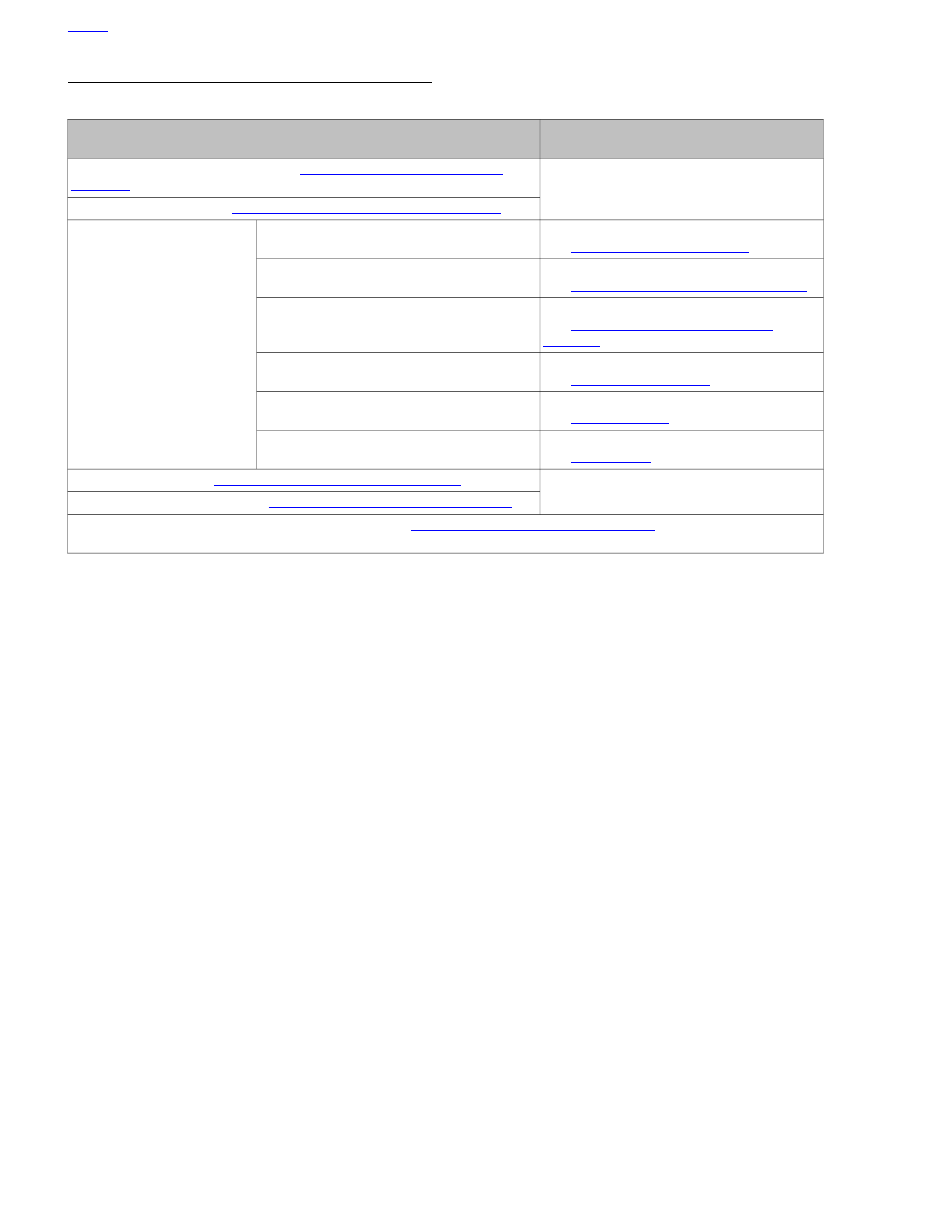
Table 3-33. Engine Removed From Chassis

COMPONENT REPAIR
PROCEDURE

SERVICE PROCEDURE

Remove engine from motorcycle. See

3.14 REMOVING ENGINE FROM

CHASSIS

.

Disassemble top end. See

3.16 TOP END OVERHAUL: DISASSEMBLY

.

Inspect and repair.

BREATHER ASSEMBLY

See

3.17 BREATHER ASSEMBLY

*.

Inspect and repair.

ROCKER ARM SUPPORT

See

3.18 ROCKER ARM SUPPORT PLATE

*.

Inspect and repair.

PUSHRODS, LIFTERS AND COVERS

See

3.19 PUSHRODS, LIFTERS AND

COVERS

*.

Inspect and repair.

CYLINDER HEAD

See

3.20 CYLINDER HEAD

*.

Inspect and repair.

CYLINDER

See

3.21 CYLINDER

*.

Inspect and repair.

PISTON

See

3.22 PISTON

.

Assemble top end. See

3.23 TOP END OVERHAUL: ASSEMBLY

.

Install engine in motorcycle. See

3.15 INSTALLING ENGINE IN CHASSIS

.

Note: * If no other work is to be done, you may advance to

3.23 TOP END OVERHAUL: ASSEMBLY

when this step is completed

during top end service.

HOME

3-22 2013 Softail Service: Engine

3.11

CAM COMPARTMENT SERVICE

ENGINE IN CHASSIS

Table 3-34. Engine In Chassis: Cam Compartment Service

COMPONENT REPAIR
PROCEDURES

SERVICE PROCEDURE

Remove parts to gain access to all components above cylinder deck. See

3.12 STRIPPING MOTORCYCLE FOR SERVICE

.

Dissassemble top end. See

3.16 TOP END OVERHAUL: DISASSEMBLY

.

Inspect and repair.

BREATHER ASSEMBLY.

See

3.17 BREATHER ASSEMBLY

.

Inspect and repair.

ROCKER ARM SUPPORT PLATE.

See

3.18 ROCKER ARM SUPPORT PLATE

.

Inspect and repair.

PUSHRODS, LIFTERS AND COVERS.

See

3.19 PUSHRODS, LIFTERS AND

COVERS

.

Disassemble bottom end. See

3.24 CAM COMPARTMENT AND COMPON-

ENTS

.

Inspect and repair.

COVER AND CAM SUPPORT PLATE

See

3.24 CAM COMPARTMENT AND COM-

PONENTS

*.

Inspect and repair.

OIL PUMP

See

3.25 OIL PUMP

.

Assemble bottom end. See

3.24 CAM COMPARTMENT AND COMPONENTS

.

Assemble motorcycle. See

3.13 ASSEMBLING MOTORCYCLE AFTER SER-

VICE

.

Note: * If no other work is to be done, you may advance to

3.29 CRANKCASE ASSEMBLY

when this step is completed during

bottom end service.

HOME

2013 Softail Service: Engine 3-23

ENGINE REMOVED FROM CHASSIS

Table 3-35. Engine Removed: Flywheel Compartment Service or Complete Engine Overhaul

COMPONENT REPAIR
PROCEDURES

SERVICE PROCEDURE

Remove engine from motorcycle. See

3.14 REMOVING ENGINE FROM CHASSIS

.

Disassemble top end. See

3.16 TOP END OVERHAUL: DISASSEMBLY

.

Inspect and repair.

BREATHER ASSEMBLY

See

3.17 BREATHER ASSEMBLY

.

Inspect and repair.

ROCKER ARM SUPPORT PLATE

See

3.18 ROCKER ARM SUPPORT PLATE

.

Inspect and repair.

PUSHRODS, LIFTERS AND COVERS

See

3.19 PUSHRODS, LIFTERS AND

COVERS

.

Inspect and repair.

CYLINDER HEAD

See

3.20 CYLINDER HEAD

.

Inspect and repair.

CYLINDER

See

3.21 CYLINDER

.

Inspect and repair.

PISTON

See

3.22 PISTON

.

Disassemble bottom end.

Inspect and repair.

COVER AND CAM SUPPORT PLATE

See

3.24 CAM COMPARTMENT AND COM-

PONENTS

.

Inspect crankcase and repair.

CRANKCASE

See

3.26 CRANKCASE DISASSEMBLY AND

REPAIR

.

Inspect and repair flywheel/connecting rod
assembly.
See

3.27 FLYWHEEL AND CONNECTING

RODS

.

Assemble bottom end. See

3.29 CRANKCASE ASSEMBLY

and

3.24 CAM COMPARTMENT AND COMPONENTS

.

Assemble top end. See

3.23 TOP END OVERHAUL: ASSEMBLY

.

Install engine in motorcycle. See

3.15 INSTALLING ENGINE IN CHASSIS

.

HOME

3-24 2013 Softail Service: Engine

3.12

STRIPPING MOTORCYCLE FOR SERVICE

PROCEDURE

NOTE

If performing top end service (or both cam compartment and
top end), follow all the steps listed. If servicing cam compart-
ment components only, perform steps 1 though 8.

1.

Position motorcycle on a suitable lift.

2.

Remove seat.

To prevent accidental vehicle start-up, which could cause
death or serious injury, disconnect negative (-) battery
cable before proceeding. (00048a)

3.

Disconnect negative battery cable.

4.

Drain engine oil. See

1.6 ENGINE OIL AND FILTER

.

5.

Remove right footboard.

6.

Remove exhaust system. See

4.17 EXHAUST SYSTEM

.

7.

Remove air cleaner cover and backplate. See

4.3 AIR

CLEANER ASSEMBLY

.

Stop the engine when refueling or servicing the fuel
system. Do not smoke or allow open flame or sparks near
gasoline. Gasoline is extremely flammable and highly
explosive, which could result in death or serious injury.
(00002a)

8.

Drain and remove fuel tank. See

4.6 FUEL TANK

.

9.

Loosen and remove throttle control cables, if equipped,
from induction module.

10. Remove spark plug cables from spark plugs. Remove

spark plugs to avoid damaging them.

11. Remove top engine mount as an assembly.

12. Remove induction module connectors and induction

module. See

4.11 INDUCTION MODULE

.

HOME

2013 Softail Service: Engine 3-25

3.13

ASSEMBLING MOTORCYCLE AFTER SERVICE

PROCEDURE

TORQUE VALUE

FASTENER

47.5-54.2 Nm

35-40 ft-lbs

Cylinder head bracket bolts

61.0-67.8 Nm

45-50 ft-lbs

Engine mounting bolt, upper

NOTE

If top end service was performed (or both cam compartment
and top end), follow all the steps listed. If only cam compart-
ment components were serviced, start with step 5.

1.

Install induction module. See

4.11 INDUCTION MODULE

.

2.

Install top engine bracket assembly to frame tab and cyl-
inder heads.

a.

Tighten two cylinder head bracket bolts to 35-40 ft-
lbs (47.5-54.2 Nm).

b.

Tighten the upper engine to frame mounting bolt to
45-50 ft-lbs (61.0-67.8 Nm).

3.

Install spark plugs to cylinder heads. Connect spark plug
cables to spark plugs. See

1.17 SPARK PLUGS

.

4.

Install throttle cables to induction module.

5.

Install fuel tank, fuel gauge connector, fuel tank crossover
tube and instrument console. See

4.6 FUEL TANK

.

6.

Fill fuel tank with fuel.

7.

Install backplate and air cleaner cover. See

4.3 AIR

CLEANER ASSEMBLY

.

8.

Install heat shields and exhaust. See

4.17 EXHAUST

SYSTEM

9.

Install right floorboard.

10. Fill engine oil to proper level. See

1.6 ENGINE OIL AND

FILTER

.

11. Connect negative battery cable.

After installing seat, pull upward on seat to be sure it is
locked in position. While riding, a loose seat can shift
causing loss of control, which could result in death or
serious injury. (00070b)

12. Install seat.

13. Remove motorcycle from lift.

HOME

3-26 2013 Softail Service: Engine

3.14

REMOVING ENGINE FROM CHASSIS

PROCEDURE

1.

Position motorcycle on a suitable lift.

2.

Remove seat.

Disconnect negative (-) battery cable first. If positive (+)
cable should contact ground with negative (-) cable con-
nected, the resulting sparks can cause a battery explosion,
which could result in death or serious injury. (00049a)

3.

Disconnect both battery cables, negative cable first.
Remove battery.

4.

Drain primary chaincase and oil tank. See

1.6 ENGINE

OIL AND FILTER

and

1.9 PRIMARY CHAINCASE LUB-

RICANT

.

Stop the engine when refueling or servicing the fuel
system. Do not smoke or allow open flame or sparks near
gasoline. Gasoline is extremely flammable and highly
explosive, which could result in death or serious injury.
(00002a)

5.

Drain fuel tank. Remove instrument panel and fuel tank.
See

4.6 FUEL TANK

.

6.

Remove left and right footboards.

7.

Remove voltage regulator bracket. See

7.23 VOLTAGE

REGULATOR

.

8.

Remove exhaust system. See

4.17 EXHAUST SYSTEM

.

9.

Remove belt guard.

10. Loosen rear axle. Loosen belt adjusters. Remove drive

belt from rear pulley. move rear wheel back to provide
access to electrical panel.

11. Remove electrical panel. See

7.3 ELECTRICAL PANEL

.

12. Remove oil tank. See

3.30 OIL TANK: ALL BUT FXSB

or

3.31 OIL TANK: FXSB

.

13. Remove starter. See

7.13 STARTER

.

14. Unplug the vehicle speed sensor (VSS).

15. Remove primary chaincase cover and primary chaincase.

See

5.5 PRIMARY CHAINCASE HOUSING

.

16. Remove upper and lower fasteners from seat post. Discon-

nect coil connector and remove the post with the coil
attached.

17. Position a jack with a wooden block under the engine.

Remove the shift arm.

18. Remove the bracket (right side) connecting the frame to

the transmission case.

19. Remove the four fasteners connecting the engine to the

transmission.

20. Note routing of clutch cable before removing. Disconnect

clutch cable from clutch lever. Unclip cable at left side
frame downtube and pull cable through chassis to right
side of motorcycle. Leave cable installed on transmission.

21. On California models, remove the three hoses from the

evaporative emissions canister.

22. Remove the pivot shaft. Disconnect neutral switch wires

and slide the transmission back and then out the right side.

23. Remove bolts from horn bracket and cylinder heads.

Remove bracket as an assembly. Disconnect horn wire.

24. Remove induction module connectors. Remove air cleaner

cover and backplate. See

4.3 AIR CLEANER ASSEMBLY

.

Disconnect throttle cables.

25. If equipped with ACRs, disconnect ACR connectors.

26. Detach oil pressure sending unit connector.

27. Remove two bolts on front engine mount. Lift engine out

from right side of frame.

HOME

2013 Softail Service: Engine 3-27

3.15

INSTALLING ENGINE IN CHASSIS

PROCEDURE

TORQUE VALUE

FASTENER

20.3 Nm

15 ft-lbs

Transmission mounting bolts,
1st torque

46.1-52.9 Nm

34-39 ft-lbs

Transmission mounting bolts,
final torque

122-149.1 Nm

90-110 ft-lbs

Pivot shaft nut

94.9-108.5

Nm

70-80 ft-lbs

Engine mounting bolts, front

40.7-47.5 Nm

30-35 ft-lbs

Engine/transmission bracket
bolts

47.5-54.2 Nm

35-40 ft-lbs

Cylinder head bracket bolts

61.0-67.8 Nm

45-50 ft-lbs

Engine mount bolt, top

27.1-33.9 Nm

20-25 ft-lbs

Engine mount bracket nuts,
top

1.

Using a suitable hoist, position engine in chassis from the
right side.

2.

Loosely install the front two mounting bolts and spacers
from the right side.

a.

The shorter top bolt has a spacer installed on the right
side between the frame and the engine.

b.

The longer lower bolt has a spacer on both sides.
Loosely install corresponding washers and nuts.

3.

Attach induction module connectors and horn wire.

3

3

2

1

sm07691

1. Nut (3)
2. Upper engine to frame mounting bolt with

washer

3. Cylinder head bracket bolt with washer (2)

Figure 3-15. Top Engine Mount

4.

See

Figure 3-15

Loosen nuts (1).

5.

Loosely install upper engine to frame mounting bolt with
washer (2). Loosely install both cylinder head bracket bolts
with washers (3).

6.

If equipped with ACRs, attach ACR connectors.

NOTE

Use new transmission mounting bolts when installing transmis-
sion case. Do not reuse old bolts.

7.

See

Figure 3-16

. Install transmission case from the right

side. Align all four transmission mounting holes verifying
that the two lower locating dowels engage their holes in
crankcase.

8.

Tighten the four transmission mounting bolts in a crosswise
pattern:

a.

Tighten finger-tight.

b.

Tighten to 15 ft-lbs (20.3 Nm).

c.

Tighten to 34-39 ft-lbs (46.1-52.9 Nm).

9.

Apply ANTI-SEIZE LUBRICANT to pivot shaft. From the
right side, install pivot shaft and spacers with spacer collars
facing transmission case.

10. Apply LOCTITE 262 HIGH STRENGTH THREADLOCKER

and SEALANT (red) to pivot shaft nut.

11. Install pivot shaft nut. tighten to 90-110 ft-lbs (122-149.1

Nm).

HOME

3-28 2013 Softail Service: Engine

12. Apply LOCTITE 262 HIGH STRENGTH THREADLOCKER

and SEALANT (red) to both front mounting bolts. Tighten
to 70-80 ft-lbs (94.9-108.5 Nm).

13. Install lower bracket (right side). Apply LOCTITE 262 HIGH

STRENGTH THREADLOCKER and SEALANT (red).
Tighten bracket bolts to 30-35 ft-lbs (40.7-47.5 Nm).

NOTE

Always tighten the top engine mount hardware in the order
listed below to alleviate stress on the engine mount.

14. Final tighten upper engine mount hardware in the order

below.

a.

Tighten two cylinder head bracket bolts to 35-40 ft-
lbs (47.5-54.2 Nm).

b.

Tighten the upper engine to frame mounting bolt to
45-50 ft-lbs (61.0-67.8 Nm).

c.

Tighten the upper bracket to lower bracket nuts to 20-
25 ft-lbs (27.1-33.9 Nm).

15. Attach throttle cables. Adjust throttle cables. Connect fuel

hose to fuel tank.

16. Install air cleaner backplate and cover. See

4.3 AIR

CLEANER ASSEMBLY

.

17. Install regulator bracket. See

7.23 VOLTAGE REGU-

LATOR

.

18. Move the panel into position and tighten the two upper

bolts. Verify that all wiring is in place and not twisted or
kinked.

4

2

1

3

sm02789

Figure 3-16. Transmission Case Hardware

19. Install rear electrical panel. See

7.3 ELECTRICAL PANEL

.

NOTE

Replace the gasket between the primary chaincase cover and
chaincase each time the cover is removed. Failure to replace
this gasket could cause primary chaincase leaks.

20. Install primary chaincase. Attach the clutch cable, adjust

the

clutch

and

fill

with

LUBRICANT.

Start

with

5.5 PRIMARY CHAINCASE HOUSING

and follow all

necessary steps.

21. Install the left foot peg or foot board.

22. Install the seat post. Connect the coil connector and the

neutral switch wires.

23. Connect VSS to transmission.

24. Install starter. See

7.13 STARTER

.

25. Install oil tank and connect all oil lines. See

3.30 OIL

TANK: ALL BUT FXSB

or

3.31 OIL TANK: FXSB

.

26. Install belt guard.

27. Tighten axle nut.

28. Install heat shields, exhaust and right foot peg. See

4.17 EXHAUST SYSTEM

.

29. Install instrument console, fuel tank, fuel gauge connector

and fuel tank crossover tube. See

4.6 FUEL TANK

.

Connect positive (+) battery cable first. If positive (+) cable
should contact ground with negative (-) cable connected,
the resulting sparks can cause a battery explosion, which
could result in death or serious injury. (00068a)

30. Install battery and connect battery cables, positive cable

first.

After installing seat, pull upward on seat to be sure it is
locked in position. While riding, a loose seat can shift
causing loss of control, which could result in death or
serious injury. (00070b)

31. Install seat.

32. Install

new

oil filter and fill oil tank to proper level. See

1.6 ENGINE OIL AND FILTER

.

33. Remove motorcycle from lift.

34. Verify vehicle alignment. See

2.10 VEHICLE ALIGNMENT

.

35. Check drive belt deflection and alignment. See

1.12 DRIVE

BELT AND SPROCKETS

.

36. Check rear brakes, clutch and throttle for proper operation.

37. Check oil level after running motorcycle on sidestand. See

1.6 ENGINE OIL AND FILTER

.

HOME

2013 Softail Service: Engine 3-29

3.16

TOP END OVERHAUL: DISASSEMBLY

GENERAL

It is assumed that each step performed on one cylinder is
automatically repeated on the other.

To perform a complete top end overhaul, follow all steps listed
in this section including inspection and repair procedures.

ROCKER COVERS

NOTE

Dirt caked on cooling fins and other areas can fall into crank-
case bore. It can also stick to subassemblies as parts are
removed. Abrasive particles can damage machined surfaces
or plug oil passageways. Clean parts before disassembly to
prevent component damage.

1.

Use low pressure spray to thoroughly clean exterior sur-
faces of engine prior to disassembly.

2.

See

Figure 3-18

. Following the sequence shown, altern-

ately loosen the six rocker cover bolts. Remove the rocker
cover bolts and their captive washers.

3.

Remove the rocker cover and gasket. Discard gasket.

3

2

1

sm02324

1. Internal hex
2. External hex
3. Lock patch

Figure 3-17. Rocker Cover Bolt (Rocker Housing Bolt

Similar)

6

2

4

3

1

5

4

2

6

5

1

3

sm02326

Figure 3-18. Rocker Cover Bolt Removal Sequence

ROCKER ARM SUPPORT PLATE

TOOL NAME

PART NUMBER

CRANKSHAFT ROTATING WRENCH

HD-48283

1.

See

Figure 3-19

Insert the blade of a small screwdriver

into cast loop (1) of spring cap retainer. While pushing
down on spring cap (2), rotate bottom of screwdriver
toward outboard side to remove. Repeat step on second
pushrod cover.

HOME

3-30 2013 Softail Service: Engine

1

2

sm02329

1. Cast loop
2. Spring cap

Figure 3-19. Removing Spring Cap Retainer

2.

Collapse upper and lower pushrod covers.

NOTE

Do not attempt to rotate the crankshaft by placing a socket on
the crankshaft or primary cam sprocket flange bolt.

3.

When removing the rocker arm support plate, both lifters
must be on the base circle (lowest position) of the cam.
Rotate the crankshaft using one of the methods presented
below.

a.

With primary cover installed:

Remove spark plugs.

With the rear wheel raised, place the transmission in
6th gear and rotate rear wheel backward until the
base circle is found.

b.

With primary cover removed:

Remove spark plugs.

Place the transmission in neutral. Rotate the compens-
ating sprocket shaft nut counterclockwise until the
base circle is found.

c.

See

Figure 3-20

.

With engine mounted in engine

stand:

Install CRANKSHAFT ROTATING WRENCH

(Part No. HD-48283) on sprocket shaft and rotate
counterclockwise until the base circle is found.

sm02377

Figure 3-20. Crankshaft Rotating Wrench

4.

Rotate engine until piston is at TDC of compression stroke.

NOTE

Breather baffle assembly is manufactured with gaskets
attached. Any time the breather is disassembled, the baffle
assembly must be replaced with a new assembly.

5.

See

Figure 3-21

Remove two bolts to release breather

assembly (arrow) and filter element from the rocker arm
support plate. For inspection and repair information, see

3.17 BREATHER ASSEMBLY

.

6.

Loosen the four rocker arm support plate bolts 1/4 turn at
a time in the sequence shown. Remove the rocker arm
support plate bolts with flat washers.

7.

Remove the rocker arm support plate assembly. For
inspection and repair information, see

3.18 ROCKER ARM

SUPPORT PLATE

.

8.

See

Figure 3-22

Remove and discard breather O-ring

from rocker housing.

NOTE

If the other cylinder also requires service, find the cam base
circle for that cylinder before disassembling.

3

2

1

4

2

3

4

1

sm02386a

Figure 3-21. Rocker Arm Support Screw Sequence

HOME

2013 Softail Service: Engine 3-31

sm02680

Figure 3-22. Breather Baffle Hole O-Ring

PUSHRODS, LIFTERS AND COVERS

NOTE

Tag all components for location, function and orientation
(top/bottom) as they are removed.

1.

See

Figure 3-23

. Remove the intake and exhaust pushrods

and pushrod covers:

a.

Remove pushrods

b.

Remove pushrod covers.

c.

Remove three O-rings from pushrod covers and dis-
card. If O-ring is missing from upper pushrod cover,
be sure to dislodge it from the cylinder head bore.

2.

See

Figure 3-24

. Remove lifter covers.

a.

Using a crosswise pattern, remove four screws (1).

b.

Remove the lifter cover (2) and gasket. Discard
gasket.

3.

Remove lifters:

a.

Remove the anti-rotation pin to free the hydraulic
lifters.

b.

Remove the lifters and place in clean plastic bags to
prevent contamination.

4.

For inspection and repair information, see

3.19 PUSH-

RODS, LIFTERS AND COVERS

.

2

4

1

3

sm02181

1. Front cylinder exhaust pushrod
2. Front cylinder intake pushrod
3. Rear cylinder intake pushrod
4. Rear cylinder exhaust pushrod

Figure 3-23. Pushrod Locations

1

2

sm02378

1. Screw with captive washer (4)
2. Lifter cover

Figure 3-24. Lifter Cover

CYLINDER HEAD

TOOL NAME

PART NUMBER

CYLINDER TORQUE PLATES

HD-42324-A

1.

See

Figure 3-25

. Following the sequence shown, loosen

the six rocker housing bolts. Remove rocker housing bolts.

2.

Remove rocker housing and gasket. Discard gasket.

NOTE

To prevent distortion of the cylinder head, cylinder and cylinder
studs, gradually loosen the cylinder head bolts in the specified
sequence.

HOME

3-32 2013 Softail Service: Engine

3.

See

Figure 3-26

. Remove cylinder head bolts:

a.

Alternately loosen cylinder head bolts 1/4 turn at a
time the sequence shown.

b.

Remove the cylinder head bolts.

4.

Remove cylinder head and head gasket.

NOTE

Save the cylinder head gasket (if salvageable) for use with the
CYLINDER TORQUE PLATES (Part No. HD-42324-A) when
measuring, boring or honing of the cylinder is required.

5.

For inspection and repair information, see

3.20 CYLINDER

HEAD

.

4

6

2

1

5

3

1

5

3

4

6

2

sm02389

Figure 3-25. Rocker Housing Bolts Removal Sequence

3

1

2

4

4

2

1

3

sm02392

Figure 3-26. 1/4 Turn Head Bolts in Sequence

CYLINDER

1.

Raise the cylinder just enough to place clean shop towels
under the piston. This will prevent any dirt or debris, such
as broken ring pieces, from falling into the crankcase bore.

NOTE

Do not bend the cylinder studs. Even a slight bend or nick can
cause a stress riser leading to stud failure.

2.

Carefully remove the cylinder. Exercise caution to avoid
bending the cylinder studs. As the piston becomes free of
the cylinder, hold it upright to prevent it from striking the
studs or dragging across the stud thread area.

3.

Mark cylinder FRONT or REAR as appropriate.

4.

Slide approximately 6.0 in. (152 mm) of plastic tubing,
rubber hose or conduit over each cylinder stud. Use
material with ID of 0.5 in. (12.7 mm) to protect cylinder
studs and piston from damage.

5.

See

Figure 3-27

. Remove O-ring seal (4) from the bottom

of the cylinder liner. Discard O-ring seal.

HOME

2013 Softail Service: Engine 3-33

6.

See

Figure 3-28

Remove O-ring from dowel pin (4) on

base of cylinder deck. Discard O-ring.

7.

For inspection and repair information, see

3.21 CYL-

INDER

.

1

4

3

2

sm02294

1. Dowel pin
2. Head gasket
3. Cylinder
4. O-ring seal

Figure 3-27. Cylinder Assembly

PISTON

TOOL NAME

PART NUMBER

PISTON PIN RETAINING RING
INSTALLER

HD-42317-A

PISTON PIN REMOVER

HD-42320-B

1.

Verify that clean shop towels are properly positioned over
the crankcase bore to prevent the piston pin circlip from
falling into the crankcase.

Wear safety glasses or goggles when removing or
installing piston pin retaining rings. Piston pin retaining
rings are compressed in the ring groove and can fly out
when removed from the groove, which could result in
serious eye injury. (00293a)

NOTE

It is not necessary to remove both piston pin circlips for piston
removal.

2.

See

Figure 3-28

. Using PISTON PIN RETAINING RING

INSTALLER (Part No. HD-42317-A), remove and discard
one piston pin circlip.

a.

Insert tool (1) into the piston pin bore. Position claw
on tool in slot of piston (2) (directly under circlip).

b.

Hold shop towel over piston pin bore in case circlip
flies out during removal. Squeeze handles of tool
together. Pull circlip from bore. Discard circlip.

1

2

3

4

sm02336

1. Piston pin circlip remover/installer
2. Piston
3. Protective material over cylinder studs
4. Cylinder deck dowel (O-ring not shown)

Figure 3-28. Piston Pin Circlip Removal

3.

See

Figure 3-29

. Remove the piston pin. If piston pin is

difficult to remove, use PISTON PIN REMOVER (Part
No. HD-42320-B).

a.

Remove acorn nut and spacer from rod end of tool.

b.

Slide rod end through piston pin. Install spacer and
acorn nut (1) on end of rod.

c.

Position rubber-coated tips (2) of tool on flat each
side of pin bore.

d.

Turn handle (3) clockwise to remove piston pin.

4.

Remove the piston. Hold the connecting rod upright to
prevent it from striking the crankcase.

5.

Place a 3.0 in. (76.2 mm) long piece of foam-type water
pipe insulation around connecting rod to prevent damage.
Use material with an I.D. of 1.0 in. (25.4 mm).

6.

Turn the piston over. Mark the pin boss with the letters
F(ront) or R(ear) to identify location.

7.

For inspection and repair information, see

3.22 PISTON

.

HOME

3-34 2013 Softail Service: Engine

8.

Complete engine repair:

a.

If performing a top end overhaul only, see

3.23 TOP

END OVERHAUL: ASSEMBLY

.

b.

If performing a complete engine overhaul, see

3.24 CAM COMPARTMENT AND COMPONENTS

and

3.26

CRANKCASE

DISASSEMBLY

AND

REPAIR

.

3

2

1

sm02334

1. Spacer and acorn nut
2. Rubber coated tip
3. Handle

Figure 3-29. Piston Pin Removal

HOME

2013 Softail Service: Engine 3-35

3.17

BREATHER ASSEMBLY

DISASSEMBLY

NOTE

See

Figure 3-30

Breather baffle assembly is manufactured

with gaskets attached. Replacement part is supplied with the
filter element (5) and umbrella valve (3). Any time the breather
is disassembled, the baffle assembly must be replaced with a
new assembly.

1.

Remove rocker cover. See

3.16 TOP END OVERHAUL:

DISASSEMBLY, Rocker Covers

.

2.

Remove two fasteners (1) and remove breather cover (2).

3.

Remove breather baffle (4). Discard breather baffle, filter
element (5) and umbrella valve (3).

CLEANING AND INSPECTION

Compressed air can pierce the skin and flying debris from
compressed air could cause serious eye injury. Wear
safety glasses when working with compressed air. Never
use your hand to check for air leaks or to determine air
flow rates. (00061a)

1.

Clean cover and screws in a non-volatile cleaning solution
or solvent. Dry parts with low pressure compressed air.

2.

Set a straightedge diagonally across the length of the
breather cover intersecting the opposite corners of the
gasket surface.

3.

Slide a feeler gauge beneath the straightedge to check
the breather cover flatness.

4.

Repeat the step checking the opposite diagonal.

5.

Replace the breather cover if warpage exceeds 0.005 in.
(0.13 mm).

ASSEMBLY

See

Figure 3-30

. Install breather assembly and rocker cover

using

new

baffle assembly. See

3.23 TOP END OVERHAUL:

ASSEMBLY, Breather and Rocker Cover

.

5

3

2

6

4

1

sm02429a

1. Fasteners (2)
2. Breather cover
3. Umbrella valve
4. Breather baffle
5. Filter element
6. Rocker arm support plate

Figure 3-30. Breather Assembly

HOME

3-36 2013 Softail Service: Engine

3.18

ROCKER ARM SUPPORT PLATE

DISASSEMBLY

1.

See

Figure 3-31

Remove four bolts and flat washers (1)

from the rocker arm support plate (5).

2.

Remove the rocker arm shafts (4) so that the notched
ends exit the rocker arm support plate (5) first. Use a
hammer and brass drift if necessary. Mark the shafts so
that they are installed in their original locations at time of
assembly.

3.

Remove the rocker arms. Mark the rocker arms to indicate
location.

CLEANING AND INSPECTION

Inspection

Compressed air can pierce the skin and flying debris from
compressed air could cause serious eye injury. Wear
safety glasses when working with compressed air. Never
use your hand to check for air leaks or to determine air
flow rates. (00061a)

1.

Clean all parts in a non-volatile cleaning solution or
solvent. Dry parts with low pressure compressed air.

2.

See

Figure 3-31

. Check rocker arms (3) for uneven wear

or pitting where contact is made with the valve stem tips.
Check for concave wear where rocker arms contact the
pushrod ends. Replace rocker arm if excessive wear is
found.

3.

Verify that oil holes in rocker arms and rocker arm support
plate (5) are clean and open.

4.

Inspect rocker arm shafts (4) for scratches, burrs, scoring
or excessive wear. Replace as necessary.

6

5

1

2

3

4

sm02298

1. Bolt with flat washer
2. Rocker arm bushings
3. Rocker arm
4. Rocker arm shaft
5. Rocker arm support plate
6. Notch

Figure 3-31. Rocker Arm Assembly

Rocker Shaft Fit

1.

See

Figure 3-32

Measure the inside diameter of the rocker

arm support plate bore.

2.

See

Figure 3-33

Measure the outside diameter of the

rocker arm shaft where it fits in the bore.

3.

Repeat the measurement on opposite side of support plate
and shaft. Replace shaft or support plate if clearance
equals or exceeds 0.0035 in. (0.089 mm).

sm02431

Figure 3-32. Checking Support Plate Bore

HOME

2013 Softail Service: Engine 3-37


Content      ..     17      18      19      20     ..