Harley Davidson Softail Delux FLSTN BIKE 2011-2015. Service Manual - page 14
 

  Главная      Harley Davidson     Harley Davidson Softail Delux FLSTN BIKE 2011-2015. Service Manual and Tool Catalog


Search            copyright infringement  


Content      ..     12      13      14      15     ..


Harley Davidson Softail Delux FLSTN BIKE 2011-2015. Service Manual - page 14


6.

While holding pressure with the brake lever or pedal:

a.

Open bleeder valve about 3/4 turn.

b.

Close bleeder valve as soon as the lever or pedal has
moved full range of travel.

c.

Allow brake lever or pedal to return slowly to its
released position.

7.

Repeat steps until all air bubbles are purged and a solid
column of fluid is observed in the bleeder tube.

8.

Tighten bleeder valve to specification. Refer to

Table 2-16

.

Install bleeder valve cap.

NOTE

Dual caliper brake system: Repeat steps to bleed the second
brake line and caliper.

9.

Check and fill reservoir to specified level.

10. Refer to

Table 2-16

. Verify gasket and sealing surfaces

are free of debris. Install master cylinder reservoir cover
as follows:

a.

Front master cylinder reservoir:

Orient the cover

with the vent holes facing the rear. Install cover
screws. Tighten to specification.

b.

Rear master cylinder reservoir:

Install cover screws.

Tighten to specification.

11.

ABS equipped models:

Connect DIGITAL TECHNICIAN

II (Part No. HD-48650) and perform "ABS Service" pro-
cedure.

12. Verify stop lamp operation.

After repairing the brake system, test brakes at low speed.
If brakes are not operating properly, testing at high speeds
can cause loss of control, which could result in death or
serious injury. (00289a)

13. Test ride motorcycle. Repeat the bleeding procedure if

brakes feel spongy.

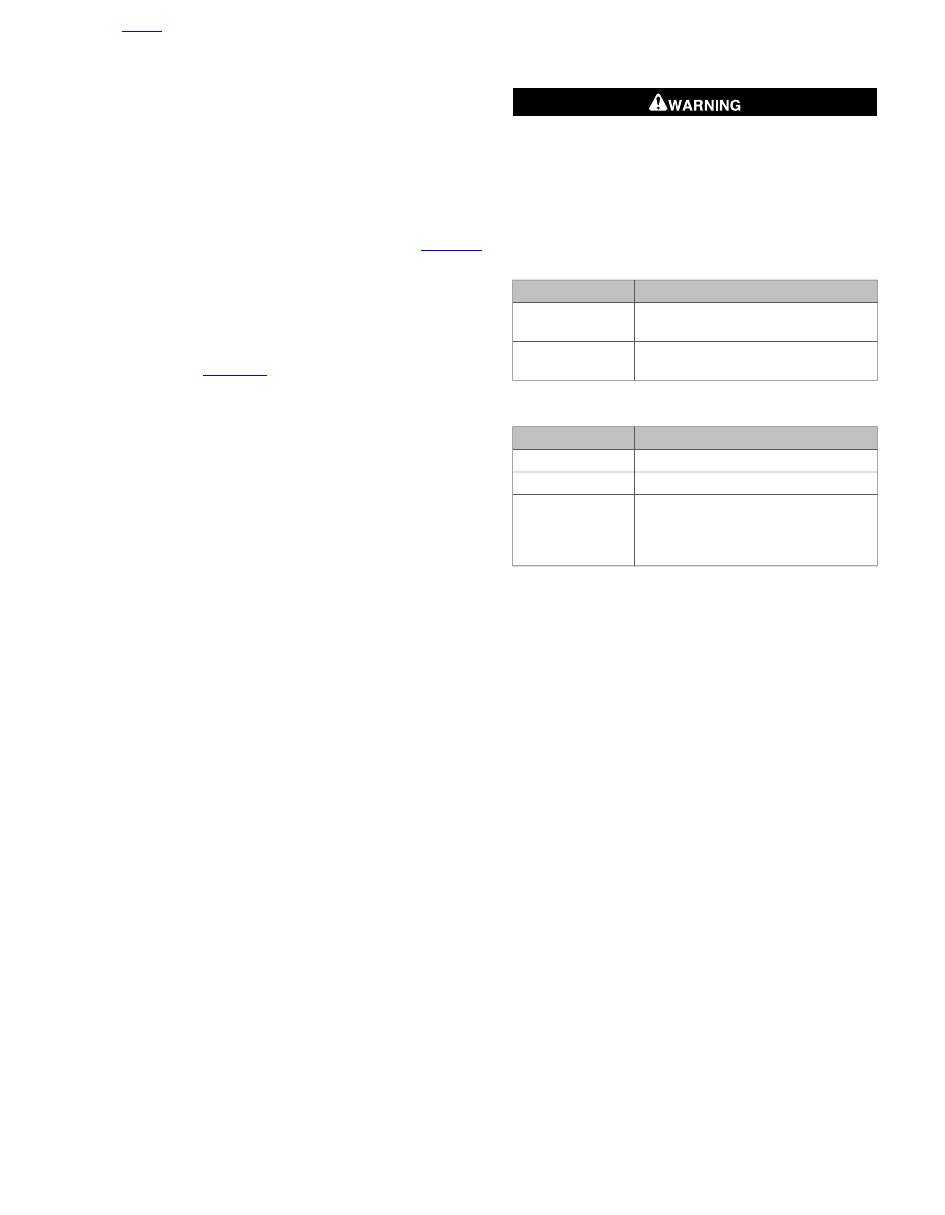
Table 2-15. Fluid Level

SPECIFICATION

ITEM

1/8-3/8 in (3.2-9.5 mm) below gasket
surface

Front reservoir

1/4-1/2 in (6.4-12.7 mm) below gasket
surface

Rear reservoir

Table 2-16. Torque Specifications

TORQUE

COMPONENT

80-100

in-lbs

(9.0-11.3 Nm)

Bleeder

12-15

in-lbs

(1.4-1.7 Nm)

Front cover

6-8

in-lbs

(0.7-0.9 Nm)

Rear cover: models
without remote
reservoir,non-ABS
models

HOME

2013 Softail Service: Chassis 2-57

2.16

FRONT FORK: TELESCOPIC

GENERAL

There are four varieties of hydraulic forks:

All FLSTC, FLSTF/B and FLSTN, FLS models use the
type shown in

Figure 2-71

.

All FXST models use the type shown in

Figure 2-72

.

All FXS models use the type shown in

Figure 2-73

.

All FXSB models use the type shown in

Figure 2-74

.

Use the following information to service the models listed
above.

REPLACING FORK OIL

TORQUE VALUE

FASTENER

5.9-8.9 Nm

52-78

in-lbs

Fork drain screw

81.3-95.0 Nm

60-70 ft-lbs

Fork tube cap

NOTES

At the specified fork oil change service interval, inspect
the front fork assembly. Look for oil leakage past the seals
and excessive wear on slider tubes. Disassemble, clean
and repair or replace components as necessary.

The FLSTC and FLSTF/B models have a preloaded fork
spring.

1.

Support the motorcycle so the front wheel is off the floor
and the forks are fully extended.

Wear safety glasses or goggles when servicing fork
assembly. Do not remove slider tube caps without relieving
spring preload or caps and springs can fly out, which could
result in death or serious injury. (00297a)

2.

See

Figure 2-69

. Remove the fork tube caps.

NOTE

FXSB models require the fork tubes be removed. Remove the
forks and drain the fork oil.

3.

Drain fork oil. See

Figure 2-70

Remove and discard the

drain screws and washers from each fork and drain the
fork oil.

4.

Install

new

drain screws and washers. Tighten drain

screws to 52-78

in-lbs

(5.9-8.9 Nm).

sm03093

Figure 2-69. Fork Tube Cap

5.

Fill the fork with Harley-Davidson TYPE E FORK OIL.
Refer to

Table 2-17

.

6.

Tighten fork tube caps to 60-70 ft-lbs (81.3-95.0 Nm).

Table 2-17. Type E Fork Oil Amounts

MM

IN

CC

OZ

MODEL

112.0

4.41

395

13.4

FLSTC, FLSTN,
FLS, FLSTF/B

170.0

6.69

370

12.5

FXST

132.0

5.20

398

13.5

FXS

85.0

3.35

790

26.7

FXSB

NOTE

Fork oil amounts can be measured two ways. Refer to

Table 2-17

.

Use oz./cc measurement if fork is left in frame.

Use in./mm measurement if fork is disassembled. In this
case, oil level is measured from top of fork tube, with
spring removed and fork fully compressed.

HOME

2-58 2013 Softail Service: Chassis

sm03921

Figure 2-70. Fork Drain Screw: (Left Side Shown)

REMOVAL

1.

Support the motorcycle so the front wheel is off the ground
and the forks are fully extended.

2.

Remove front wheel and brake caliper. See

2.4 FRONT

WHEEL

.

NOTE

Fuel tank crossover hose does not need to be disconnected.
Fuel tank can be slid back enough to remove required con-
nectors.

3.

All but FXST, FXS, FXSB:

a.

Slide fuel tank rearward. See

4.6 FUEL TANK

.

b.

Remove headlamp assembly. See

7.14 HEADLAMP

.

c.

Remove auxiliary lamps, if equipped. See

7.17 AUX-

ILIARY LAMPS: FLSTC, FLSTN

.

d.

See

Figure 2-71

. Remove front panel (51).

4.

Remove front fender. See

2.27 FRONT FENDER

.

5.

All but FXS, FXSB:

see

Figure 2-71

or

Figure 2-72

.

a.

Remove slider tube cap (1).

b.

Remove spacer (2) and oil seal (3).

6.

FXS, FXSB:

see

Figure 2-73

or

Figure 2-74

. Loosen fork

bracket pinch bolts (4,34) and pull each slider and tube
assembly from brackets.

7.

All but FXS, FXSB:

see

Figure 2-71

or

Figure 2-72

.

Loosen lower fork stem bracket pinch bolts (4) and pull
each slider and tube assembly from brackets.

DISASSEMBLY

Wear safety glasses or goggles when servicing fork
assembly. Do not remove slider tube caps without relieving
spring preload or caps and springs can fly out, which could
result in death or serious injury. (00297a)

1.

See

Figure 2-71

,

Figure 2-72

,

Figure 2-73

or

Figure 2-74

.

Remove the fork tube plug (5) and O-ring (6). Pull spring
(7) out of slider tube (8).

2.

All but FXSB:

Remove drain screw (9) and washer (10)

to drain the fork.

3.

FXST:

See

Figure 2-72

. Remove dust cover (23) and dust

shield (47).

4.

FXS:

See

Figure 2-73

Remove dust cover (23) and dust

shield (24).

5.

FXSB:

See

Figure 2-74

Remove case cover (23) and

dust seal (24).

6.

See

Figure 2-71

,

Figure 2-72

,

Figure 2-73

or

Figure 2-74

.

Compress retaining ring (11) and remove the clip from the
internal groove at the top of slider (12).

NOTE

Since there is little resistance to rotation when removing socket
screw (13), the job is done more easily with an air impact
wrench.

7.

Remove socket head screw (13) with washer (14) from
the bottom end of fork slider (12). This will free damper
tube (15) and fork slider tube (8) from slider.

8.

The upper slider tube bushing (16) is a slight interference
fit in slider (12). The upper bushing, seal spacer (17) and
slider oil seal (18) are removed together. Use the fork tube
and lower slider bushing (19) as a slide hammer. Pull the
fork tube in a quick continuous stroke. Continue this slide
hammer action until the components are freed.

9.

Push the damper tube (15) and damper tube spring (20)
free of slider tube (8) by inserting a small diameter rod
through the opening in the bottom of tube.

10. Remove lower stop (21) from the lower end of damper

tube (15).

11. Damper tube ring (22) can now be removed from the

grooves at the top end of damper tube (15). Do not remove
lower slider bushing (19) unless it requires replacement.
When replacing lower slider bushing (19), expand the

new

split bushing only enough to fit over slider tube (8). Slide
bushing into the bushing groove.

CLEANING AND INSPECTION

Thoroughly clean and inspect each part. If inspection shows
that any parts are bent, inoperative or damaged, those parts
should be replaced.

1.

Inspect damper tube rings (22) on damper tube (15) and
replace if worn excessively or damaged.

2.

Replace either of the springs (7 or 20) if damaged.

3.

Inspect small hole(s) in lower end of slider tube (8) and
be sure it is not obstructed.

4.

Be sure fork tube plug O-ring (6) is in good condition,
without irregularities, and that it provides proper sealing
when in place.

5.

Install

new

screw (9) and washer (10).

6.

Install

new

screw (13) and washer (14).

7.

Replace bent or damaged slider tube (8).

HOME

2013 Softail Service: Chassis 2-59

54

1

48

2

36

5

11

18

17

16

19

21

14

13

44

39

38

41

12

9

10

47

12

49

6

7

22

15

20

8

40

3

43

34

51

42

23

55

39

25

26

28

50

52

53

37

35

29

30

32

33

22

31

24

45

46

4

27

sm03216

39.

20.

1.

Lockwasher (2)

Damper tube spring (2)

Slider tube cap (2)

2.

40.

21.

Spacer (2)

Lockwasher (4)

Lower stop (2)

22.

3.

41.

Damper tube spring (2)

Oil seal (2)

Nut (2)

42.

23.

4.

Warning label

Clip nut

Bolt (2)

5.

43.

24.

Fork tube plug (2)

Fork stem retaining ring

Stem and bracket

25.

6.

44.

Fork stem cap

Fork tube plug O-ring (2)

Axle cap (2)

45.

26.

7.

Fork slider/tube asmb. right

Bolt

Spring (2)

8.

46.

27.

Slider tube (2)

Fork slider/tube asmb. left

Screw (2)

28.

9.

47.

Fork stem washer

Drain screw (2)

Reflector (2)

48.

29.

10.

Slider cover (2)

Upper bracket

Washer (2)

11.

49.

30.

Oil seal retaining ring (2)

Stud (4)

Upper dust shield

31.

12.

50.

Lower dust shield

Slider

Front panel bracket (2)

51.

32.

13.

Front panel

Roller bearing (2)

Screw (2)

14.

52.

33.

Washer (2)

Left rear back panel

Bearing cup (2)

34.

15.

53.

Adjusting nut

Damper tube (2)

Trim strip (2)

54.

35.

16.

Right rear back panel

Screw (4)

Upper slider tube bushing (2)

17.

55.

36.

Seal spacer

Bolt (2)

Screw (4)

37.

18.

Screw (4)

Slider oil seal (2)

19.

38.

Lower slider bushing

Washer (2)

Figure 2-71. Front Fork: FLSTC, FLSTF/B, FLSTN, FLS

HOME

2-60 2013 Softail Service: Chassis

26

43

42

29

27

25

28

34

30

32

33

32

31

35

45

46

23

9

37

36

10

47

11

18

17

19

12

40

13

14

41

38

8

20

15

7

5

2

3

22

16

21

6

1

39

4

44

24

sm03230

33.

17.

1.

Bearing race (2)

Seal spacer

Slider tube cap (2)

2.

34.

18.

Spacer (2)

Adjusting nut

Slider oil seal (2)

19.

3.

35.

Lower slider bushing

Oil seal (2)

Lockwasher (2)

36.

20.

4.

Washer (2)

Damper tube spring (2)

Bolt (2)

5.

37.

21.

Fork tube plug (2)

Lockwasher (2)

Lower stop (2)

22.

6.

38.

Damper tube ring (2)

Fork tube plug O-ring (2)

Nut (2)

39.

23.

7.

Pad (2)

Dust cover (2)

Spring (2)

8.

40.

24.

Slider tube (2)

Axle cap

Stem and bracket

25.

9.

41.

Fork stem cap

Drain screw (2)

Stud (2)

42.

26.

10.

Fork slider and tube assy. left

Fork stem nut

Washer (2)

11.

43.

27.

Oil seal retaining ring (2)

Fork slider and tube assy.
right

Screw (2)

28.

12.

Fork stem lockwasher

Slider

44.

13.

Reflector (2)

29.

Screw (2)

Upper bracket

30.

14.

45.

Upper dust shield

Washer (2)

Headlamp mounting plate

46.

31.

15.

Fork stem retaining ring

Lower dust shield

Damper tube (2)

16.

47.

32.

Upper slider tube bushing (2)

Dust shield (2)

Roller bearing (2)

Figure 2-72. Front Fork: FXST

HOME

2013 Softail Service: Chassis 2-61

1

2

3

4

8

32

28

30

31

30

29

19

27

10

5

6

7

33

34

22

15

20

21

35

36

26

25

13

14

9

23

17

18

11

24

16

12

sm07178

25.

13.

1.

Axle cap

Screw (2)

Fork stem nut

2.

26.

14.

Fork stem washer

Lockwasher (2)

Washer (2)

15.

3.

27.

Damper tube (2)

Upper bracket

Screw (2)

28.

16.

4.

Adjusting nut

Upper slider tube bushing (2)

Screw (2)

5.

29.

17.

Fork tube plug (2)

Upper dust shield

Seal spacer

18.

6.

30.

Slider oil seal (2)

Fork tube plug O-ring (2)

Roller bearing (2)

31.

19.

7.

Bearing race (2)

Lower slider bushing

Spring (2)

8.

32.

20.

Slider tube (2)

Lower dust shield

Damper tube spring (2)

21.

9.

33.

Lower stop (2)

Drain screw (2)

Stem and bracket

34.

22.

10.

Pinch bolt (2)

Damper tube ring

Washer (2)

11.

35.

23.

Oil seal retaining ring (2)

Fork slider and tube assy.
right

Dust cover (2)

24.

12.

Dust shield (2)

Slider

36. Fork slider and tube assy. left

Figure 2-73. Front Fork: FXS

HOME

2-62 2013 Softail Service: Chassis

33

1

3

4

2

28

29

30 31

31

30

32

34

23

24

11

18

17

16

9

10

7

15

22

20

21

36

35

27

26

25

13

14

12

19

5

6

8

37

sm07687a

27.

14.

1.

Screw (2)

Washer

Fork stem nut

2.

28.

15.

Washer

Adjusting nut

Damper tube

16.

3.

29.

Upper slider tube bushing (2)

Upper bracket

Upper dust shield

30.

17.

4.

Roller bearing (2)

Seal spacer

Upper pinch bolt (2)

5.

31.

18.

Slider tube plug

Bearing race (2)

Slider Oil seal (2)

19.

6.

32.

Lower slider tube bushing

O-ring

Lower dust shield

33.

20.

7.

Stem and bracket

Damper tube spring

Spring

8.

34.

21.

Slider tube (2)

Lower pinch bolt (2)

Lower stop

22.

9.

35.

Damper tube ring

Spring collar

Fork slider and tube
assembly, right

23.

10.

Case cover

Washer

36.

11.

Fork slider and tube
assembly, left

24.

Stopper ring

Dust seal

25.

12.

Axle cap

Slider

37.

13.

Fork stem cap

26.

Screw

Washer (2)

Figure 2-74. Front Forks: FXSB

HOME

2013 Softail Service: Chassis 2-63

ASSEMBLY

TOOL NAME

PART NUMBER

FORK SEAL INSTALLER

HD-34634

TORQUE VALUE

FASTENER

14.7-24.5 Nm

130-216

in-lbs

Fork damper tube screw, Front

1.

Install damper tube ring (22). Place damper tube spring
(20) on damper tube (15). Insert damper tube into slider
tube (8).

2.

Insert spring (7) into slider tube (8), tapered side toward
damper tube (15), and push bottom of damper tube
through the opening at the bottom end of the fork tube.
Place lower stop (21) over end of damper tube (15).

3.

Position slider tube (8) and damper tube (15) in slider (12).
Hold the assembly in place by exerting pressure on the
spring and install socket screw (13) with washer (14).

4.

Tighten screw (13) to 130-216

in-lbs

(14.7-24.5 Nm).

5.

Place upper slider tube bushing (16), seal spacer (17) and
a

new

slider oil seal (18) (in that order) over fork slider

(12). Be sure that the lettered side of the seal is facing
upward.

6.

Place FORK SEAL INSTALLER (Part No. HD-34634) over
fork slider (12). Seat upper slide tube bushing (16), seal
spacer (17), and slider oil seal (18) into the slider bore by
lightly tapping the components into place with the installa-
tion tool.

7.

Install oil seal retaining ring (11).

8.

FXST:

Install dust cover (23) and dust shield (47).

9.

FXS:

Install dust shield (24) and dust cover (23).

10.

FXSB:

Install case cover (23) and dust seal (24).

11. Fill forks with Harley-Davidson TYPE E FORK OIL. See

2.16 FRONT FORK: TELESCOPIC, Replacing Fork Oil

.

INSTALLATION

TORQUE VALUE

FASTENER

81.3-95.0 Nm

60-70 ft-lbs

Slider tube cap

74.6-81.3 Nm

55-60 ft-lbs

Fork stem pinch bolts, lower:
all but FXS/B

16.3-21.7 Nm

12-16 ft-lbs

Fork stem pinch bolts, upper:
FXS

16.3-21.7 Nm

12-16 ft-lbs

Fork stem pinch bolts, lower
final torque: FXS (tighten for
the second time after tight-
ening upper fork stem pinch
bolts. )

40.7-47.5 Nm

30-35 ft-lbs

Fork stem pinch bolts, upper
and lower: FXSB

1.

Insert both fork side assemblies up through the fork stem
and bracket (24) and upper bracket (29).

2.

FXS/B:

Adjust fork so that measurement (4) meets the

following specification.

a.

FXS:

0.533-0.583 in. (13.5-14.8 mm).

b.

FXSB:

0.35 in. (8.9 mm).

NOTE

Be sure one flat on each fork tube plug (5) faces toward the
inside of the fork.

3.

All but FXS/B:

Install

new

oil seal (3), spacer (2), and

slider tube cap (1). Tighten cap (1) to 60-70 ft-lbs (81.3-
95.0 Nm).

NOTE

FXS: After lower fork stem pinch bolts have been tightened to
specification, Tighten to specification a second time.

4.

Tighten fork stem bracket pinch bolt(s) (4) to the following:

a.

All but FXS/B:

55-60 ft-lbs (74.6-81.3 Nm).

b.

FXS upper:

12-16 ft-lbs (16.3-21.7 Nm).

c.

FXS lower:

12-16 ft-lbs (16.3-21.7 Nm).

d.

FXSB upper and lower:

30-35 ft-lbs (40.7-47.5 Nm).

5.

Install front fender. See

2.27 FRONT FENDER

.

6.

All but FXST, FXS, FXSB:

a.

See

Figure 2-71

Install front panel (51).

b.

Install auxiliary lamps, if equipped. See

7.17 AUXIL-

IARY LAMPS: FLSTC, FLSTN

.

c.

Install headlamp assembly. See

7.14 HEADLAMP

.

d.

Install fuel tank. See

4.6 FUEL TANK

.

7.

Install front wheel and brake caliper. See

2.4 FRONT

WHEEL

.

8.

Check steering head bearing adjustment if fork stem was
removed. See

1.18 STEERING HEAD BEARINGS

.

1

2

3

4

sm07168

1. Fork cap
2. Fork tube
3. Upper fork bracket
4. Measurement

Figure 2-75. Stem Protrusion: FXS

HOME

2-64 2013 Softail Service: Chassis

2.17

STEERING HEAD

REMOVAL

NOTE

If bearing races are removed, the bearings cannot be reused-
they must be replaced. See

2.17 STEERING HEAD, Disas-

sembly

, which follows.

FLSTC, FLSTF/B, FLSTN, FLS Models

1.

Remove fork shrouds.

2.

Remove the fork sides. See

2.16 FRONT FORK: TELE-

SCOPIC

.

3.

Remove the headlamp and headlamp bracket.

4.

See

Figure 2-76

. Remove the brake hose bracket from

the bottom of the fork stem and bracket (12).

5.

Remove the fork stem cap (1). Loosen pinch bolt (4) and
remove fork stem bolt (2). Remove washer (3) with the
handlebar and upper bracket (5) assembly.

6.

Remove the fork stem and bracket (12) from the steering
head. Remove the upper dust shield (6).

7.

Remove upper bearing (7).

6

7

1

3

2

4

5

8

9

10

11

12

sm03245

1. Fork stem cap
2. Fork stem bolt
3. Washer
4. Pinch bolt
5. Upper bracket
6. Upper dust shield
7. Upper bearing
8. Upper bearing race
9. Lower bearing race
10. Lower bearing
11. Lower dust shield
12. Fork stem and bracket

Figure 2-76. Steering Head: FLSTC, FLSTF/B, FLSTN, FLS

FXST Model

1.

Remove the fork sides. See

2.16 FRONT FORK: TELE-

SCOPIC

.

2.

Remove the headlamp and headlamp bracket.

3.

See

Figure 2-77

. Remove the brake hose bracket from

the bottom of the fork stem and bracket (13).

4.

Remove the fork stem cap (1). Remove the fork stem nut
(2) with the handlebar and upper bracket (4) as an
assembly.

5.

Remove the adjusting nut (6) and pull the fork stem and
bracket (13) out of the steering head.

6.

Remove the upper dust shield (7) and upper bearing (8)
from steering head.

6

1

3

5

2

4

7

8

9

10

11

12

13

sm03246

1. Fork stem cap
2. Fork stem nut
3. Lockwasher
4. Upper bracket
5. Pinch bolt
6. Adjusting nut
7. Upper dust shield
8. Upper bearing
9. Upper bearing race
10. Lower bearing race
11. Lower bearing
12. Lower dust shield
13. Fork stem and bracket

Figure 2-77. Steering Head: FXST

FXS, FXSB Models

1.

Remove the fork sides. See

2.16 FRONT FORK: TELE-

SCOPIC

.

HOME

2013 Softail Service: Chassis 2-65

2.

Remove the headlamp and headlamp bracket.

3.

See

Figure 2-78

or

Figure 2-79

Remove the brake hose

bracket from the bottom of the fork stem and bracket (12).

4.

Remove the fork sides. See

2.16 FRONT FORK: TELE-

SCOPIC

.

5.

Remove speedometer. See

7.26 SPEEDOMETER

.

6.

Remove the fork stem nut (1) with the handlebars and
upper bracket (4) as an assembly.

7.

Remove the adjusting nut (5) and pull the fork stem and
bracket out of the steering head.

8.

Remove the upper dust shield (6) and upper bearing (7)
from steering head.

5

1

3

2

4

6

7

8

9

10

11

12

13

sm07160

1. Fork stem nut
2. Washer
3. Upper bracket pinch bolt (2)
4. Upper bracket
5. Adjusting nut
6. Upper dust shield
7. Upper bearing
8. Upper bearing race
9. Lower bearing race
10. Lower bearing
11. Lower dust shield
12. Fork stem and bracket
13. Lower bracket pinch bolt (4)

Figure 2-78. Steering Head: FXS

5

1

3

2

4

6

7

8

9

10

11

12

13

sm07766

1. Fork stem nut
2. Washer
3. Upper bracket pinch bolt (2)
4. Upper bracket
5. Adjusting nut
6. Upper dust shield
7. Upper bearing
8. Upper bearing race
9. Lower bearing race
10. Lower bearing
11. Lower dust shield
12. Fork stem and bracket
13. Lower bracket pinch bolt (2)

Figure 2-79. Steering Head: FXSB

INSPECTION

All Models

1.

Check upper and lower bearing races in steering head. If
they are pitted or grooved, replace the bearings and races
in sets.

2.

Check the roughness of the bearings by turning them in
the race. Replace bearings if they do not turn freely and
smoothly.

HOME

2-66 2013 Softail Service: Chassis

DISASSEMBLY

TOOL NAME

PART NUMBER

UNIVERSAL DRIVER HANDLE

HD-33416

STEERING HEAD BEARING RACE
REMOVER

HD-39301A

Replace both bearing assemblies even if one assembly
appeares to be good. Mismatched bearings can lead to
excessive wear and premature replacement. (00532b)

Removing Lower Bearings From Fork Stem

1.

Chisel cage that holds rollers on bearing.

2.

Turn the fork stem upside down and heat the inner race.
The race will expand and fall off fork stem. Once the race
is removed, you will be able to remove the lower dust
shield.

Steering Head Bearing Race Removal

1.

See

Figure 2-80

. With the tapered side down, seat the

two-piece removal tool from the STEERING HEAD
BEARING RACE REMOVER (Part No. HD-39301A) on
the upper bearing race leaving a gap in the middle.

2.

Install the driver handle adapter on the UNIVERSAL
DRIVER HANDLE (Part No. HD-33416).

3.

Insert the driver at the bottom of the steering head tube,
and while holding the remover tool on the race, center the
collet in the gap. Tap the driver to remove the upper race.

4.

Reverse the tool and repeat the procedure to remove the
lower bearing race.

2

1

3

4

sm03249

Figure 2-80. Remove Upper and Lower Steering Head

Bearing Races

ASSEMBLY

TOOL NAME

PART NUMBER

STEERING HEAD BEARING RACE
INSTALLER

HD-39302

1.

Lubricate outside of the bearing races with engine oil.

2.

Install the

new

races using STEERING HEAD BEARING

RACE INSTALLER (Part No. HD-39302).

HOME

2013 Softail Service: Chassis 2-67

NOTE

Use care not to damage the new races' tapered surface. The
race should be firmly seated against the shoulder in the bore.

3.

Pack the

new

bearings with SPECIAL PURPOSE

GREASE.

4.

Install the lower dust shield on the fork stem. Press the
lower bearing into place. Use a sleeve that will contact
only the inner race of the

new

bearing.

INSTALLATION

TORQUE VALUE

FASTENER

10.8-13.6 Nm

96-120

in-lbs

Brake hose bracket bolt, front

33.9-40.7 Nm

25-30 ft-lbs

Fork stem upper bracket pinch
bolt: FLSTC, FLSTF/B,
FLSTN, FLS

10.8-13.6 Nm

96-120

in-lbs

Brake hose bracket bolt, front

94.9-108.4

Nm

70-80 ft-lbs

Fork stem nut: FXST

10.8-13.6 Nm

96-120

in-lbs

Brake hose bracket bolt, front

94.9-108.4

Nm

70-80 ft-lbs

Fork stem nut: FXS/FXSB

FLSTC, FLSTF/B, FLSTN, FLS Models

1.

See

Figure 2-76

. Insert the fork stem and bracket

assembly (12) (with lower dust shield and bearing) into
the frame steering head. Install the upper bearing (7) and
dust shield (6).

2.

Install the upper bracket (5), a

new

washer (3), and fork

stem bolt (2). Tighten the fork stem bolt until the bearings
have no noticeable shake. Fork stem must turn freely from
side to side.

3.

Fasten the brake hose bracket to bottom bracket using
original hardware. Tighten bolt to 96-120

in-lbs

(10.8-13.6

Nm).

4.

Install the headlamp assembly.

5.

Install the fork sides.

6.

Fill neck with SPECIAL PURPOSE GREASE through
grease fitting located in the steering head.

Properly adjust fork stem bearings. Improper adjustments
affect stability and handling, which could result in death
or serious injury. (00301a)

7.

Adjust fall-away. See

1.18 STEERING HEAD BEARINGS

.

8.

Apply ANTI-SEIZE LUBRICANT to upper bracket pinch
bolt (4). Tighten to 25-30 ft-lbs (33.9-40.7 Nm).

9.

Install the fork stem cap (1).

FXST Models

1.

See

Figure 2-77

Insert the fork stem bracket assembly

(13) (with lower dust shield and bearing) into the frame
steering head and install the upper bearing (8) and dust
shield (7). Secure with the adjusting nut (6).

2.

Install the upper bracket (4), a

new

lockwasher (3), and

fork stem nut (2). Be sure pin on lockwasher is engaged
in upper bracket hole.

3.

Fasten the brake hose bracket to bottom bracket using
original hardware. Tighten bolt to 96-120

in-lbs

(10.8-13.6

Nm).

4.

Install the headlamp assembly.

5.

Install the fork sides.

6.

Fill neck with SPECIAL PURPOSE GREASE through
grease fitting located in the steering head.

Properly adjust fork stem bearings. Improper adjustments
affect stability and handling, which could result in death
or serious injury. (00301a)

7.

Adjust fall-away. See

1.18 STEERING HEAD BEARINGS

.

8.

Tighten fork stem nut (2) to 70-80 ft-lbs (94.9-108.4 Nm).

9.

Install the fork stem cap (1).

FXS, FXSB Models

1.

See

Figure 2-78

and

Figure 2-79

. Insert the fork stem

bracket assembly (12) (with lower dust shield and bearing)
into the frame steering head and install the upper bearing
(7) and dust shield (6). Secure with the adjusting nut (5).

2.

Install the upper bracket (4), washer (2), and fork stem
nut (1).

3.

Fasten the brake hose bracket to bottom bracket using
original hardware. Tighten bolt to 96-120

in-lbs

(10.8-13.6

Nm).

4.

Install the headlamp assembly.

5.

Install the fork sides. See

2.16 FRONT FORK: TELE-

SCOPIC

.

6.

Fill neck with SPECIAL PURPOSE GREASE through
grease fitting located in the steering head.

Properly adjust fork stem bearings. Improper adjustments
affect stability and handling, which could result in death
or serious injury. (00301a)

7.

Adjust fall-away. See

1.18 STEERING HEAD BEARINGS

.

8.

Tighten fork stem nut (1) to 70-80 ft-lbs (94.9-108.4 Nm).

HOME

2-68 2013 Softail Service: Chassis

2.18

BELT GUARD AND DEBRIS DEFLECTOR

REMOVAL

Belt Guard

1.

Remove left saddlebag if present.

2.

See

Figure 2-81

. Remove acorn bolt (9) from tee nut (7).

3.

Remove acorn nut (4) to detach belt guard (5).

Debris Deflector

1.

Remove left saddlebag if present.

2.

Remove lower acorn bolt (3).

3.

Loosen, but do not remove, bolt (1) at front (slotted) portion
of deflector.

4.

Remove acorn nut (4). Lift debris deflector up and away
from frame.

INSTALLATION

Belt Guard

1.

See

Figure 2-81

. Place the belt guard (5) into position.

Tab for bolt and washer (6) must fit inboard of tab on
debris deflector (2).

2.

Install bolt and washer (6) through belt guard (5), debris
deflector (2) and rear fork. Install acorn nut (4) securely.

3.

Install acorn bolt (9) onto tee nut (7).

4.

Install left saddlebag if removed.

Debris Deflector

1.

Place debris deflector (2) into position. Slotted opening
on front of deflector slides over bolt (1). Do not tighten bolt
at this time.

2.

Install bolt and washer (6) through belt guard (5), debris
deflector (2) and rear fork. Install acorn nut (4) securely.

3.

Install lower acorn bolt (3) and tighten bolt (1) at front of
deflector.

4.

Install left saddlebag if removed.

9

5

4

3

2

1

8

7

6

sm03300

1. Bolt
2. Debris deflector
3. Acorn bolt
4. Acorn nut
5. Belt guard
6. Bolt and washer
7. Tee nut
8. Grommet
9. Acorn bolt (same as item 3)

Figure 2-81. Belt Guard/Debris Deflector

HOME

2013 Softail Service: Chassis 2-69

2.19

REAR SHOCK ABSORBERS

GENERAL

The rear shock absorbers are not repairable. If either shock
absorber becomes damaged, it must be replaced as an
assembly.

NOTE

See

1.22 SUSPENSION ADJUSTMENTS

for information

regarding setting up the suspension for carrying cargo.

REMOVAL

TOOL NAME

PART NUMBER

SNAP-ON-ADAPTER

SRES24

1.

Remove exhaust system. See

4.17 EXHAUST SYSTEM,

System: FLSTC, FXST, FXSB

or

4.17 EXHAUST

SYSTEM, System: FLSTN, FLSTF/B, FLS, FXS

.

2.

Remove HCU lower clamp fastener to allow for enough
clearance

to

remove

left

shock

absorber.

See

C.3 HYDRAULIC CONTROL UNIT (HCU), Rear Hydraulic
Control Unit (HCU)

.

3.

See

Figure 2-82

Remove jounce bumper (6) to raise rear

fork enough to remove right shock.

4.

Using a suitable lift, support motorcycle under frame until
rear tire is slightly off the ground.

5.

Remove bolt and washer (1) attaching shock to rear fork.

NOTE

SNAP-ON-ADAPTER (Part No. SRES24) is necessary to gain
access to shock bolt.

6.

Remove flange locknut (5) and washer with grommet (4)
at front of shock.

INSTALLATION

TOOL NAME

PART NUMBER

SNAP-ON-ADAPTER

SRES24

SNAP-ON TORQUE COMPUTER

SS-306G

TORQUE VALUE

FASTENER

164.0-184.4

Nm

121-136 ft-lbs

Shock bolt, rear

43.4-52.9 Nm

32-39 ft-lbs

Shock locknut, Rear

1.

See

Figure 2-82

Place washer with grommet (4) inside

frame. Install bushing (3) over stud end of shock. Insert
stud end through keyed frame tab and loosely install the
flange locknut (5).

2.

Coat shoulder of bolt (1) with ANTI-SEIZE LUBRICANT
and threads of bolt with LOCTITE 243 MEDIUM
STRENGTH THREADLOCKER AND SEALANT (blue).
Insert bolt and washer (1) through shock end. Pivot shock
absorber to align bolt with hole in rear fork.

NOTE

Softail shock absorber bolt torquing procedure requires the
use of a SNAP-ON-ADAPTER (Part No. SRES24). Since the
adapter lengthens the torque wrench, torque must be computed
with a SNAP-ON TORQUE COMPUTER (Part No. SS-306G).

3.

Tighten rear shock hardware.

a.

Tighten bolt and washer (1) at rear of shock to 121-
136 ft-lbs (164.0-184.4 Nm).

b.

Tighten the flange locknut (5) to 32-39 ft-lbs (43.4-
52.9 Nm).

4.

Adjust both shock absorbers equally. See

1.22 SUSPEN-

SION ADJUSTMENTS

.

5.

Install jounce bumper (6).

6.

Install HCU lower clamp fastener. See

C.3 HYDRAULIC

CONTROL UNIT (HCU), Rear Hydraulic Control Unit
(HCU)

.

7.

Install exhaust system. See

4.17 EXHAUST SYSTEM,

System: FLSTC, FXST, FXSB

or

4.17 EXHAUST

SYSTEM, System: FLSTN, FLSTF/B, FLS, FXS

.

HOME

2-70 2013 Softail Service: Chassis

1

2

3

4

5

6

sm03253a

1. Bolt and washer (2)
2. Rear shock (2)
3. Bushing (2)
4. Washer with grommet (2)
5. Flange locknut (2)
6. Jounce bumper

Figure 2-82. Rear Shocks

SHOCK DISPOSAL

1.

Disassemble the shock absorber.

NOTE

The damper reservoir contains nitrogen gas and oil under
pressure. Do not drill into the oil chamber.

2.

See

Figure 2-83

. Center punch the reservoir between the

weld and the reservoir can.

3.

Support the reservoir in a vise.

Do not expose shock absorber to heat source. Exposure
to heat source can build excessive gas pressure, which
could cause explosion and result in death or serious injury.
(00600b)

Use sharp drill bit to prevent excessive heat build up when
discharging.

4.

Install a 6/64-1/8 in. bit in a drill.

Discharging pressurized oil and gas can pierce skin and
cause flying debris, which could cause serious injury.
Wear safety glasses and gloves. (00601b)

5.

Drill at the punch mark retracting the drill as it penetrates
the shell.

6.

Allow the gas to escape.

7.

Dispose of the shock absorber.

HOME

2013 Softail Service: Chassis 2-71

sm06773

Figure 2-83. Center Punch/Drill Hole Location

HOME

2-72 2013 Softail Service: Chassis


Content      ..     12      13      14      15     ..