Harley Davidson 1986-2003 XL/XLH Sportster. Service Manual - page 41
 

  Главная      Harley Davidson     Harley Davidson 1986-2003 XL/XLH Sportster. Service Manual


Search            copyright infringement  


Content      ..     39      40      41      42     ..


Harley Davidson 1986-2003 XL/XLH Sportster. Service Manual - page 41


CAUTION

When installing the piston assembly, do not
allow the cup to turn inside out as it will be
damaged and allow brake fluid leaks within
the cylinder bore.

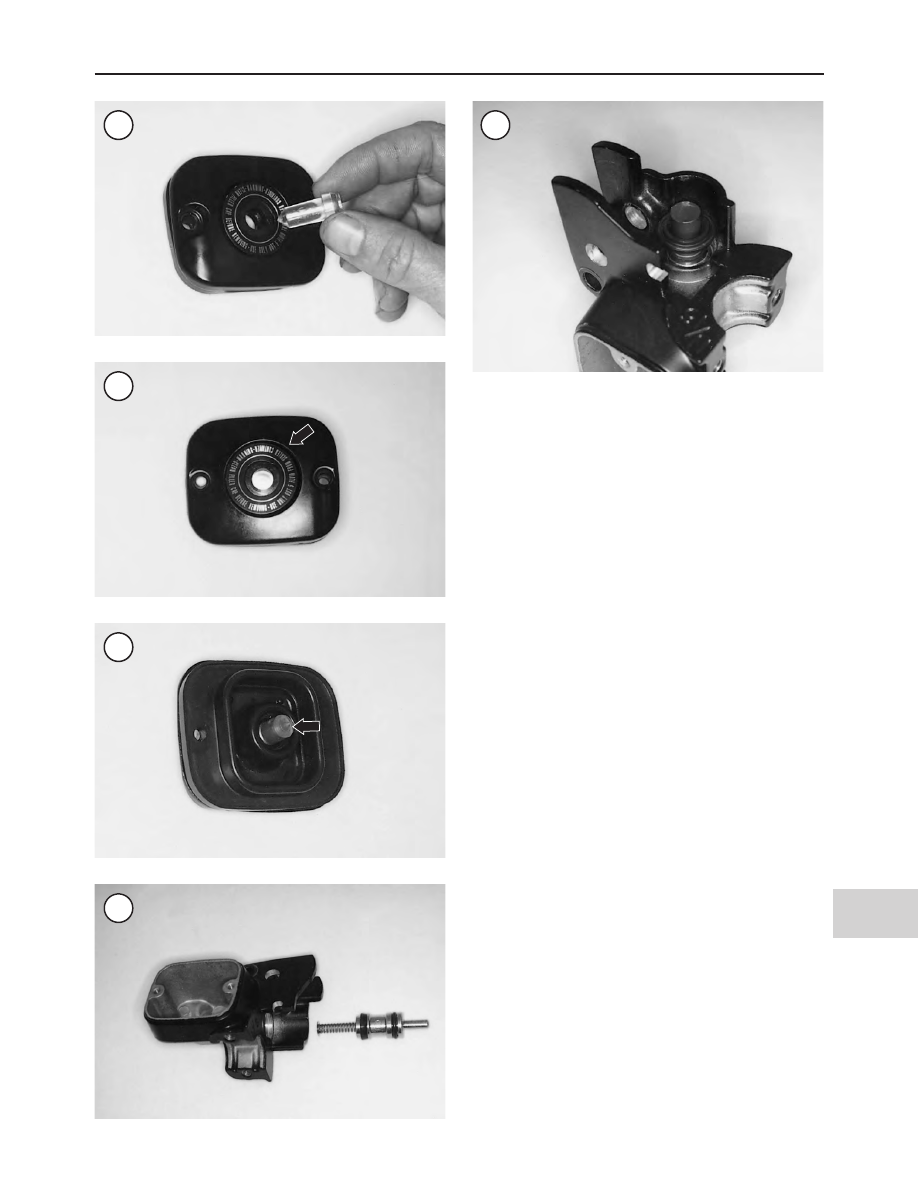
4. Install the spring and piston assembly into the cylinder
(Figure 88). Push them in until they bottom in the cylinder
(Figure 80).

5. Position the retainer with the flat side going on first, and
install the piston cap and retainer onto the piston end.

6. Push down on the piston cap (Figure 89). Hold it in
place and press the retainer down until it correctly seats in
the cylinder groove (A, Figure 79).

7. Make sure the bushing is in place in the hand lever pivot
area.

8. Install the hand lever (B, Figure 78) into the master cyl-
inder. Install the pivot pin and secure it with the snap ring.
Make sure the snap ring is correctly seated in the pivot pin
groove (A, Figure 78).

9. Apply the lever to make sure it pivots freely.

10. Install the master cylinder as described in this section.

REAR BRAKE PADS

(1986-EARLY 1987 MODELS)

There is no recommended mileage interval for changing

the brake pads. Pad wear depends on personal riding habits
and the condition of the brake system. Inspect the rear
brake pads for uneven wear, scoring, oil contamination or
other damage. Replace the brake pads if the pad thickness is
less than 0.062 in. (1.6 mm.).

Always replace the rear brake pads as a set.

Do not disconnect the brake hose from the caliper for

brake pad replacement. Only disconnect the brake hose if
removing the caliper.

Review

Brake Service

in this chapter.

BRAKES

557

16

85

86

87

88

89

Replacement

Refer to Figure 90.

1. Tie the end of the brake pedal to the frame so it cannot be
depressed. This prevents inadvertent application which
may cause the pistons to be pushed out the caliper.
2. Remove the two caliper body mounting screws (Figure
91
).
3. Pull the caliper body (5, Figure 90) away from the
mounting frame (3).
4. Remove the pad spring (Figure 92) from inside the caliper.
5. Secure the caliper body to the motorcycle. Do not allow
the caliper body to hang from the brake hose. Do not dis-
connect the brake line unless removing the caliper.

NOTE

If reusing the brake pads, mark each pad so it
can be reinstalled in its original position in
the caliper.

6. Slide the brake pads (Figure 93) off the frame.
7. Remove the upper and lower caliper pins. See Figure 94.
8. Check the abutment shims (Figure 95) in the caliper
frame. If they are worn or damaged, replace as follows:

a. Pry the abutment shims away from the caliper. See

Figure 96.

b. Remove all adhesive from the caliper surface where

the abutment shims are located.

c. Clean the abutment shim surfaces with rubbing alco-

hol.

558

CHAPTER SIXTEEN

90

REAR BRAKE CALIPER

(1986-EARLY 1987 MODELS)

1. Cap
2. Screw
3. Frame
4. Pad
5. Caliper body
6. Upper pin
7. Lower pin
8. Boot

9. Pad spring

10. Retaining ring
11. Boot
12. Piston
13. Seal
14. Bleed valve
15. Abutment shim
16. Plug

d. Apply silicone sealant to the abutment shim surfaces

on the caliper and install the abutment shims. Hold
the shims in position by installing the brake pads
(Figure 93) in the frame.

e. Allow the silicone sealant to dry thoroughly before

completing brake pad installation.

f. Make sure the brake pads slide freely in the frame.

9. Check the brake pads (Figure 97) for wear or damage.
Measure the brake pad thickness (Figure 98) and replace
them if they are worn to 0.062 in. (1.6 in.).

BRAKES

559

16

91

92

93

94

95

96

97

10. Check the brake caliper for brake fluid leaks. If brake
fluid has leaked from the caliper, rebuild it as described in
this section.

11. Inspect the brake disc as described in this chapter.

12. Inspect the pins (A, Figure 99) for wear or damage.
Check the boots (B, Figure 99) for tearing or deterioration.
Replace worn or damaged parts if necessary.

13. Inspect the pin bushings (Figure 100) in the frame for
wear or damage. Replace the frame assembly if the bush-
ings are worn or damaged.

14. Install the boots onto the pin bushings. Then install the
pin bushings in the frame. Insert the pin with the nylon
sleeve into the top frame bushing (Figure 94). Fit the boots
so they seat on the boss around the bushing holes.

CAUTION

If the boots are not seated properly, dirt can
enter and cause rapid pin and bushing
wear.

15. Turn the pins so the flats on the sides of the pins face as
shown in Figure 101.

CAUTION

Do not allow the master cylinder to overflow.
Brake fluid back flows to the reservoir as the
pistons are pushed back into their bores. Be-
cause brake fluid damages most surfaces, im-
mediately wash spilled brake fluid off
surfaces it contacts. Use soapy water and
rinse completely.

16. Remove the master cylinder cover (Figure 102) and
diaphragm. Remove about 50% of the brake fluid in the
reservoir. This prevents the master cylinder from over-
flowing when the pistons are compressed for pad installa-
tion. Do not drain more than 50% of the brake fluid, or air
will enter the system. Discard fluid properly.

17. Push the piston (A, Figure 103) into the cylinder. Rein-
stall the master cylinder cover and diaphragm, but do not
tighten the screws. The piston should move freely. If the
piston is tight and there is evidence of sticking in the cylin-
der, remove and service the caliper as described in this
section.

18. Install the pad spring (B, Figure 103) into the top of
the caliper so the long tab on the spring extends above the
piston. Hook the short tab on the spring above the ridge on
the caliper casting opposite the piston. See Figure 104.

19. Install the brake pads (Figure 93) on the frame. Then
install the caliper body over the brake pads and onto the
bracket. Make sure the upper and lower pins (Figure 101)
do not move when installing the caliper body.

20. Install the caliper screws (Figure 91) and tighten to
132-168 in.-lb. (15-19 N•m). Align the upper and lower
pins as shown in Figure 101.

21. If tied to the frame, untie the rear brake pedal so it can
be operated.

560

CHAPTER SIXTEEN

98

99

100

101

22. While the motorcycle is stationary with the engine off,
apply the rear brake lever several times to seat the pads
against the disc.

WARNING

Do not ride the motorcycle until the brakes
are operating correctly. If necessary, bleed
the brake as described in this chapter.

23. Bed the pads in gradually for the first 100 miles (160
km) by using only light pressure as much as possible. Im-
mediate hard application glazes the new brake pads and
greatly reduces their effectiveness.

REAR BRAKE PADS

(LATE 1987-1999 MODELS)

There is no recommended mileage interval for changing

the brake pads. Pad wear depends on personal riding habits
and the condition of the brake system. Inspect the rear
brake pads for uneven wear, scoring, oil contamination or
other damage. Replace the brake pads if the pad thickness is
less than 0.062 in. (1.6 in.).

Always replace the rear brake pads as a set.
Do not disconnect the brake hose from the caliper for

brake pad replacement. Only disconnect the brake hose if
removing the caliper.

Review

Brake Service

in this chapter.

Brake Pad/Pad Shim Identification

WARNING

When replacing brake pads, do not mix late
1987-early 1991 and late 1991-1999 brake
pads and pad shims. Otherwise, improper rear
brake operation will occur. This may cause
brake failure and loss of control. When pur-
chasing new brake pads, provide the dealer-
ship with the frame serial number for parts
verification.

There was a design change between early 1991 and late

1991 models regarding the brake pads and pad shims (Fig-
ure 105
). When purchasing replacement parts, note the fol-
lowing while referring to Figure 106 (late 1987-early 1991
models) or Figure 107 (late 1991-1999 models):
1A. On late 1987-early 1991 models, the pad shim thick-
ness is 0.015 in. (0.38 mm).
1B. On late 1991-1999 models, the pad shim thickness is
0.030 in. (0.76 mm).
2A. On late 1987-early 1991 models, the pad shims have a
tab in the middle of each long side.
2B. On late 1991-1999 models, the pad shims have an
open loop at one end of the shim.
3A. On late 1987-early 1991 models, the brake pads mea-
sure approximately 3.44 in. (87.4 mm) as shown in Figure
106
.
3B. On late 1991-1999 models, the brake pads measure ap-
proximately 3.39 in. (86.1 mm) as shown in Figure 107.
4. On late 1987-early 1991 models, the outboard brake pads
have an angle-cut, half-size insulator mounted on the back of
the pad. The inboard brake pad has a full-size insulator.
5. On late 1991-1999 models, the brake pads have full-size
insulators mounted on the back of each pad.

Replacement

Refer to Figure 105.

1. Tie the end of the brake pedal to the frame so it cannot be
depressed. This prevents inadvertent application which
may cause the piston to be pushed out of the caliper.

BRAKES

561

16

102

103

104

Pad spring

Short tab

Long tab

Caliper
body

2. Remove the two caliper pin bolts (A, Figure 108) and
lift the caliper (B) off the mounting bracket.

3. Secure the caliper to the motorcycle. Do not let it hang
from the brake hose. Do not disconnect the brake line un-
less removing the caliper.

4. Pull the retainer clip (Figure 109) over the mounting
bracket and remove it. See Figure 110.

NOTE

If reusing the brake pads, mark each pad so it
can be reinstalled in its original mounting po-
sition in the caliper.

5. Remove the outer brake pad (Figure 111).

6. Remove the inner brake pad (A, Figure 112).

7. Remove the two pad shims (B, Figure 112) from the
mounting bracket. Refer to Figure 105 for a comparison of
the late 1987-early 1991 models and late 1991-1999 mod-
els pad shims.

8. Check the brake pads (Figure 113) for wear or damage.
Replace the brake pads if they are worn to 0.062 in. (1.6
mm) or less. Replace both pads as a set.

9. Clean the pad shims thoroughly and check for cracks or
damage. Replace if necessary.

562

CHAPTER SIXTEEN

105

REAR BRAKE CALIPER

(LATE 1987-1999 MODELS)

106

3.44 in. (87.4 mm)

V notch

Insulator

Brake pad

Pad shim

Shim tabs

107

3.39 in. (86.1 mm)

V notch

Insulator

Brake pad

Pad shim

Shim loop

1. Retaining clip
2. Caliper mounting bracket
3. Hole
4. Rubber bushing
5. Bumper

6A. Pad shim

(late 1987-early 1991
models)

6B. Pad shim

(late 1991-1999 models)

7. Inner brake pad
8. Outer brake pad
9. Retaining ring

10. Dust boot
11. Piston
12. Piston seal
13. Caliper body
14. Bleed valve
15. Pin bolts

10. Clean the pad shim mounting area on the mounting
bracket thoroughly.

11. Check the retainer clip. If worn, cracked, rusted, de-
formed or corroded, replace it.

12. Inspect the caliper pin bolts and replace if cracked, cor-
roded or otherwise damaged.

13. Check the piston dust boot. If the boot is swollen or
cracked or if brake fluid is leaking from the caliper bore, re-
move the rear caliper and overhaul it as described in this
chapter.

14. Inspect the brake disc for wear as described in

Brake

Disc

in this chapter.

CAUTION

Do not allow the master cylinder to overflow.
Brake fluid back flows to the reservoir as the
pistons are pushed back into their bores. Be-
cause brake fluid damages most surfaces, im-
mediately wash spilled brake fluid off
surfaces it contacts. Use soapy water and
rinse completely.

15. Push the piston into the caliper cylinder. The piston
should move freely. If not, and there is evidence of it stick-
ing in the caliper bore, remove the rear caliper and service it
as described in this chapter.

16. Reinstall the diaphragm and cover but do not install the
cover screws.

BRAKES

563

16

108

109

110

111

113

112

NOTE

When replacing the brake pads and pad
shims, refer to

Brake Pad/Pad Shim Identifi-

cation

in this section. Confirm that you have

the correct brake pad and pad shim assembly
for your model.

17. Install the pad shims onto the caliper mounting bracket
rails as follows:

a. On late 1987-early 1991 models, insert the pad shim

tabs (Figure 106) into caliper bracket shim holes (3,
Figure 105).

b. On late 1991-1999 models, install the pad shims so

that their retaining loops face against the outer caliper
mounting bracket rails as shown in B, Figure 112 and
Figure 114.

c. On all models, hold the pad shims in place when in-

stalling the rear brake pad in Step 18.

NOTE

On late 1987-early 1991 models, the outboard
brake pad is different from the inboard brake
pad. The outboard brake pad (piston side) has
an angle-cut, half-size insulator mounted on
the back of the pad (

Figure 106

). The inboard

brake pad has a full-size insulator.

NOTE

On late 1991-1999 models, install used pads
in their original mounting positions as identi-
fied during removal. New pads are identical
and can be installed in either position (in-
board or outboard).

18. Slide the inboard brake pad (A, Figure 112) over the
pad shims so that it contacts the inner brake disc surface.
Check that the pad shims did not move out of position.
19. Slide the outboard brake pad (Figure 111) over the pad
shims so that it contacts the outer brake disc surface.
20. Make sure the pad shims did not move out of position.
21. Insert the ends of the retainer clip (Figure 110) into the
two holes in the backside of the caliper mounting bracket

564

CHAPTER SIXTEEN

114

115

Rubber bushing

Pad shim

Inner brake
pad

Pad shim

Retainer clip

Outer
brake
pad

116

117

(Figure 115). Then pivot the clip over the top of the brake
pads and snap it in place against the outer brake pad as
shown in Figure 109.

CAUTION

After installing the retainer clip, check that
both brake pads are still contacting the two
pad shims; see

Figure 116

, typical. If the

pads or shims are installed incorrectly, the
rear brake will drag and cause uneven pad
wear and caliper mounting bracket damage.

NOTE

The caliper should be installed over the brake
pads so it does not knock against the brake
pads and dislodge the pad shims.

22. Align the caliper with the brake pads and install it onto
the pads (B, Figure 108). Align the caliper holes with the
caliper mounting bracket threaded holes and install the two
pin bolts. See Figure 117 and A, Figure 108. Start the bolts
by hand, then tighten to 15-20 ft.-lb. (20-27 N•m).
23. If tied to the frame, untie the rear brake pedal so it can
be operated.
24. Refill the master cylinder reservoir.
25. While the motorcycle is stationary with the engine off,
apply the rear brake lever several times to seat the pads
against the disc.

WARNING

Do not ride the motorcycle until the brakes
are operating correctly. If necessary, bleed
the brake as described in this chapter.

26. Bed the pads in gradually for the first 100 miles (160
km) of riding by using only light pressure as much as possi-
ble. Immediate hard application glazes the new brake pads
and greatly reduces their effectiveness.

REAR BRAKE PADS

(2000-2003 MODELS)

There is no recommended mileage interval for changing

the brake pads in the rear brake caliper. Pad wear depends
on personal riding habits and the condition of the brake sys-
tem. Inspect the rear brake pads for uneven wear, scoring,
oil contamination or other damage. Replace the brake pads
if the pad thickness is less than 0.062 in. (1.6 in.).

Always replace the rear brake pads as a set.

Do not disconnect the brake hose from the caliper for

brake pad replacement. Only disconnect the brake hose if
removing the caliper.

Review

Brake Service

in this chapter.

Refer to Figure 118.

BRAKES

565

16

118

REAR BRAKE CALIPER (2000-2003 MODELS)

1. Pad pin
2. Bleed valve
3. Outboard caliper body
4. Piston seal
5. Dust seal
6. Piston
7. Anti-rattle spring
8. Brake pad
9. Inboard caliper body

10. O-ring
11. Bridge bolt
12. Rubber bumper

Replacement

1. Tie the end of the brake pedal to the frame so it cannot be
depressed. This prevents inadvertent application which
may cause the piston to push out of the caliper.
2. Clean the top of the master cylinder.
3. Remove the screws securing the cover and remove the
cover (Figure 119) and diaphragm.
4. Remove about 50 percent of the brake fluid from the res-
ervoir. This prevents the master cylinder from overflowing
when the pistons are compressed for reinstallation. Do not
drain more than 50 percent of the brake fluid or air will en-
ter the system.
5. Loosen the pad pin bolts (Figure 120).

CAUTION

Do not allow the master cylinder to overflow.
Brake fluid back flows to the reservoir as the
pistons are pushed back into their bores. Be-
cause brake fluid damages most surfaces, im-
mediately wash spilled brake fluid off
surfaces it contacts. Use soapy water and
rinse completely.

CAUTION

The brake disc is thin and easily damaged.
When pushing against the disc in the follow-
ing step, support the disc adjacent to the cali-
per to prevent damage.

6. Hold the caliper body from the outside and push it to-
ward the brake disc. This pushes the outer pistons into the
caliper bores to make room for the new brake pads. Con-
stantly check the master cylinder reservoir to make sure
brake fluid does not overflow. Remove fluid, if necessary,
prior to it overflowing. Install the diaphragm and cover.
Tighten the screws finger-tight.
7. Remove the pad pins (Figure 120).

NOTE

If reusing the brake pads, mark each pad so it
can be reinstalled in its original position in
the caliper.

8. Remove the inboard and outboard brake pads from the
caliper.
9. Check the brake pads for wear or damage. Measure the
thickness of the brake pad friction material. Replace the
brake pads if they are worn to 0.062 in. (1.6 mm).
10. Clean the pad pins.
11. Check the friction surface of the new pads for any de-
bris or manufacturing residue. If necessary, clean the pads
with an aerosol brake cleaner.

NOTE

When purchasing new pads, check with the
dealer to make sure the friction compound of
the new pad is compatible with the disc mate-
rial. Remove any roughness from the backs of

the new pads with a fine-cut file, then thor-
oughly clean them off.

NOTE

The brake pads are not symmetrical. The pad
with one tab (A,

Figure 121

) must be installed

on the outboard side. The pad with two tabs
(B,

Figure 121

) must be installed on the in-

board side of the caliper.

12. Install the outboard pad into the caliper.
13. Hold the pad in place and install the pad pin bolts part
way in to hold the outboard pad in place.
14. Install the inboard pad into the caliper.
15. Push the pad pin bolts through the inboard pad and
tighten to 180-204 in.-lb. (20-23 N•m).
16. If tied to the frame, untie the rear brake pedal so it can
be operated.
17. Refill the master cylinder reservoir.
18. While the motorcycle is stationary with the engine off,
apply the rear brake several times to seat the pads against
the disc.

WARNING

Do not ride the motorcycle until the brakes
are operating correctly. If necessary, bleed
the brake as described in this chapter.

566

CHAPTER SIXTEEN

119

120

Pad pins

19. Bed the pads in gradually for the first 100 miles (160
km) of riding by using only light pressure as much as possi-
ble. Immediate hard application glazes the new friction
pads and greatly reduces their effectiveness.

REAR BRAKE CALIPER

(1986-EARLY 1987 MODELS)

Review

Brake Service

in this chapter.

Removal/Installation

NOTE

If the caliper is being removed for rear wheel
service, proceed to Step 3.

1. Drain the brake fluid as described in this chapter.
2. Remove the brake line fitting (Figure 122, typical). Ac-
count for any washers. Plug the end of the hose and pace it
in a plastic bag to prevent leaks and hose contamination.
3. Remove the brake pads as described in this chapter.

NOTE

If the caliper is being removed for rear wheel
service, insert a spacer block between the pis-
ton and the opposite side of the caliper to pre-
vent the piston from being pushed out of the
bore if the brake pedal is accidentally de-

pressed. Suspend the caliper from the frame.
Do not let the caliper hang from the brake line.

4. If the caliper is not going to be serviced, place it in a plas-
tic bag to keep it clean.
5. To install, reverse the removal steps. Tighten the banjo
bolt to 17-22 ft.-lb. (23-30 N•m).

Disassembly

The manufacturer does not provide specifications for wear

limits on any of the rear caliper components except brake
pads. Replace any parts that appear to be worn or damaged.

Refer to Figure 123.

1. Pry the retaining ring out of the caliper with an awl or
small screwdriver.
2. Remove the piston boot.

WARNING

Compressed air forces the piston out of the
caliper body with considerable force. Do not
try to cushion the piston by hand as injury
could result.

3. Position a wood block and shop rag in the caliper as
shown in Figure 124. Gradually apply compressed air
through the brake line port and remove the piston.
4. Remove the piston seal from the caliper bore.
5. If necessary, remove the bleed valve.
6. Inspect the caliper as described in this section.

Inspection

1. Clean the caliper body and piston in new DOT 5 brake
fluid or isopropyl alcohol and dry with compressed air.
2. Make sure the fluid passageways in the piston bores are
clear. Apply compressed air to the openings to make sure
they are clear. Flush the passageways, if necessary, with
new brake fluid
3. Make sure the fluid passageways in the caliper body are
clear. Apply compressed air to the opening to make sure it
is clear. Flush the passageway, if necessary, with new brake
fluid.
4. Inspect the piston ring retaining clip groove. Replace the
caliper if the groove is damaged.
5. Inspect the brake hose threaded hole in the caliper body.
If worn or damaged, renew with the correct size thread tap
or replace the caliper body.
6. Inspect the bleed valve threaded hole in the caliper body.
If worn or damaged, renew with the correct thread tap or re-
place the caliper body.
7. Inspect the bleed valve. Apply compressed air to the
opening and make sure it is clear. Flush out, if necessary,
with clean brake fluid. Install the bleed valve securely.
8. Inspect the piston. Clean it with new brake fluid. If it cannot
be cleaned with brake fluid and a soft rag, replace the piston.
9. Inspect the piston bore. Replace if damage is found.

BRAKES

567

16

121

122

10. Never reuse the piston boot or seal. Replace the piston
boot and seal during assembly.

Assembly

1. Coat the following parts with new DOT 5 brake fluid:

a. Piston.
b. Piston boot.
c. Piston seal.

2. Install the piston seal into the caliper bore.
3. Align the piston with the piston bore and install it. Press
the piston in all the way.
4. Install the front piston boot.
5. Install a new retaining ring so that it seats completely in
the groove and presses against the piston dust boot.

568

CHAPTER SIXTEEN

123

REAR BRAKE CALIPER

(1986-EARLY 1987 MODELS)

1. Cap
2. Screw
3. Frame
4. Pad
5. Caliper body
6. Upper pin
7. Lower pin
8. Boot

9. Pad spring

10. Retaining ring
11. Boot
12. Piston
13. Seal
14. Bleed valve
15. Abutment shim
16. Plug

124

Wood block

Rag

Air nozzle

6. If removed, install the pad spring.
7. Install the brake pads as described in this chapter.

REAR BRAKE CALIPER

(LATE 1987-1999 MODELS)

Review

Brake Service

in this chapter.

Removal

NOTE

If the caliper is being removed for rear wheel
service, do not remove the brake line as noted
in Step 1.

1. Loosen and remove the banjo bolt from the caliper (A,
Figure 125). Remove the bolt and the two washers. Plug
the open hose end in a plastic bag to prevent leaks and to
keep out contamination.
2. Remove the two caliper pin bolts (B, Figure 125) and
lift the caliper off the mounting bracket.

NOTE

If the caliper is being removed for rear wheel
service, insert a wooden or plastic spacer
block between the piston and the opposite
side of the caliper to prevent the piston from
being pushed out of the bore. Suspend the cal-
iper from the frame. Do not hang the caliper
from the brake hose.

3. If the brake caliper is not going to be serviced, place it in
a plastic bag to keep it clean.

Installation

1. If removed, install the brake pads as described in this
chapter.
2. Align the caliper (A, Figure 126) with the brake pads
and install it over the pads. Align the caliper holes with the
caliper mounting bracket threaded holes and install the two
pin bolts. See Figure 117 and B, Figure 125. Start the bolts
by hand, then tighten to 15-20 ft.-lb. (20-27 N•m).
3. Tighten the bleed valve (B, Figure 126) if it was previ-
ously loosened.
4. If removed, assemble the brake line onto the caliper by
placing a

new

washer (Figure 127) on both sides of the

brake line fitting (Figure 128), then secure the fitting to the
caliper with the banjo bolt (A, Figure 125). Tighten the
banjo bolt to 17-22 ft.-lb. (23-30 N•m).
5. Bleed the brakes as described in this chapter.
6. While the motorcycle is stationary with the engine off,
press the rear brake pedal several times to seat the pads
against the disc.

WARNING

Do not ride the motorcycle until the brakes
are operating correctly.

BRAKES

569

16

125

126

127

128

7. Bed the pads in gradually for the first 10 miles (160 km)
by using light pressure as much as possible. Immediate hard
application glazes new brake pads and greatly reduces their
effectiveness.

Disassembly

Refer to Figure 129.

1. Remove the brake pads as described in this chapter.

2. Insert a small screwdriver placed in the caliper notch
(Figure 130) and carefully pry the retaining ring (Figure
131
) out of the caliper body.

3. Remove the piston dust boot from the groove at the top
of the piston (Figure 132).

4. Remove the piston from the caliper.

WARNING

Compressed air will force the piston out of the
caliper under considerable force. Do not block
the piston by hand because injury will occur.

5. If the piston did not come partially out of the caliper
bore, perform the following:

a. Place a rag and a piece of wood in the caliper (Figure

133). Keep fingers out of the way of the piston.

b. Apply compressed air through the brake hose port

and force the piston (Figure 134). out of the caliper

570

CHAPTER SIXTEEN

129

REAR BRAKE CALIPER

(LATE 1987-1999 MODELS)

1. Retainer clip
2. Caliper mounting

bracket

3. Hole
4. Rubber bushing
5. Bumper

6A. Pad shim (late

1987-early 1991
models)

6B. Pad shim

(late 1991-1999
models)

7. Inner brake pad
8. Outer brake pad
9. Retaining wire ring

10. Dust boot
11. Piston
12. Piston seal
13. Caliper body
14. Bleed valve
15. Pin bolt

130

131

6. Remove the piston seal (A, Figure 135) from the groove
in the caliper body and discard it.
7. Remove the rubber bushings (Figure 136) in the mount-
ing bracket.

Assembly

Refer to Figure 129.

1. Install the new piston seal (A, Figure 135) into the cali-
per body groove.
2. Coat the piston and the caliper bore with new DOT 5
brake fluid.
3. Position the piston (Figure 134) with the open end fac-
ing out and install it into the caliper bore. Then push the pis-
ton in until it bottoms.
4. Install the new piston dust boot (Figure 132) onto the
end of the piston.
5. Locate the retaining wire groove in the end of the caliper
bore and install the wire into the wire groove (Figure 131).
Make sure the retaining wire is seated completely in the
groove and that it is pushing against the piston dust boot.
6. Install new rubber bushings (Figure 136) into the
mounting bracket if worn or damaged.
7. Install the brake pads as described in this chapter.

Inspection

Service specifications for the rear caliper components are

not available from the manufacturer. Replace worn, dam-
aged or questionable parts.
1. Clean the caliper body and piston in new DOT 5 brake
fluid or isopropyl alcohol and dry with compressed air.
2. Make sure the fluid passageways in the piston bores are
clear. Apply compressed air to the opening to make sure
they are clear. Flush the passageways, if necessary, with
new brake fluid
3. Make sure the fluid passageways (Figure 137) in the
caliper body are clear. Apply compressed air to the opening
to make sure it is clear. Flush the passageway, if necessary,
with new brake fluid.
4. Inspect the piston ring retaining clip groove. Replace the
caliper if the groove is damaged.

BRAKES

571

16

132

133

134

135

136

Wood block

Rag

Air nozzle

5. Inspect the banjo bolt threaded hole in the caliper body.
If worn or damaged, renew with the correct size thread tap
or replace the caliper.
6. Inspect the bleed valve threaded hole in the caliper body.
If worn or damaged, renew with the correct thread tap or re-
place the caliper body.
7. Inspect the bleed valve. Apply compressed air to the
opening and make sure it is clear. Flush out, if necessary,
with new brake fluid. Install the bleed valve securely.
8. Inspect the piston (Figure 138). Clean it with new brake
fluid. If it cannot be cleaned with brake fluid and a soft rag
or if there are scratches on the piston surface, replace the
piston.
9. Inspect the piston bore (B, Figure 135). Replace the cal-
iper body if damage is found. Do not hone the caliper cylin-
der.
10. Check the mounting bracket for cracks or damage.
Check the threads in the plate for damage. If damaged, re-
new the threads with the correct thread tap or replace the
mounting bracket.
11. Check the pin bolt shoulder for scoring or wear; re-
place if necessary.
12. Check the pad retainer for cracks or damage.
13. Never reuse the piston boot or seal. Replace the piston
boot and seal during assembly.

REAR BRAKE CALIPER

(2000-2003 MODELS)

Review

Brake Service

in this chapter.

Refer to Figure 139.

Removal

NOTE

If the caliper is being removed for rear wheel
service, proceed to Step 4.

1. Drain the brake fluid as described in this chapter.
2. Remove the brake line fitting ( Figure 122). Account for
any washers. Plug the end of the hose and place it in a plas-
tic bag to prevent leaks and hose contamination.
3. Loosen the caliper body bolts. Do not remove.
4. Loosen the caliper mounting bolts.
5. Remove the brake pads as described in this chapter.
6. Remove the rear wheel as described in Chapter Thir-
teen.

NOTE

If the caliper is being removed for rear wheel
service, insert a spacer block between the pis-
ton and the opposite side of the caliper to pre-
vent the piston from being pushed out of the
bore if the brake pedal is accidentally de-
pressed. Suspend the caliper from the frame.
Do not let the caliper hang from the brake
line.

7. Slide the brake caliper off the lip of the swing arm and
remove the caliper.
8. If the caliper is not going to be serviced, place it in a
plastic bag to keep it clean.

Installation

1. If removed, reinstall the brake pads as described in this
chapter.
2. Slide the caliper onto the swing arm so the slot on the
caliper engages the lip on the swing arm.
3. Install the rear wheel as described in Chapter Thirteen.
3. Secure the brake line to the caliper with the banjo bolt.
Lubricate new sealing washers with new DOT 5 brake fluid,
and install a new sealing washer on each side of the hose fit-
ting. Tighten the banjo bolt to 17-22 ft.-lb. (23-30 N•m).
5. Bleed the brake system as described in this chapter.
6. While the motorcycle is stationary with the engine off,
press the brake pedal several times to seat the pads against
the disc.

WARNING

Do not ride the motorcycle until the brakes
operate correctly.

7. Bed the pads in gradually for the first 10 miles (160 km)
by using light pressure as much as possible. Immediate hard
application glazes new brake pads and greatly reduces their
effectiveness.

572

CHAPTER SIXTEEN

137

138


Content      ..     39      40      41      42     ..