Harley Davidson 1986-2003 XL/XLH Sportster. Service Manual - page 32


  Главная      Harley Davidson     Harley Davidson 1986-2003 XL/XLH Sportster. Service Manual


Search            copyright infringement  


Content      ..     30      31      32      33     ..


Harley Davidson 1986-2003 XL/XLH Sportster. Service Manual - page 32


314

CHAPTER NINE

40
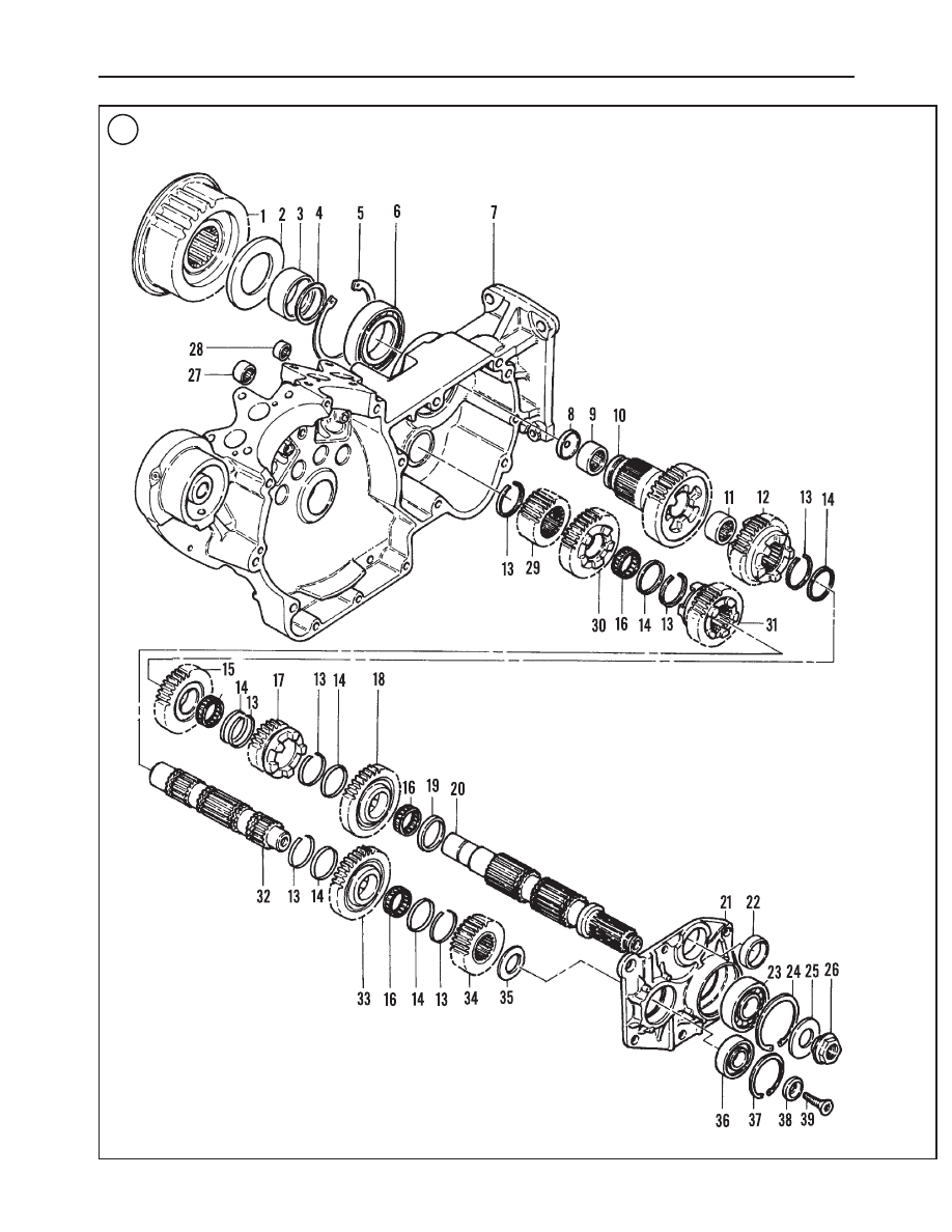
FIVE-SPEED TRANSMISSION (1991-2003 MODELS)

315

9

TRANSMISSION

1. Drive sprocket
2. Oil seal
3. Spacer (drive belt)
4. Quad ring
5. Snap ring
6. Bearing
7. Right crankcase half
8. Seal
9. Needle bearing

10. Main drive gear
11. Needle bearing
12. Mainshaft second gear
13. Snap ring
14. Thrust washer
15. Mainshaft third gear
16. Split bearing
17. Mainshaft first gear
18. Mainshaft fourth gear
19. Spacer
20. Mainshaft
21. Access door
22. Bushing
23. Bearing
24. Snap ring
25. Spring washer
26. Mainshaft nut
27. Countershaft needle bearing
28. Shift shaft needle bearing
29. Countershaft fifth gear
30. Countershaft second gear
31. Countershaft third gear
32. Countershaft
33. Countershaft first gear
34. Countershaft fourth gear
35. Beveled washer
36. Bearing
37. Snap ring
38. Retainer collar
39. Screw

41

42

43

44

316

CHAPTER NINE

45

46

47

48

49

50

51

52

FIVE-SPEED TRANSMISSION (1991-2003 MODELS)

317

9

53

54

55

56

57

58

59

60

b. Insert the mainshaft splined end (C, Figure 71)

through the bearing and center it with the press ram
(Figure 72).

c. Press the mainshaft into the bearing until the

mainshaft shoulder bottoms out against the bearing.

d. Remove the mainshaft/access door assembly from

the press and support it in a vise with soft jaws.

4. Slide the spacer (Figure 73) down the mainshaft and
seat it against the bearing (A, Figure 74).

5. Install the mainshaft fourth gear split bearing and seat it
next to the spacer (B, Figure 74)

318

CHAPTER NINE

61

62

64

63

65

66

67

6. Install mainshaft fourth gear with its shoulder (Figure
75
) facing toward the access door bearing. Slide the gear
over the bearing (Figure 76).

7. Install the thrust washer (Figure 77) and snap ring. Seat
the snap ring in the groove next to 4th gear (Figure 78). Be-
cause of the gear’s recess, push the snap ring into its groove
with a screwdriver.

8. Install mainshaft first gear (Figure 79) so the gear dogs
face toward the access door.

9. Install a snap ring into the second countershaft groove
on the end of the shaft with the internal threads (Figure
80
).

FIVE-SPEED TRANSMISSION (1991-2003 MODELS)

319

9

68

69

70

71

72

73

74

10. Install the thrust washer next to the retaining ring (A,
Figure 81).

11. Install the split bearing next to the thrust washer (B,
Figure 81).

12. Install the countershaft first gear so the gear’s shoulder
faces toward the open snap ring groove. Slide the gear (Fig-
ure 82
) over the bearing.

13. Install the thrust washer (A, Figure 83) and seat it next
to the gear.

14. Install the snap ring (B, Figure 83) into the groove next
to the thrust washer. See Figure 84.

15. Install countershaft fourth gear (A, Figure 85) so the
side with the single radial groove faces the thrust washer in-
stalled in Step 14.

16. Install the bevel washer (B, Figure 85) over the
countershaft so its beveled side faces away from the gear.
Seat the washer next to fourth gear.

17. Press the countershaft (Figure 86) into its access door
bearing as follows:

a. Support the countershaft in a press so that the assem-

bled gear end faces up. Place the bottom of the
countershaft on a press block. See A, Figure 87.

b. Place the access door (B, Figure 87) countershaft

bearing over the countershaft while at the same time
meshing the countershaft and mainshaft gears. Hold
both gear shafts straight up.

320

CHAPTER NINE

75

76

77

78

79

80

CAUTION

The bearing driver must press against the in-
ner bearing race or bearing damage will re-
sult.

c. Place a bearing driver (C, Figure 87) over the inner

countershaft bearing race. Center the bearing driver
underneath the press ram.

d. Bring the press ram into position over the

countershaft, checking that both shafts are straight up
and that both gear sets are properly meshed, then
press the bearing onto the countershaft until the bev-
eled spacers bottom out against the bearing.

FIVE-SPEED TRANSMISSION (1991-2003 MODELS)

321

9

81

82

83

84

85

86

87

e. Release the press ram and check countershaft fourth

gear. When properly installed, countershaft fourth
gear should have no end play.

18. Secure the access door in a vise with soft jaws.

19. Install the snap ring and thrust washer (Figure 88) onto
the mainshaft. Seat the snap ring in the groove next to
mainshaft first gear.

20. Install the mainshaft third gear split bearing (Figure
89
) next to the thrust washer.

21. Install mainshaft third gear (Figure 90) over the split
bearing so that the gear dogs face up.

22. Install the thrust washer and snap ring. Seat the snap
ring (Figure 91) in the groove next to mainshaft third
gear.

23. Install countershaft third gear (Figure 92) so its gear
dogs face away from the access cover.

24. Install the countershaft snap ring (A, Figure 93) and
thrust washer (B). Seat the snap ring in the groove next to
the countershaft third gear.

25. Install the countershaft split bearing (Figure 94) next
to countershaft third gear.

26. Install countershaft second gear (Figure 95) over the
split bearing. Install the gear so its gear dogs face the access
cover.

27. Install mainshaft second gear (Figure 96) so that the
side with the shift fork groove is toward the access cover.

28. Install countershaft fifth gear (Figure 97).

322

CHAPTER NINE

88

89

90

91

92

93

29. Install the snap ring into the groove next to
countershaft fifth gear (Figure 98).
30. Install the shift forks and shift drum as described in this
chapter.

MAIN DRIVE GEAR

Two tools are required to remove and install the main

drive gear located in the right crankcase half. Removing the
main drive gear without these tools, may cause crankcase
and/or main drive gear damage.
1. Main drive gear remover and installer (part No.
HD-35316A). See Figure 99 and A, Figure 100.
2. Cross plate (part No. HD35316-91). See B, Figure 100.

FIVE-SPEED TRANSMISSION (1991-2003 MODELS)

323

9

94

95

96

97

98

99

100

Refer to Figure 101.

Removal

1. Remove the transmission as described in this chapter.

2. Remove the spacer ring (A, Figure 102) and quad ring
(B) from the main drive gear.

3. Tap out the seal (A, Figure 103) that is mounted in the
end of the main drive gear. Use a drift inserted through the
main drive gear as shown in B, Figure 103. Discard the
seal.

4. Assemble the main drive gear remover and installer and
the cross plate as shown in Figure 104. Refer to Figure 105
and Figure 106.

324

CHAPTER NINE

101

MAIN DRIVE GEAR ASSEMBLY

1. Drive sprocket
2. Oil seal
3. Spacer (drive belt)
4. Quad ring
5. Snap ring
6. Bearing
7. Right crankcase half
8. Seal
9. Needle bearing

10. Main drive bearing (fifth gear)

102

103

CAUTION

Whenever the main drive gear is removed, the
main drive gear bearing must be replaced.

NOTE

Insert the two cross plate pins into the pin
holes in the transmission housing. This will
center the cross plate over the main drive
gear.

5. Tighten the puller nut (B, Figure 106) to push the main
drive gear from the main drive gear bearing. Remove the
nut and puller bolt, and then remove the main drive gear
(Figure 107) from the transmission portion of the engine
crankcase. Disassemble and remove the puller and cross
plate assembly. Discard the bearing
6. Pry the main drive gear oil seal (2, Figure 101) out of
the right crankcase half.
7. Replace the main drive gear bearing as described in

Right Transmission Case Bearings

in this chapter.

Inspection

1. Clean the main drive gear in solvent and dry with com-
pressed air.
2. Check each gear tooth (Figure 108) for excessive
wear, burrs, galling and pitting. Check for missing gear
teeth.
3. Check the gear splines for severe wear, galling or other
damage.
4. Inspect the two main drive gear needle bearings (Figure
109
) for severe wear or damage. Insert the mainshaft into
the main drive gear to check bearing wear. If necessary, re-
place the bearings as described in this section.

Main Drive Gear Needle Bearing Replacement

Both mainshaft drive gear needle bearings (9, Figure 101)

must be installed to a specific depth (Figure 110). Bearing
installation can be aided with the inner/outer main drive gear
needle bearing installation tool (part No. HD-37842 for
1991-1994 models and part No. HD-37842A for 1995-2003

FIVE-SPEED TRANSMISSION (1991-2003 MODELS)

325

9

104

Crankcase

Cross plate

Bolt

5th gear

Driver

Nut

Thrust washer

105

106

107

108

models). This tool installs the bearing to the specified depth.
If not using the tool, it is necessary to measure bearing depth
when installing the new bearings

Always replace both main drive gear needle bearings at

the same time.

CAUTION

Do not install a main drive gear needle bear-
ing that has been removed. Removal damages
the bearings.

1. Support the main drive gear in a press and press out both
needle bearings.

2. Clean the bearing bore in solvent and dry thoroughly.

NOTE

Install both needle bearings with their manu-
facturer’s name and size code facing out.

3A. The inner/outer main drive gear needle bearing instal-
lation tool is stamped with two sets of numbers. The side
stamped 0.080 is for pressing in the inner end bearing and is
the same for all years. The side stamped 0.285 (1991-1994
models) or 0.315 (1995-2003 models) is for pressing the
outer end bearing. Figure 110 identifies the main drive gear
inner and outer ends.

a. Install the main drive gear in a press with the outer

end facing up. Align the new bearing with the main
drive gear and install the installation tool. Be sure the
side stamped 0.285 (1991-1994 models) or 0.315
(1995-2003 models) is inserted into the bearing.
Press the bearing until the tool bottoms.

b. Turn the main drive gear over so that the inner end

faces up. Align the new bearing with the main drive
gear and install the installation tool with the side
marked 0.080 inserted into the bearing. Press the
bearing until the tool bottoms.

3B. If bearing installation tools are not available, perform
the following. Figure 110 identifies the main drive gear in-
ner and outer ends.

326

CHAPTER NINE

109

110

Outer end

0.03-0.06 in.
(0.76-1.52 mm)

Plug seal

Main drive

gear

Inner end

Needle bearings

0.080 in.
(2.032 mm)

1991-1994 models:
0.27-0.30 in.
(6.86-7.62 mm)
1995-2003 models:
0.285-0.315 in.
(7.239-8.001 mm)

111

112

a. Using a suitable mandrel, press in the outer end bear-

ing to the depth indicated in Figure 110.

b. Using a suitable mandrel, press in the inner end bearing

to a depth of 0.080 in. (2.032 mm). See Figure 110.

Main Drive Gear Installation

1. Replace the main drive gear bearing (6, Figure 101) as
described in

Right Transmission Case Bearings

in this

chapter.

2. Coat the oil seal lips with transmission oil prior to instal-
lation.

3. Slide the oil seal (2, Figure 101), with its lips facing to-
ward the crankcase, over the spacer. Tap the oil seal (Fig-
ure 111
) into the crankcase until its outer surface is flush
with or slightly below (0.030 in. [0.76 mm] maximum) the
oil seal bore inside surface.

4. Insert the main drive gear (Figure 107) into the main
drive gear bearing in the transmission portion of the engine
crankcase as far as it will go (Figure 112). Then hold it in
place and assemble the main drive gear remover and in-
staller tool as shown in Figure 113 and A, Figure 114.

CAUTION

Note how the installer cup, shown in

Figure

115

, supports the main drive gear bearing in-

ner race. If using a different tool setup, make
sure the inner bearing race is supported in
the same way. Otherwise, the bearing will be
damaged when the main drive gear is pressed
into place.

5. Tighten the puller nut (B, Figure 114) to pull the main
drive gear through the bearing. Continue until the gear
shoulder bottoms against the inner bearing race.

6. Remove the installer tool.

7. Install a new seal (Figure 116) into the end of the main
drive gear until its outer surface is 0.03-0.06 in. (0.76-1.52
mm) below the bearing bore inside surface as indicated in
Figure 110.

8. Install a new quad ring (A, Figure 117) over the threaded
portion of fifth gear and position it next to the gear taper.

FIVE-SPEED TRANSMISSION (1991-2003 MODELS)

327

9

113

114

115

Crankcase

Thrust washer

Bolt

Nut

Installer cup

5th gear

Washer

116

117

9. Slide the spacer (B, Figure 117), with its chamfered end
facing the quad ring, over fifth gear and seat it against the
bearing. See Figure 118.
10. Install the transmission as described in this chapter.

ACCESS DOOR BEARINGS

The access door is equipped with the following:

1. Mainshaft bearing (A, Figure 119).
2. Countershaft bearing (B, Figure 119).
3. Shift drum bushing (C, Figure 119).

Mainshaft/Countershaft Bearings Inspection

WARNING

Do not spin the bearings with compressed air.
Compressed air will spin the bearings at
speeds in excess of their designed capacity.
This may cause the bearing to fly apart,
which may cause eye damage or other inju-
ries.

1. Clean both bearings in kerosene. Hold the inner bearing
race with your fingers and dry the bearing with compressed
air.
2. Turn the inner bearing race slowly. The bearing should
turn smoothly with no roughness, binding or excessive
play. If these conditions are noted, reclean and dry the bear-
ing. If these conditions still persist, replace the bearing as
described in this section.
3. If the bearing does not turn smoothly, check for damage.
Also check the bearing fit in the bearing bore; both bearings
must be a tight fit. If the bearing is a loose fit, check the ac-
cess door for cracks or other damage.
4. Replace the bearings, if necessary, as described in this
section.
5. If the bearings can be reused, lubricate them thoroughly
with new transmission oil, then place the access door in a
plastic bag and seal it until transmission reassembly.

Shift Drum Bushing Inspection

1. Clean the bushing (C, Figure 119) with solvent or kero-
sene. Dry with compressed air.
2. Inspect the bushing for scoring, overheating, galling or
excessive wear.
3. Replace the bushing, if necessary, as described in this
section.

Mainshaft/Countershaft Bearing Replacement

This procedure can be used to replace both bearings.

1. Remove the bearing circlip.
2. Support the access door, with its inside surface facing
up, in a press.

CAUTION

Make sure the access door is positioned so
that it is not resting on the shift drum retain-
ing pin. Otherwise, the access door will be
damaged when pressure is applied to it.

3. Using a suitable mandrel or bearing driver, press the
bearing out of the access door.

328

CHAPTER NINE

118

119

120

0.02 in. (0.51 mm)

Shift drum bushing

Shift drum snap ring

4. Clean the bearing bore and dry with compressed air.

5. Check the circlip groove for severe wear, cracks or other
damage. If the groove is damaged, replace the access door.

6. Support the access door, with its outside surface facing
up, in a press.

NOTE

Install both bearings with the manufacturer’s
name and size code facing out.

7. Place a bearing driver on the outer bearing race and
press the bearing into the access cover until the bearing bot-
toms out.

8. Install a new circlip, with the beveled side facing away
from the bearing, into the access door groove. Make sure
the circlip is fully seated in the groove.
9. Repeat for the opposite bearing.

Shift Drum Bushing Replacement

1. Support the access door in a press and press out the
bushing from either side.
2. Clean the bushing bore in kerosene and dry with com-
pressed air.
3. Support the access door, with its outside surface facing
down, in a press.
4. Press in the bushing until its outer surface is flush with
or 0.02 in. (0.51 mm) below the bushing bore inside surface
as shown in Figure 120.

RIGHT TRANSMISSION CASE BEARINGS

The right transmission case is equipped with the follow-

ing bearings:
1. Main drive gear bearing (A, Figure 121).
2. Countershaft needle bearing (A, Figure 122).
3. Shift drum needle bearing (B, Figure 122).

Each of these bearings can be replaced with the engine

crankcase assembled and installed in the frame.

Main Drive Gear Bearing Inspection

Because the main drive gear bearing (A, Figure 121) is

damaged when the main drive gear is removed, do not at-
tempt to reuse the bearing. Replace the bearing as described
in this section.

Countershaft and Shift Drum Needle
Bearings Inspection

1. Clean both needle bearings (A and B, Figure 122) in
kerosene and dry with compressed air.
2. Check the needle bearings for worn, loose or damaged
rollers. Check the roller cage and outer shell for damage.
3. Check each bearing for a loose fit in its bore. If the bear-
ing is a loose fit, check the access door for cracks or other
damage.
4. Replace the bearings, if necessary, as described in this
section.
5. If the bearings can be reused, lubricate them thoroughly
with new transmission oil.

Main Drive Gear Bearing Replacement

Refer to Figure 101.

1. Pry the main drive gear bearing oil seal (Figure 123) out
of the crankcase. Pad the screwdriver to avoid damaging
the crankcase.

FIVE-SPEED TRANSMISSION (1991-2003 MODELS)

329

9

121

122

123


Content      ..     30      31      32      33     ..