Harley Davidson 1986-2003 XL/XLH Sportster. Service Manual - page 28
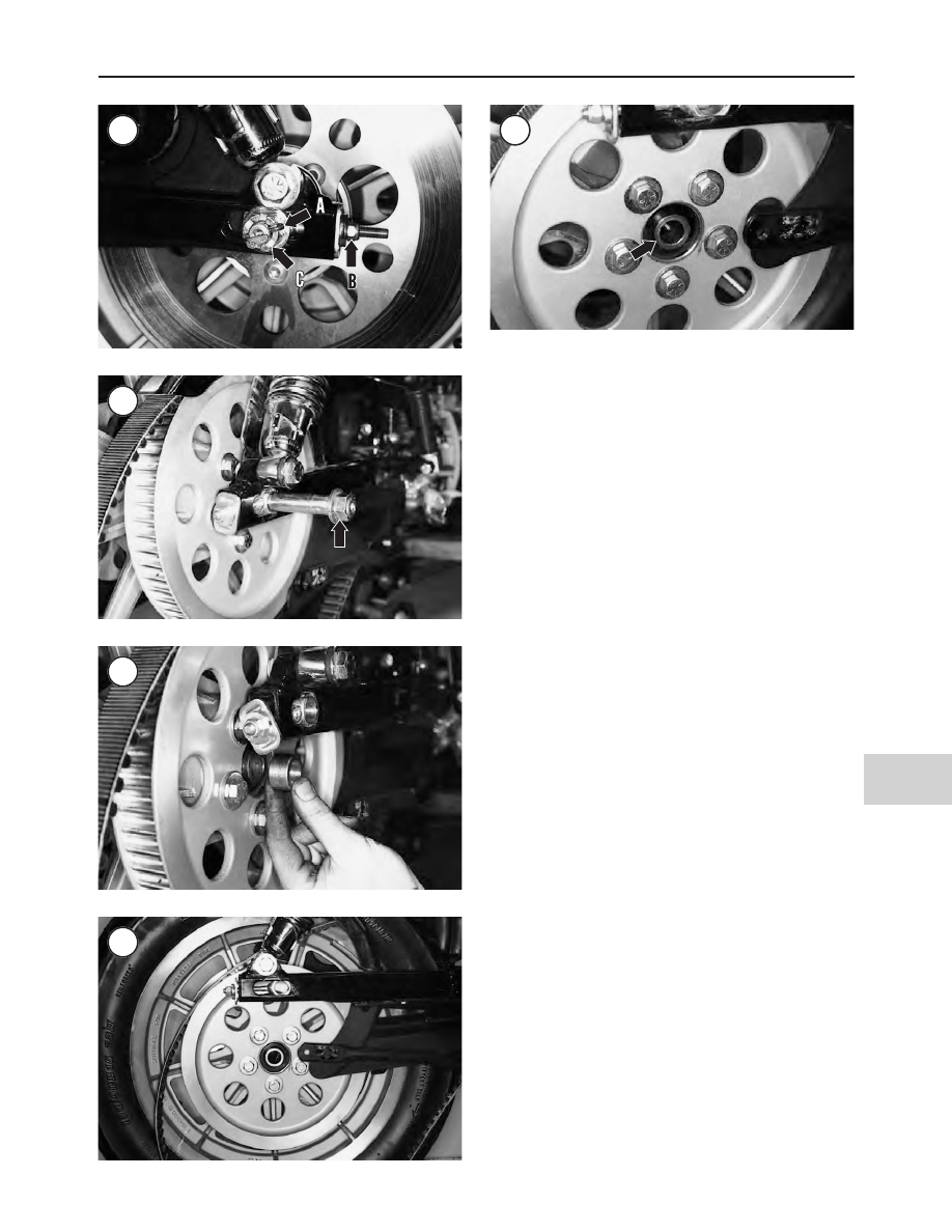
5. Slide the axle out of the wheel (Figure 28) and allow the
wheel to drop to the ground.
NOTE
Identify the wheel spacers during removal so
they can be returned to their original positions.
6. Remove the outer right axle spacer (Figure 29).
CAUTION
Do not set the wheel down on the brake disc
surface, as it may be damaged.
NOTE
On 1986-1999 models, the shoulders on the
inner left and right axle spacers are inserted
through the seal. These spacers should not
fall out when the wheel is removed.
7. Lift the drive chain or belt off the sprocket and remove
the rear wheel (Figure 30).
8. Place a spacer between the brake pads in place of the
disc. With the spacer in place, if the brake lever is inadver-
tently applied, the pistons will not be forced out of the cali-
per. If the pistons are forced out, disassemble the caliper to
reseat the pistons as described in Chapter Sixteen.
9. Inspect the rear wheel assembly as described in this chapter.
Installation
1. Clean the axle in solvent and dry thoroughly. Make sure
the axle bearing surfaces on the axle are free from burrs and
nicks.
2. Apply a film of waterproof bearing grease to the axle
shaft prior to installation.
3. On 1986-1999 models, make sure the inner left and right
axle spacers are inserted through the seal as shown in Fig-
ure 31. If necessary, install the spacers and oil seals as de-
scribed in
Rear Hub
in this chapter
4. Remove the spacer from between the brake caliper.
Then position the rear wheel into the swing arm, through
the drive chain or belt, and position the right axle spacer
(Figure 29) between the swing arm and wheel.
5. Lift the wheel into position and install the axle (Figure
28) from the right side.
WHEEL, TIRES AND SECONDARY DRIVE
475
13
27
28
29
30
31