Harley Davidson 1986-2003 XL/XLH Sportster. Service Manual - page 24
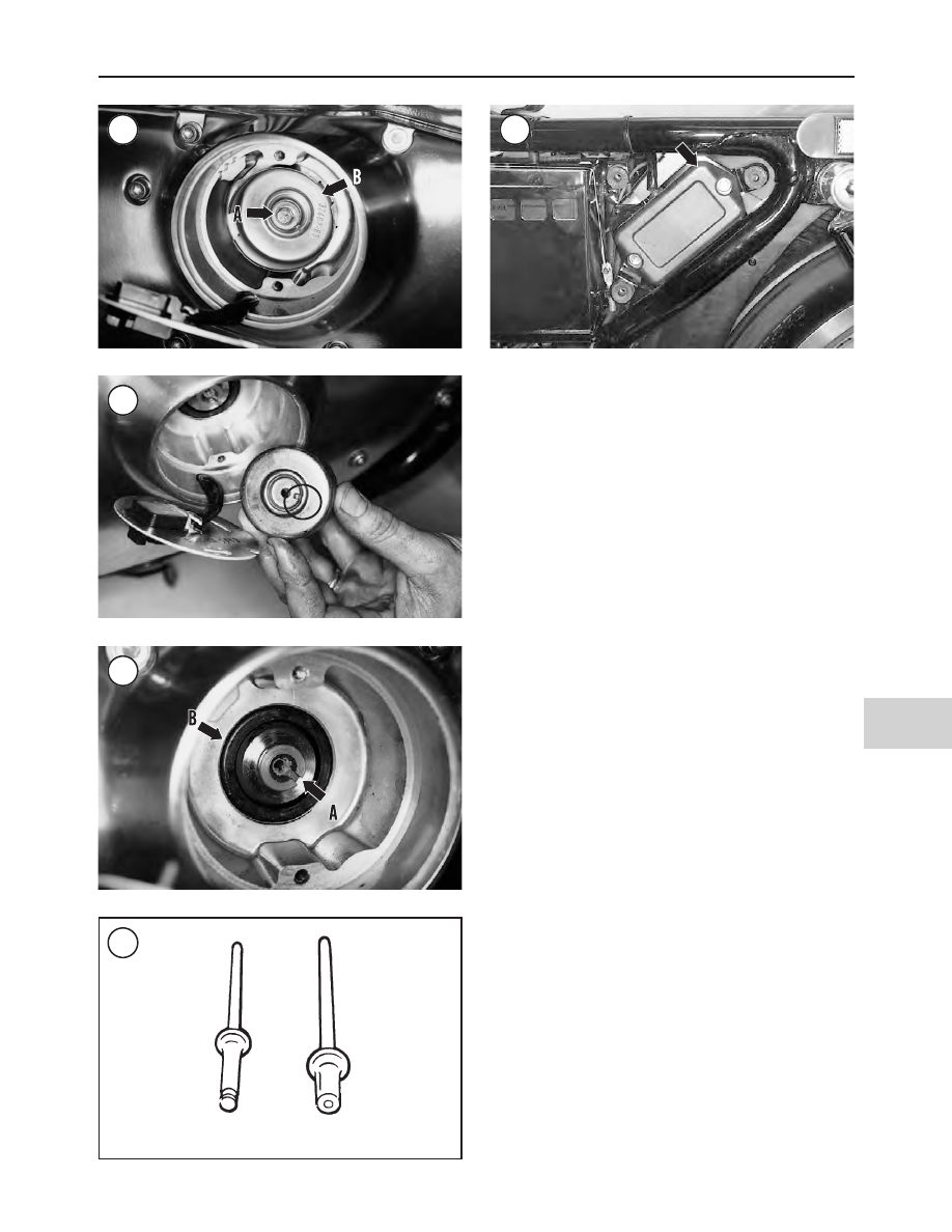
14. Before riveting the cover in place, check the ignition
timing as described in Chapter Three.
CAUTION
Be sure to use the correct rivets when install-
ing the inner and outer covers. These are tim-
ing cover rivets which do not have ends that
will fall into the timing compartment and
damage the ignition components.
15. Rivet the outer cover to the inner cover. Only use origi-
nal equipment rivets (part No. 8699) to secure the outer
cover. See Figure 51 and Figure 43.
Inspection
1. If necessary, refer to Chapter Two for troubleshooting.
2. Check the ignition compartment for oil leaks. If present,
remove the gearcase oil seal (B, Figure 50) by prying it out
with a screwdriver or seal remover. Install a new seal by
tapping it in place with a suitable size socket placed on the
outside of the seal. Drive the seal into position so it is flush
with the seal bore surface. If the gearcase oil seal is not
seated properly, it will leak.
Ignition Module
Removal/Installation
The ignition module (Figure 52) is mounted on the left
side of the motorcycle to the rear of the battery.
1. Disconnect the negative battery cable as described in
this chapter.
2. Remove the ignition module cover.
3A. On 1986-1994 models, disconnect the ignition module
wires from the ignition coil. Remove the ground wire con-
nection at the frame.
3B. On 1995-1997 models, disconnect the igntion module
connector from the wiring harness.
4. Remove the ignition module assembly (Figure 52).
5. Install by reversing the preceding steps. On 1995-1997
models, tighten the ignition module bolts to 15-20 in.-lb.
(1.5-2 N•m).
ELECTRICAL SYSTEM
411
12
48
49
50
51
Incorrect
Correct
52