Harley Davidson 1986-2003 XL/XLH Sportster. Service Manual - page 22
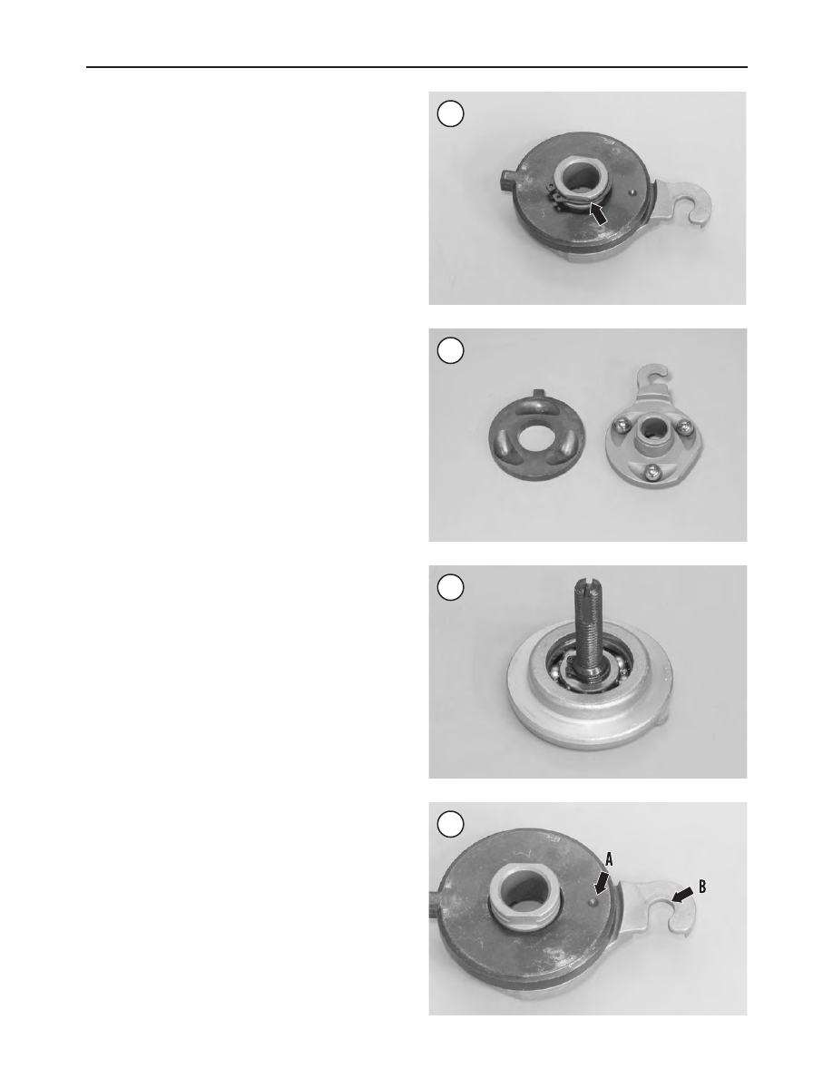
3. Remove the clutch spring cover.
4. Remove the quad ring (A, Figure 14).
5. Remove the spring and lockplate (B, Figure 14).
6. Turn the clutch adjusting screw (A, Figure 15) clock-
wise and release the ramp (B) and coupling (C). Turn the
clutch adjusting screw clockwise to move the ramp assem-
bly forward. Then unscrew the nut (D, Figure 15) from the
end of the adjusting screw and remove it.
7. Pivot the hook on the ramp to the rear of the cable end cou-
pling. Disconnect and remove the clutch cable from the slot in
the coupling. Remove the coupling and ramp assembly.
8. Remove the snap ring (Figure 22) securing the inner
and outer ramp halves. Separate the halves and remove the
ramps and balls.
Inspection
1. Wash the clutch release mechanism in solvent and dry
thoroughly.
2. Check the balls and ramp sockets (Figure 23) for pit-
ting, severe wear or other damage.
3. Check the adjusting screw (Figure 24) for thread or
bearing damage.
4. Replace the lockplate if the tabs are weak or broken.
5. Replace severely worn or damaged parts as required.
Installation
Refer to Figure 12.
1. Apply grease to the ball and ramp surfaces (Figure 23)
and insert the balls into the outer ramp sockets.
2. Install the inner ramp on the outer ramp hook so the
punch mark (A, Figure 25) on the inner ramp aligns with
the hook of the outer ramp (B).
3A. On 1994-1996 models, install the coupling onto the
cable end with the rounded side facing out and the ramp
connector button facing in.
3B. On 1997-2003 models, install the coupling onto the
cable end with the rounded side facing in and the ramp
connector button facing out. With the retaining side of the
ramp facing in, install the ramp hook around the coupling
button. Then rotate the assembly counterclockwise until
the tang on the inner ramp fits into the primary drive cover
slot.
4. Thread the nut onto the clutch adjusting screw until the
slot in the end of the screw is accessible with a screwdriver.
Then align and install the hex portion on the nut into the
outer ramp recess (Figure 26). Turn the clutch adjusting
screw counterclockwise until resistance is felt, then back
off 1/4 turn.
5. Adjust the clutch as described in Chapter Three. The
spring and lockplate shown in B, Figure 14 will be in-
stalled during the clutch adjustment procedure.
270
CHAPTER SEVEN
22
23
24
25