Ford Mondeo (petrol engines). Manual - part 100
 

  Index      Ford     Ford Mondeo - service and repair manual (petrol engines)


Search            


Content   ..  98  99  100  101   ..


Ford Mondeo (petrol engines). Manual - part 100


EGR valve, and check the valve and the
inlet manifold for blockage. Clean or
renew parts as necessary, and recheck.

EGR system

Any further checking of the system requires
special tools and test equipment. Take the
vehicle to a dealer service department for
checking.

Component renewal

Note: These components will be very hot
when the engine is running. Always allow the
engine to cool down fully before starting work,
to prevent the possibility of burns.

EGR valve

Disconnect the battery negative (earth) lead
- see Section 1 of Chapter 5.
Remove the air mass meter and resonator -
refer to Chapter 4.
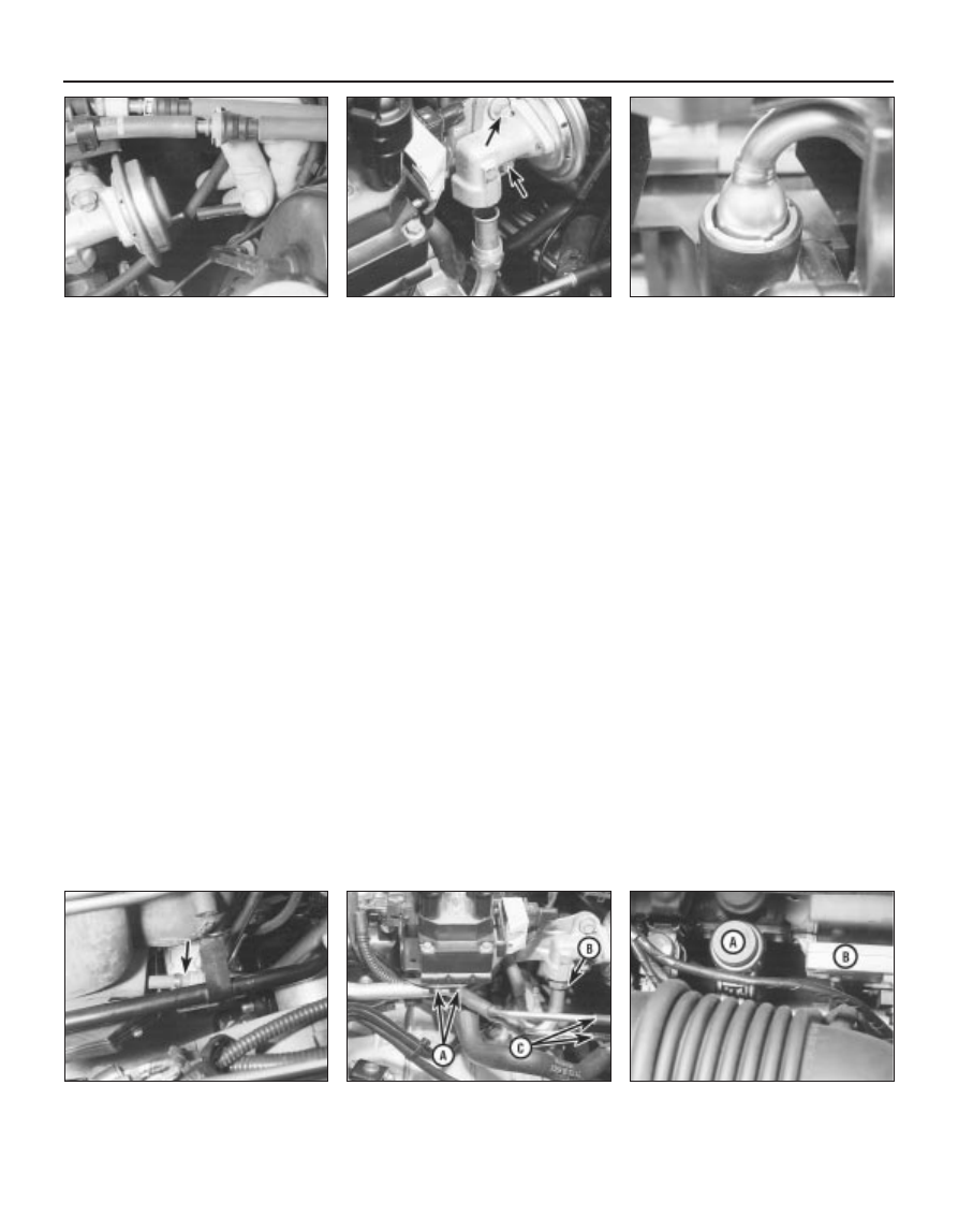
Detach the vacuum hose, unscrew the
sleeve nut securing the EGR pipe to the valve,
remove the two valve mounting bolts, and
withdraw the valve from the inlet manifold
(see illustrations). Ensure that the end of the
pipe is not damaged or distorted as the valve
is withdrawn, and note the valve’s gasket; this
must be renewed whenever the valve is
disturbed.
10 Note that the metal pipe from the valve to
the manifold itself should not be disturbed - it
is not available separately from the manifold.

However, check whenever the manifold is
removed that the pipe’s end fitting is securely
fastened (see illustration).
11 Check the valve for sticking and heavy
carbon deposits. If such is found, clean the
valve or renew it.
12 Refitting is the reverse of the removal
procedure. Apply a smear of anti-seize
compound to the sleeve nut threads, fit a new
gasket, and tighten the valve bolts to the
specified torque wrench setting.

EGR pipe

13 Disconnect the battery negative (earth)
lead - see Section 1 of Chapter 5.
14 Remove the air mass meter and resonator
- refer to Chapter 4.
15 Unbolt the exhaust manifold heat shield
and remove both parts, or move them aside
as required to reach the end of the EGR pipe.
Unscrew the sleeve nut securing the pipe to
the exhaust manifold (see illustration).
16 Undo the two screws securing the pipe to
the ignition coil bracket, then disconnect the
two vacuum hoses - note that these are of
different sizes, to ensure that they cannot be
mixed up on reconnection. Unscrew the
sleeve nut securing the EGR pipe to the valve
(see illustration). Withdraw the pipe.
17 Check the condition of both hoses, and
renew them if necessary (see Chapter 1). Note
that if the exhaust gases have been backfiring
excessively - eg, due to a blocked exhaust
system - both hoses must be renewed, and

their connections on the pipe must be cleaned
thoroughly.
18 Refitting is the reverse of the removal
procedure; ensure that the hoses are securely
connected to the correct unions. Apply a
smear of anti-seize compound to the sleeve
nut threads, tighten the nuts securely, and
tighten the two screws to their specified
torque wrench setting.

EGR exhaust gas pressure differential
sensor

19 Refer to Section 4 of this Chapter.

EGR solenoid valve

Note: This component can be identified by its
larger top and its two fastening screws. Do not
confuse it with the adjacent pulse-air solenoid
valve, especially when reconnecting vacuum
hoses.
20 Disconnect the battery negative (earth)
lead - see Section 1 of Chapter 5.
21 Remove the air mass meter and resonator
- refer to Chapter 4. If better access is
required, remove the plenum chamber also
(see illustration).
22 Releasing its wire clip, unplug the
electrical connector from the valve. Remove
the two retaining screws, and withdraw the
valve from the bulkhead mounting bracket,
then label and disconnect the two vacuum
hoses.
23 Refitting is the reverse of the removal
procedure; ensure that the hoses are correctly
reconnected.

6•16 Emissions control systems

6.9A  Disconnecting vacuum hose from

Exhaust Gas Recirculation (EGR) valve . . .

6.9B  . . . unscrew EGR pipe sleeve nut and

remove bolts (arrowed) to release valve

from inlet manifold

6.10  Check end fitting of EGR pipe into

inlet manifold whenever manifold is

removed, but do not disturb

6.15  Unbolt exhaust manifold heat shield,

and unscrew sleeve nut (arrowed) securing

EGR pipe to exhaust manifold . . .

6.16  . . . undo screws “A” and sleeve 

nut “B”, then disconnect hoses “C” - note

different sizes - to release EGR pipe

6.21  EGR solenoid valve “A” and EGR

exhaust gas pressure differential sensor

“B”, located on bulkhead mounting bracket

General information

This system consists of the pulse-air
solenoid valve, the pulse-air valve itself,
contained in the filter housing, and the piping
- see illustration 2.1A. It injects filtered air
directly into the exhaust ports, using the
pressure variations in the exhaust gases to
draw air through from the filter housing; air will
flow into the exhaust only when its pressure is
below atmospheric. The pulse-air valve can
allow gases to flow only one way, so there is
no risk of hot exhaust gases flowing back into
the filter.
The system’s primary function is raise
exhaust gas temperatures on start-up, thus
reducing the amount of time taken for the
oxygen sensor and catalytic converter to
reach operating temperature. Until this
happens, the system reduces emission of
unburned hydrocarbon particles (HC) and
carbon monoxide (CO) by ensuring that a
considerable proportion of these substances
remaining in the exhaust gases after
combustion are burned up, either in the
manifold itself or in the catalytic converter.
To ensure that the system does not upset
the smooth running of the engine under
normal driving conditions, it is linked by the
pulse-air solenoid valve to the ECU, so that it
only functions during engine warm-up, when
the oxygen sensor is not influencing the
fuel/air mixture ratio.

Checking

Poor idle, stalling, backfiring and poor
driveability can be caused by a fault in the
system.
Inspect the vacuum pipe/hose connected
between the filter housing and the solenoid
valve for kinks, leaks and cracks along its
entire length. Repair or renew as necessary.
Inspect the filter housing and piping. If
either is cracked or damaged, renew it.

If the pulse-air solenoid valve is thought to
be faulty, unplug its electrical connector and
disconnect its vacuum hoses. Connect a
battery directly across the valve terminals,
and check that air can flow through the valve
passages when the solenoid is thus
energised, and that nothing can pass when
the solenoid is not energised. Alternatively,
connect an ohmmeter to measure the
resistance across the valve terminals, and
compare this reading to the one listed in the
Specifications Section at the beginning of this
Chapter. Renew the solenoid valve if it is
faulty.
Further testing should be left to a dealer
service department.

Component renewal

Pulse-air solenoid valve

Note: This component can be identified by its
smaller top and its clip fastening. Do not
confuse it with the adjacent EGR solenoid
valve, especially when reconnecting vacuum
hoses.
Disconnect the battery negative (earth) lead
- see Section 1 of Chapter 5.
10 Remove the air mass meter and resonator
- refer to Chapter 4. If better access is
required, remove the plenum chamber also
(see illustration).
11 Releasing its wire clip, unplug the
electrical connector, then use a small
screwdriver to release the clip securing the
valve to the bulkhead mounting bracket.

Withdraw the valve, then label and disconnect
the two vacuum hoses.
12 Refitting is the reverse of the removal
procedure; ensure that the hoses are correctly
reconnected.

Pulse-air filter housing

Note: This component, and those around it,
will be very hot when the engine is running.
Always allow the engine to cool down fully
before starting work, to prevent the possibility
of burns.
13 Raise the front of the vehicle, and support
it securely on axle stands. Disconnect the
vacuum hose from the base of the filter
housing (see illustration).
14 Disconnect the battery negative (earth)
lead - see Section 1 of Chapter 5.
15 Unbolt the resonator support bracket
from the engine compartment front
crossmember, slacken the two clamp screws
securing the resonator to the air mass meter
and plenum chamber hoses, then swing the
resonator up clear of the thermostat housing
(see Chapter 4).
16 Remove the screws securing the filter
housing to the piping, unscrew the mounting
bolt, then withdraw the housing (see
illustration)
.
17 To dismantle the filter housing, undo the
four screws and separate the top from the
base of the housing; extract the foam filter,
and clean it in a suitable solvent (see
illustrations)
. If any of the housing’s

7 Pulse-air system 

general information

Emissions control systems  6•17

6

7.17A  Remove four screws to release filter

housing top from base . . .

7.17B  . . .and withdraw foam filter for

cleaning, if required - note valve in base of

housing

7.10  Pulse-air solenoid valve (arrowed) is

located on bulkhead mounting bracket. It

can be identified by its smaller top and its

clip fastening - do not confuse it with the

adjacent EGR solenoid valve

7.13  Disconnect vacuum hose from base

of pulse-air filter housing . . .

7.16  . . . undo screws “A” to disconnect

piping from housing, and mounting 

bolt “B” to release housing

components are worn or damaged, the
assembly must be renewed.
18 Refitting is the reverse of the removal
procedure.

Pulse-air piping

Note: This component, and those around it,
will be very hot when the engine is running.
Always allow the engine to cool down fully
before starting work, to prevent the possibility
of burns.
19 Disconnect the battery negative (earth)
lead - see Section 1 of Chapter 5.
20 Remove the air mass meter and resonator
- refer to Chapter 4.
21 Unbolt the exhaust manifold heat shield;
unclip the coolant hose to allow the upper
part to be withdrawn. Apply penetrating oil to
the EGR pipe sleeve nut, and to the pulse-air
system sleeve nuts.
22 Remove the EGR pipe (see Section 6).
23 Remove the screws securing the filter
housing to the piping - see illustration 7.16.
Unscrew the four sleeve nuts securing the
pipes into the exhaust manifold, and remove
the piping as an assembly, taking care not to
distort it (see illustration).
24 Carefully clean the piping, particularly its
threads and those of the manifold, removing
all traces of corrosion, which might prevent
them seating properly, causing air leaks when
the engine is restarted.
25 On refitting, insert the piping carefully into
the cylinder head ports, taking care not to
bend or distort it. Apply anti-seize compound
to the threads, and tighten the retaining sleeve
nuts while holding each pipe firmly in its port;
if a suitable spanner is available, tighten the
sleeve nuts to the specified torque wrench
setting.
26 The remainder of the refitting procedure is
the reverse of removal.

Pulse-air filter housing and piping
assembly

Note: These components, and those around
them, will be very hot when the engine is
running. Always allow the engine to cool down
fully before starting work, to prevent the
possibility of burns.
27 Disconnect the battery negative (earth)
lead - see Chapter 5, Section 1. Unbolt the

resonator support bracket from the engine
compartment front crossmember. Slacken the
two clamp screws securing the resonator to
the air mass meter and plenum chamber
hoses, then swing the resonator up clear of
the thermostat housing (see Chapter 4).
28 Drain the cooling system (see Chapter 1)
and disconnect the coolant hose and the
coolant pipe/hose from the thermostat
housing.
29 Unbolt the exhaust manifold heat shield.
Apply penetrating oil to the EGR pipe sleeve
nut, and to the pulse-air system sleeve nuts.
30 Remove the EGR pipe (see Section 6).
31 Unscrew the filter housing mounting bolt.
Unscrew the four sleeve nuts securing the
pipes into the exhaust manifold and remove
the assembly, taking care not to distort it (see
illustration)
.
32 Clean the piping, particularly its threads
and those of the manifold, removing all traces

of corrosion, which might prevent them
seating properly, causing air leaks when the
engine is restarted.
33 On refitting, insert the piping carefully into
the cylinder head ports, taking care not to
bend or distort it. Apply anti-seize compound
to the threads, and tighten the retaining sleeve
nuts while holding each pipe firmly in its port;
if a suitable spanner is available, tighten the
sleeve nuts to the specified torque wrench
setting.
34 The remainder of the refitting procedure is
the reverse of removal. Refill the cooling
system (see Chapter 1). Run the engine,
check for exhaust leaks, and check the
coolant level when it is fully warmed-up.

General information

The crankcase ventilation system main
components are the oil separator mounted on
the front (radiator) side of the cylinder
block/crankcase, and the Positive Crankcase
Ventilation (PCV) valve set in a rubber
grommet in the separator’s left-hand upper
end. The associated pipework consists of a
crankcase breather pipe and two flexible
hoses connecting the PCV valve to a union on
the left-hand end of the inlet manifold, and a
crankcase breather hose connecting the
cylinder head cover to the air cleaner
assembly 

(see illustration). A small foam filter

in the air cleaner prevents dirt from being
drawn directly into the engine.

8 Positive Crankcase Ventilation

(PCV) system 
general information

6•18 Emissions control systems

7.23  Removing pulse-air piping - take care

not to bend or distort it

7.31  Remove mounting bolt (arrowed) to

remove complete pulse-air assembly -

again, take care not to bend or distort

piping

8.1  Positive Crankcase Ventilation system

1  Oil separator
2  Gasket
3  Positive Crankcase Ventilation (PCV) valve

4  Cylinder block/crankcase opening
5  Crankcase breather pipe and flexible hoses

The function of these components is to
reduce the emission of unburned
hydrocarbons from the crankcase, and to
minimise the formation of oil sludge. By
ensuring that a depression is created in the
crankcase under most operating conditions,
particularly at idle, and by positively inducing
fresh air into the system, the oil vapours and
“blow-by” gases collected in the crankcase
are drawn from the crankcase, through the oil
separator, into the inlet tract, to be burned by
the engine during normal combustion.

Checking

Checking procedures for the system
components are included in Chapter 1.

Component renewal

Cylinder head-to-air cleaner hose

See Chapter 1.

Positive Crankcase Ventilation (PCV)
valve

The valve is plugged into the oil separator.
Depending on the tools available, access to
the valve may be possible once the pulse-air
assembly has been removed (see Section 7).
If this is not feasible, proceed as outlined in
paragraph 6 below.

Oil separator

Remove the exhaust manifold (see Chap-
ter 2, Part A). The Positive Crankcase
Ventilation (PCV) valve can now be unplugged
and flushed, or renewed, as required, as
described in Chapter 1.
Unbolt the oil separator from the cylinder
block/crankcase, and withdraw it; remove and
discard the gasket.
Flush out or renew the oil separator, as
required (see Chapter 1).
On reassembly, fit a new gasket, and
tighten the fasteners to the torque wrench
settings given in the Specifications Section of
Chapter 2, Part B.
10 The remainder of the refitting procedure is
the reverse of removal. Refill the cooling
system (see Chapter 1). Run the engine,
check for exhaust leaks, and check the
coolant level when it is fully warmed-up.

General information

The exhaust gases of any petrol engine
(however efficient or well-tuned) consist
largely (approximately 99 %) of nitrogen (N

2

),

carbon dioxide (CO

2

), oxygen (O

2

), other inert

gases and water vapour (H

2

O). The remaining

1 % is made up of the noxious materials
which are currently seen (CO

2

apart) as the

major polluters of the environment: carbon
monoxide (CO), unburned hydrocarbons (HC),

oxides of nitrogen (NO

x

) and some solid

matter, including a small lead content.
Left to themselves, most of these pollutants
are thought eventually to break down naturally
(CO and NO

x

, for example, break down in the

upper atmosphere to release CO

2

) having first

caused ground-level environmental problems.
The massive increase world-wide in the use of
motor vehicles, and the current popular
concern for the environment has caused the
introduction in most countries of legislation, in
varying degrees of severity, to combat the
problem.
The device most commonly used to clean
up vehicle exhausts is the catalytic converter.
It is fitted into the vehicle’s exhaust system,
and uses precious metals (platinum and
palladium or rhodium) as catalysts to speed
up the reaction between the pollutants and
the oxygen in the vehicle’s exhaust gases, CO
and HC being oxidised to form H

2

O and CO

2

and (in the three-way type of catalytic
converter) NO

x

being reduced to N

2

.  Note:

The catalytic converter is not a filter in the
physical sense; its function is to promote a
chemical reaction, but it is not itself affected
by that reaction.
The converter consists of an element (or
“substrate”) of ceramic honeycomb, coated
with a combination of precious metals in such
a way as to produce a vast surface area over
which the exhaust gases must flow; the whole
being mounted in a stainless-steel box. A
simple “oxidation” (or “two-way”) catalytic
converter can deal with CO and HC only,
while a “reduction” (or “three-way”) catalytic
converter can deal with CO, HC and NO

x

.

Three-way catalytic converters are further
sub-divided into “open-loop” (or
“uncontrolled”) converters which can remove
50 to 70 % of pollutants and “closed-loop”
(also known as “controlled” or “regulated”)
converters which can remove over 90 % of
pollutants.
The catalytic converter fitted to the Mondeo
models covered in this manual is of the three-
way closed-loop type.
The catalytic converter is a reliable and
simple device, which needs no maintenance
in itself, but there are some facts of which an
owner should be aware if the converter is to
function properly for its full service life.
(a) DO NOT use leaded petrol in a vehicle

equipped with a catalytic converter - the
lead will coat the precious metals,
reducing their converting efficiency, and
will eventually destroy the converter; it will
also affect the operation of the oxygen
sensor, requiring its renewal if lead-
fouled. Opinions vary as to how much
leaded fuel is necessary to affect the
converter’s performance, and whether it
can recover even if only unleaded petrol is
used afterwards; the best course of action
is, therefore, to assume the worst, and to
ensure that NO leaded petrol is used at
any time.

(b) Always keep the ignition and fuel systems

well-maintained in accordance with the
manufacturer’s schedule (Chapter 1) -
particularly, ensure that the air filter
element, the fuel filter and the spark plugs
are renewed at the correct intervals. If the
intake air/fuel mixture is allowed to
become too rich due to neglect, the
unburned surplus will enter and burn in
the catalytic converter, overheating the
element and eventually destroying the
converter.

(c) If the engine develops a misfire, do not

drive the vehicle at all (or at least as little
as possible) until the fault is cured - the
misfire will allow unburned fuel to enter
the converter, which will result in its
overheating, as noted above. For the
same reason, do not persist if the engine
refuses to start - either trace the problem
and cure it yourself, or have the vehicle
checked immediately by a qualified
mechanic.

(d) Avoid allowing the vehicle to run out of

petrol.

(e) DO NOT push- or tow-start the vehicle

unless no other alternative exists,
especially if the engine and exhaust are at
normal operating temperature. Starting
the engine in this way may soak the
catalytic converter in unburned fuel,
causing it to overheat when the engine
does start - see (b) above.

(f)

DO NOT switch off the ignition at high
engine speeds, in particular, do not “blip”
the throttle immediately before switching
off. If the ignition is switched off at
anything above idle speed, unburned fuel
will enter the (very hot) catalytic converter,
with the possible risk of its igniting on the
element and damaging the converter.

(g) Avoid repeated successive cold starts

followed by short journeys. If the
converter is never allowed to reach its
proper working temperature, it will gather
unburned fuel, allowing some to pass into
the atmosphere and the rest to soak in
the element, causing it to overheat when
a long journey is made - see (b) above.

(h) DO NOT use fuel or engine oil additives -

these may contain substances harmful to
the catalytic converter. Similarly, DO NOT
use silicone-based sealants on any part of
the engine or fuel system, and do not use
exhaust sealants on any part of the
exhaust system upstream of the catalytic
converter. Even if the sealant itself does
not contain additives harmful to the
converter, pieces of it may break off and
foul the element, causing local
overheating.

(i)

DO NOT continue to use the vehicle if the
engine burns oil to the extent of leaving a
visible trail of blue smoke. Unburned
carbon deposits will clog the converter
passages and reduce its efficiency; in
severe cases, the element will overheat.

(j)

Remember that the catalytic converter
operates at very high temperatures -

9 Catalytic converter 

general information, checking
and component renewal

Emissions control systems  6•19

6


Content   ..  98  99  100  101   ..