Ford Mondeo (petrol engines). Manual - part 99
Vehicle speed sensor
29 Testing of this component is beyond the
scope of the DIY mechanic, and should be left
to a Ford dealer.
Power steering pressure switch
30 Unplug the electrical connector from the
sensor.
31 Using an ohmmeter, measure the
resistance between the switch terminals. With
the engine switched off, or idling with the
roadwheels in the straight-ahead position,
little or no resistance should be measured.
With the engine running and the steering on
full-lock, the pressure increase in the system
should open the switch contacts, so that
infinite resistance is now measured.
32 If the results obtained show the switch to
be faulty, renew it.
Exhaust gas pressure differential
sensor
33 Testing of this component is beyond the
scope of the DIY mechanic, and should be left
to a Ford dealer.
Oxygen sensor
34 Testing of this component can be done
only by attaching special diagnostic
equipment to the sensor wiring, and checking
that the voltage varies from low to high values
when the engine is running; do not attempt to
“test” any part of the system with anything
other than the correct test equipment. This is
beyond the scope of the DIY mechanic, and
should be left to a Ford dealer.
Removal and refitting
General
35 Before disconnecting any of these
components, always disconnect the power by
uncoupling the battery terminals, negative
(earth) lead first - see Section 1 of Chapter 5.
ECU (Electronic Control Unit)
Note: The ECU is fragile. Take care not to
drop it or subject it to any other kind of
impact, and do not subject it to extremes of
temperature, or allow it to get wet.
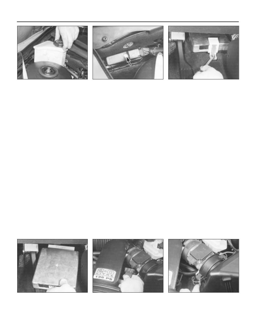
36 Carefully prise the power steering fluid
reservoir upwards out of its clip on the
suspension mounting. Unscrew the ECU
connector’s retaining bolt, and unplug the
connector (see illustrations).
37 Working in the passenger compartment,
unscrew the retaining bolt and withdraw the
mounting bracket (see illustration).
38 Lifting the ECU to release it from the
bulkhead carrier bracket, withdraw the unit
(see illustration).
39 Refitting is the reverse of the removal
procedure. Whenever the ECU (or battery) is
disconnected, the information relating to idle
speed control and other operating values will
be lost from its memory until the unit has re-
programmed itself; until then, there may be
surging, hesitation, erratic idle and a
generally-inferior level of performance. To
allow the ECU to re-learn these values, start
the engine and run it as close to idle speed as
possible until it reaches its normal operating
temperature, then run it for approximately two
minutes at 1200 rpm. Next, drive the vehicle
as far as necessary - approximately 5 miles of
varied driving conditions is usually sufficient -
to complete the re-learning process.
Air mass meter
40 Releasing its wire clip, unplug the meter’s
electrical connector (see illustration).
41 Release the clips and lift the air cleaner
cover, then release the two smaller clips and
detach the meter from the cover (see
illustration).
42 Slacken the clamp securing the meter to
the resonator hose, and withdraw the meter.
43 Refitting is the reverse of the removal
procedure. Ensure that the meter and air
cleaner cover are seated correctly and securely
fastened, so that there are no air leaks.
Crankshaft speed/position sensor
44 Refer to Chapter 5.
Camshaft position sensor
45 Remove the air mass meter and resonator
(refer to Chapter 4) to gain access to the
sensor (see illustration). Release the fuel
feed and return hoses from their clip.
46 Releasing its wire clip, unplug the
sensor’s electrical connector. Remove the
retaining screw, and withdraw the sensor from
the cylinder head; be prepared for slight oil
loss.
47 Refitting is the reverse of the removal
procedure, noting the following points:
6•12 Emissions control systems
4.36A Unclip and lift power steering fluid
reservoir - take care not to spill fluid . . .
4.36B . . . unscrew bolt (arrowed) to
release ECU’s electrical connector
4.37 Unscrew retaining bolt and withdraw
ECU’s mounting bracket . . .
4.40 Unplugging the air mass meter’s
electrical connector . . .
4.38 . . . then lift ECU to disengage it, and
withdraw it
4.41 . . . release clips to separate meter
from air cleaner cover