Ford Mondeo (petrol engines). Manual - part 93
(b) On Estate models, slacken the clamp
immediately above the rear anti-roll bar,
and work the hose off the filler neck stub
(see illustration).
8 Unscrew the six retaining nuts, and
withdraw the exhaust system’s rear heat
shield from the underbody (see illustration).
9 Support the tank with a trolley jack or
similar. Place a sturdy plank between the
support and the tank, to protect the tank.
10 Unscrew the bolt at the front of each
retaining strap, and pivot them down until
they are hanging out of the way. Note the
earth lead under the left-hand strap’s bolt -
clean the mating surfaces before the tank is
refitted, so that clean, metal-to-metal contact
is ensured.
11 Lower the tank enough to unclip the fuel
return pipe (coded red) from its top surface,
then disconnect the charcoal canister’s
vapour hose from the union at the top rear of
the tank (see illustration). If you have any
doubts, clearly label the fuel lines and hoses,
and their respective unions. Plug the hoses, to
prevent leakage and contamination of the fuel
system.
12 Remove the tank from the vehicle,
releasing it from the filler neck stub. While the
tank is removed, unhook the retaining straps
(twist them through 90° to do so), and check
that they and their locations in the underbody
are in good condition.
13 With the fuel tank removed, the filler neck
can be withdrawn. It is secured by a single
screw in the filler opening, and by two bolts to
the underbody.
14 Refitting is the reverse of the removal
procedure.
Warning: Petrol is extremely
flammable, so take extra
precautions when you work on
any part of the fuel system. Don’t
smoke, or allow open flames or bare light
bulbs, near the work area. Don’t work in a
garage where a natural gas-type appliance
(such as a water heater or clothes dryer)
with a pilot light is present. If you spill any
fuel on your skin, rinse it off immediately
with soap and water. When you perform
any kind of work on the fuel system, wear
safety glasses, and have a Class B type
fire extinguisher on hand.
1 Any repairs to the fuel tank or filler neck
should be carried out by a professional who
has experience in this critical and potentially-
dangerous work. Even after cleaning and
flushing of the fuel system, explosive fumes
can remain and ignite during repair of the
tank.
2 If the fuel tank is removed from the vehicle,
it should not be placed in an area where
sparks or open flames could ignite the fumes
coming out of the tank. Be especially careful
inside garages where a natural gas-type
appliance is located, because the pilot light
could cause an explosion.
Warning: The fuel system
pressure must be released before
any part of the system is
disturbed - see Section 2. Petrol
is extremely flammable, so take extra
precautions when you work on any part of
the fuel system. Don’t smoke, or allow
open flames or bare light bulbs, near the
work area. Don’t work in a garage where a
natural gas-type appliance (such as a
water heater or clothes dryer) with a pilot
light is present. If you spill any fuel on your
skin, rinse it off immediately with soap and
water. When you perform any kind of work
on the fuel system, wear safety glasses,
and have a Class B type fire extinguisher
on hand.
Note: Refer to illustrations 10.4 and 10.11 for
details.
1 Remove the fuel tank (see Section 10).
2 Prise the two valves out of the tank, and
remove the anti-trickle fill valve from its
mounting. Take care not to damage the valves
or the tank. Prise out the rubber seals from
the tank openings, and renew then if they are
worn, distorted, or if either has been leaking.
3 If either valve is thought to be faulty, seek
the advice of a Ford dealer as to whether they
can be renewed individually. If not, the
complete valve and pipe assembly must be
renewed.
4 Refitting is the reverse of the removal
procedure. Ensure that both roll-over valves
are pressed securely into their seals, so that
there can be no fuel leaks.
1 Disconnect the battery negative (earth) lead
- see Chapter 5, Section 1.
2 Remove the trim panel from the left-hand
footwell.
3 Peel back the sound-insulating material
from the switch, and undo its two retaining
screws (see illustration).
4 Unplug the switch electrical connector, and
withdraw the switch.
5 Refitting is the reverse of the removal
procedure. Ensure that the switch is reset by
depressing its red button.
These models are equipped with a
Sequential Electronically-controlled Fuel
Injection (SEFI) system. The system is
composed of three basic sub-systems: fuel
system, air induction system and electronic
control system. Note: Refer to illustrations
2.1A and 2.1B of Chapter 6 for further
information on the components of the system.
Fuel system
An electric fuel pump located inside the fuel
tank supplies fuel under pressure to the fuel
rail, which distributes fuel evenly to all
injectors. A filter between the fuel pump and
the fuel rail protects the components of the
system. A pressure regulator controls the
system pressure in relation to inlet tract
depression. From the fuel rail, fuel is injected
14 Fuel injection system/engine
management system - general
information
13 Fuel cut-off switch -
removal and refitting
12 Roll-over valves -
removal and refitting
11 Fuel tank cleaning and repair -
general information
4•8 Fuel and exhaust systems
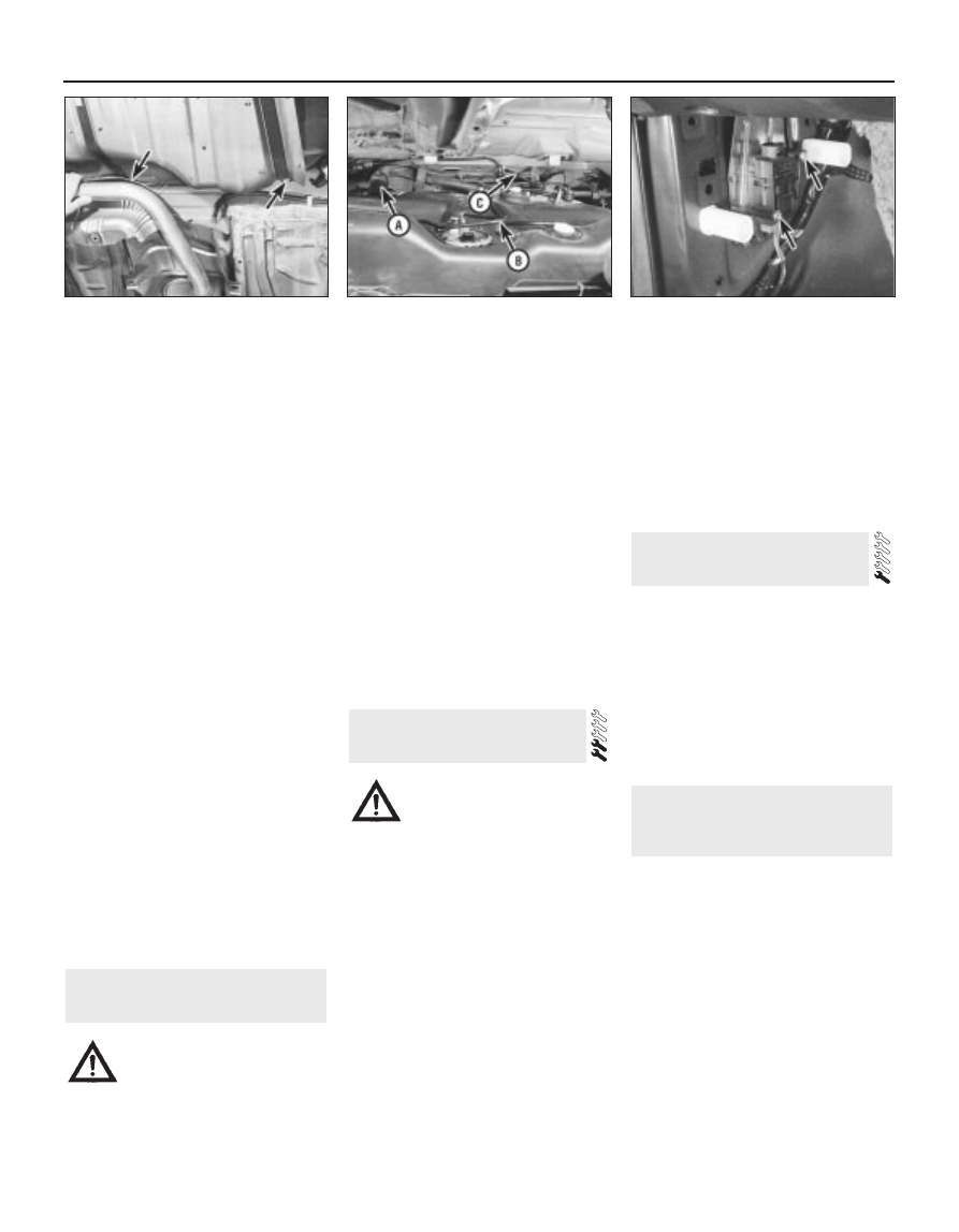
10.8 Exhaust system must be lowered and
heat shield removed to enable fuel tank
removal - arrows show location of
retaining strap front bolts
10.11 Lower fuel tank - do not distort filler
neck stub (A) - and unclip (red-coded) fuel
return pipe (B), then disconnect charcoal
canister’s vapour hose (C)
13.3 Fuel cut-off switch retaining screws
(arrowed)