Ford Mondeo (petrol engines). Manual - part 92
housing stud) and the sealing O-ring in the
chamber’s mouth (see illustrations).
11 Refitting is the reverse of the removal
procedure. Ensure that the O-ring and
spacers are correctly seated.
Underwing components
12 Remove the left-hand wheel arch liner
(see Chapter 11).
13 Unbolt and withdraw the air intake tube
and both resonators as required.
14 Refitting is the reverse of the removal
procedure.
Removal
1 Disconnect the battery negative (earth) lead
- see Chapter 5, Section 1.
2 Remove the plenum chamber (see Sec-
tion 4).
3 Remove the clip securing the cable to the
throttle housing bracket (see illustration).
Disconnect the cable end nipple from the
throttle linkage, and release the cable from
any securing clips or ties.
4 Working in the passenger compartment,
reach up to the top of the accelerator pedal.
Pull the end fitting and collar out of the pedal,
then release the cable inner wire through the
slot in the pedal (see illustration). Tie a length
of string to the end of the cable.
5 Returning to the engine compartment, pull
the cable through the bulkhead until the string
can be untied and the cable removed.
Refitting
6 Refitting is the reverse of the removal
procedure; use the string to draw the cable
through the bulkhead.
7 Adjust the cable as described below.
Adjustment
8 Remove the plenum chamber (see Sec-
tion 4).
9 Find the cable adjuster - this is either at the
throttle housing bracket, or two-thirds along
the length of the cable, clipped to the front
suspension right-hand mounting (see
illustration). Remove the metal clip and
lubricate the adjuster’s grommet with soapy
water.
10 Remove any slack by pulling the cable
outer as far as possible out of the adjuster.
Have an assistant depress the accelerator
pedal fully - the cable outer will move back
into the adjuster - and hold it there while the
clip is refitted.
11 Check that the throttle valve moves
smoothly and easily from the fully-closed to
the fully-open position and back again, as the
assistant depresses and releases the
accelerator pedal. Re-adjust the cable if
required.
12 When the setting is correct, refit the
plenum chamber (see Section 4).
Removal
Note: While the following procedure deals
with the complete cable, the pedal-to-
actuator and actuator-to-throttle housing
sections of the cable are available separately,
and can be removed and refitted individually.
If doing this, modify the procedure as
required.
1 Disconnect the battery negative (earth) lead
- see Chapter 5, Section 1.
2 Remove the plenum chamber (see Sec-
tion 4).
3 Remove the clip securing the cable to the
throttle housing bracket, then pull the cable’s
grommet out of the bracket. Disconnect the
cable end nipple from the throttle linkage, and
release the cable from any securing clips or
ties.
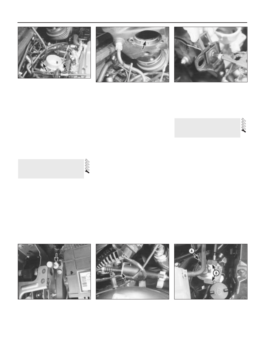
4 Unplug the TCS throttle actuator’s electrical
connector, and prise off its cover (see
illustration).
5 Noting which cable section is connected to
6 Accelerator cable (models
with traction control) -
removal, refitting and adjustment
5 Accelerator cable (models
without traction control) -
removal, refitting and adjustment
4•4 Fuel and exhaust systems
4.10A Lift plenum chamber and (where
fitted) disconnect the vacuum hose - note
the two rubber spacers (arrowed) . . .
4.10B . . . and the sealing O-ring (arrowed)
in the chamber’s mouth
5.3 Removing clip securing accelerator
cable to throttle housing bracket
5.4 Pull the accelerator cable end fitting
(arrowed) out of the pedal
5.9 Location of accelerator cable adjuster
- remove metal clip (arrowed) to enable
adjustment to be made
6.4 Unplug TCS throttle actuator’s
electrical connector (A), and prise off its
cover at two points (B)