Ford Mondeo (petrol engines). Manual - part 35
coolant or EGR pipes, etc. In almost all cases,
damage of this sort is caused in the first
instance by incorrect routing on reassembly
after previous work has been carried out (see
the note at the beginning of this sub-Section).
6 Obviously wires can break or short together
inside the insulation so that no visible
evidence betrays the fault, but this usually
only occurs where the wiring loom has been
incorrectly routed so that it is stretched taut or
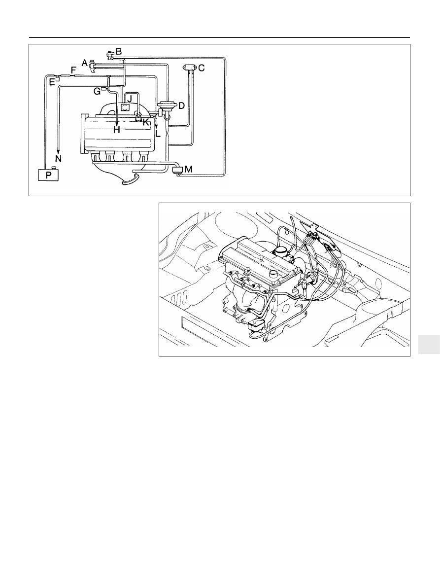
kinked sharply; either of these conditions
should be obvious on even a casual
inspection. If this is thought to have happened
and the fault proves elusive, the suspect
section of wiring should be checked very
carefully during the more detailed checks
which follow.
7 Depending on the extent of the problem,
damaged wiring may be repaired by rejoining
the break or splicing-in a new length of wire,
using solder to ensure a good connection,
and remaking the insulation with adhesive
insulating tape or heat-shrink tubing, as
desired. If the damage is extensive, given the
implications for the vehicle’s future reliability,
the best long-term answer may well be to
renew that entire section of the loom, however
expensive this may appear.
8 When the actual damage has been
repaired, ensure that the wiring loom is
rerouted correctly, so that it is clear of other
components, is not stretched or kinked, and is
secured out of harm’s way using the plastic
clips, guides and ties provided.
9 Check all electrical connectors, ensuring
that they are clean, securely fastened, and
that each is locked by its plastic tabs or wire
clip, as appropriate. If any connector shows
external signs of corrosion (accumulations of
white or green deposits, or streaks of “rust”),
or if any is thought to be dirty, it must be
unplugged and cleaned using electrical
contact cleaner. If the connector pins are
severely corroded, the connector must be
renewed; note that this may mean the renewal
of that entire section of the loom - see your
local Ford dealer for details.
10 If the cleaner completely removes the
corrosion to leave the connector in a
satisfactory condition, it would be wise to
pack the connector with a suitable material
which will exclude dirt and moisture, and
prevent the corrosion from occurring again; a
Ford dealer may be able to recommend a
suitable product. Note:
The system’s
connectors use gold-plated pins, which must
not be mixed with the older tin-plated types
(readily identifiable from the different colour) if
a component is renewed, nor must the lithium
grease previously used to protect tin-plated
pins be used on gold-plated connectors.
11 Following the accompanying schematic
diagram, and working methodically around
the engine compartment, check carefully that
all vacuum hoses and pipes are securely
fastened and correctly routed, with no signs
of cracks, splits or deterioration to cause air
leaks, or of hoses that are trapped, kinked, or
bent sharply enough to restrict air flow (see
illustrations). Check with particular care at all
connections and sharp bends, and renew any
damaged or deformed lengths of hose.
12 Working from the fuel tank, via the filter, to
the fuel rail (and including the feed and return),
check the fuel lines, and renew any that are
found to be leaking, trapped or kinked.
13 Check that the accelerator cable is
correctly secured and adjusted; renew the
cable if there is any doubt about its condition,
or if it appears to be stiff or jerky in operation.
Refer to the relevant Sections of Chapter 4 for
further information, if required.
14 If there is any doubt about the operation
of the throttle, remove the plenum chamber
from the throttle housing, and check that the
throttle valve moves smoothly and easily from
the fully-closed to the fully-open position and
Emissions control systems 6•5
6
3.11A Vacuum hose routing schematic diagram
A Exhaust Gas Recirculation (EGR) solenoid valve
B Pulse-air solenoid valve
C Exhaust Gas Recirculation (EGR) exhaust gas pressure
differential sensor
D Exhaust Gas Recirculation (EGR) valve
E Charcoal canister-purge solenoid valve
F Restrictor
G Idle-increase solenoid valve - where fitted
H Connection to plenum chamber
J Connection to inlet manifold
K Fuel pressure regulator
L Connection to Positive Crankcase Ventilation (PCV) valve
M Pulse-air filter housing
N Connection to heating/air conditioning system controls
P Charcoal canister
3.11B Installation of vacuum hoses in engine compartment