Ford Mondeo (petrol engines). Manual - part 34
 

  Index      Ford     Ford Mondeo - service and repair manual (petrol engines)


Search            


Content   ..  32  33  34  35   ..


Ford Mondeo (petrol engines). Manual - part 34


Chapter 6 Emissions control systems

Catalytic converter - general information, checking 

and component renewal  . . . . . . . . . . . . . . . . . . . . . . . . . . . . . . . .

9

Diagnosis system - general information  . . . . . . . . . . . . . . . . . . . . . .

3

Electronic control system - description and precautions  . . . . . . . . .

2

Engine compartment wiring check  . . . . . . . . . . . . . . .

See Chapter 1

EVAPorative emissions control (EVAP) system - general 

information, checking and component renewal  . . . . . . . . . . . . . .

5

Exhaust Gas Recirculation (EGR) system - general 

information, checking and component renewal  . . . . . . . . . . . . . .

6

Exhaust system check  . . . . . . . . . . . . . . . . . . . . . . . . .

See Chapter 1

General information . . . . . . . . . . . . . . . . . . . . . . . . . . . . . . . . . . . . . .

1

Information sensors - general information, testing, 

removal and refitting  . . . . . . . . . . . . . . . . . . . . . . . . . . . . . . . . . . .

4

Positive Crankcase Ventilation (PCV) system - general 

information, checking and component renewal  . . . . . . . . . . . . . .

8

Positive Crankcase Ventilation (PCV) system check 
and filter cleaning . . . . . . . . . . . . . . . . . . . . . . . . . . . . .

See Chapter 1

Pulse-air system - general information, checking 

and component renewal  . . . . . . . . . . . . . . . . . . . . . . . . . . . . . . . .

7

Underbonnet hose check . . . . . . . . . . . . . . . . . . . . . . .

See Chapter 1

Crankshaft speed/position sensor

Resistance . . . . . . . . . . . . . . . . . . . . . . . . . . . . . . . . . . . . . . . . . . . . . . . .

200 to 450 ohms

Camshaft position sensor

Resistance . . . . . . . . . . . . . . . . . . . . . . . . . . . . . . . . . . . . . . . . . . . . . . . .

200 to 900 ohms

Intake air temperature sensor

Resistance:

At -40°C . . . . . . . . . . . . . . . . . . . . . . . . . . . . . . . . . . . . . . . . . . . . . . . .

860 to 900 k ohms

At 20°C  . . . . . . . . . . . . . . . . . . . . . . . . . . . . . . . . . . . . . . . . . . . . . . . .

35 to 40 k ohms

At 100°C  . . . . . . . . . . . . . . . . . . . . . . . . . . . . . . . . . . . . . . . . . . . . . . .

1.9 to 2.5 k ohms

At 120°C  . . . . . . . . . . . . . . . . . . . . . . . . . . . . . . . . . . . . . . . . . . . . . . .

1.0 to 1.3 k ohms

Throttle potentiometer

Resistance - see text  . . . . . . . . . . . . . . . . . . . . . . . . . . . . . . . . . . . . . . .

400 to 6000 ohms

Power steering pressure switch

Operating pressure - green switch  body:

Contacts open - infinite  resistance  . . . . . . . . . . . . . . . . . . . . . . . . . .

31.5 ± 3.5 bars

Contacts close - 0 to 2.5 ohms  resistance  . . . . . . . . . . . . . . . . . . . .

Between 13.5 and 24.0 bars

Charcoal canister-purge solenoid valve

Resistance . . . . . . . . . . . . . . . . . . . . . . . . . . . . . . . . . . . . . . . . . . . . . . . .

50 to 120 ohms

Pulse-air solenoid valve

Resistance . . . . . . . . . . . . . . . . . . . . . . . . . . . . . . . . . . . . . . . . . . . . . . . .

50 to 120 ohms

Torque wrench settings

Nm

lbf ft

Camshaft position sensor screw . . . . . . . . . . . . . . . . . . . . . . . . . . . . . . .

18 to 23

13 to 17

Intake air temperature sensor  . . . . . . . . . . . . . . . . . . . . . . . . . . . . . . . . .

23

17

Oxygen sensor  . . . . . . . . . . . . . . . . . . . . . . . . . . . . . . . . . . . . . . . . . . . .

60

44

Exhaust Gas Recirculation (EGR)  system components:

Valve-to-inlet manifold bolts  . . . . . . . . . . . . . . . . . . . . . . . . . . . . . . . .

9

6

Pipe-to-ignition coil screws . . . . . . . . . . . . . . . . . . . . . . . . . . . . . . . . .

10

7

Pulse-air system components:

Filter housing mounting bolt  . . . . . . . . . . . . . . . . . . . . . . . . . . . . . . . .

47

35

Piping-to-exhaust manifold  sleeve nuts . . . . . . . . . . . . . . . . . . . . . . .

32

24

6•1

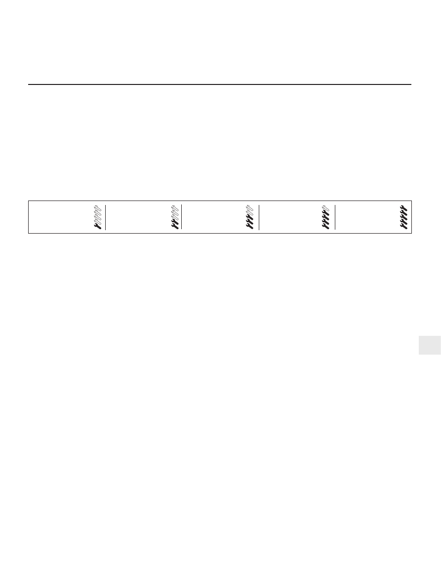
Easy, suitable for
novice with little
experience

Fairly easy, suitable
for beginner with
some experience

Fairly difficult, suitable
for competent DIY
mechanic

Difficult, suitable for
experienced  DIY
mechanic

Very difficult,
suitable for expert DIY
or  professional

Degrees of difficulty

Specifications

Contents

6

To minimise pollution of the atmosphere

from incompletely-burned and evaporating
gases, and to maintain good driveability and
fuel economy, a number of emission control
systems are used on these vehicles. They
include the following:
(a) The engine management system

(comprising both fuel and ignition sub-
systems) itself.

(b) Positive Crankcase Ventilation (PCV)

system.

(c) Evaporative Emissions Control (EVAP)

system.

(d) Exhaust Gas Recirculation (EGR) system.
(e) Catalytic converter.

The Sections of this Chapter include

general descriptions, checking procedures
within the scope of the home mechanic, and
component renewal procedures (when
possible) for each of the systems listed above.

Before assuming an emissions control system

is malfunctioning, check the fuel and ignition
systems carefully (see Chapters 4 and 5). The
diagnosis of some emission control devices
requires specialised tools, equipment and
training. If checking and servicing become too
difficult, or if a procedure is beyond the scope of

your skills, consult your dealer service
department or other specialist.

This doesn’t mean, however, that emission

control systems are particularly difficult to
maintain and repair. You can quickly and
easily perform many checks, and do most of
the regular maintenance, at home with
common tune-up and hand tools. Note: The
most frequent cause of emissions problems is
simply a loose or broken electrical connector
or vacuum hose, so always check the
electrical connectors and vacuum hoses first.

Pay close attention to any special

precautions outlined in this Chapter. It should
be noted that the illustrations of the various
systems may not exactly match the system
installed on your vehicle, due to changes
made by the manufacturer during production
or from year-to-year.

Vehicles sold in some areas will carry a

Vehicle Emissions Control Information (VECI)
label, and a vacuum hose diagram located in
the engine compartment. These contain
important specifications and setting
procedures for the various emissions control
systems, with the vacuum hose diagram
identifying emissions control components.
When servicing the engine or emissions
systems, the VECI label in your particular
vehicle should always be checked for up-to-
date information.

Description

The EEC-IV (Ford’s fourth-generation

Electronic Engine Control system) engine
management system controls fuel injection by
means of a microcomputer known as the ECU
(Electronic Control Unit) (see illustrations).

The ECU receives signals from various

sensors, which monitor changing engine
operating conditions such as intake air mass
(ie, intake air volume and temperature),
coolant temperature, engine speed,
acceleration/deceleration, exhaust oxygen
content, etc. These signals are used by the
ECU to determine the correct injection
duration.

The system is analogous to the central

nervous system in the human body - the
sensors (nerve endings) constantly relay
signals to the ECU (brain), which processes
the data and, if necessary, sends out a
command to change the operating
parameters of the engine (body) by means of
the actuators (muscles).

Here’s a specific example of how one

portion of this system operates. An oxygen
sensor, located in the exhaust downpipe,

2 Electronic control system -

description and precautions

1 General information

6•2 Emissions control systems

Emissions control systems  6•3

6

2.1B  Location of principal fuel injection, ignition and

emissions control system components

2.1A  Engine management system, showing fuel injection, 

ignition and emissions control sub-systems

1  ECU (Electronic Control Unit)
2  Fuel pump/fuel gauge sender

unit

3  Fuel pump relay
4  Fuel filter
5  Idle speed control valve
6  Air mass meter
7  Air cleaner assembly
8  Fuel pressure regulator
9  Fuel rail

10  Throttle potentiometer
11  Intake air temperature sensor
12  Fuel injector
13  Camshaft position sensor
14  Charcoal canister
15  Charcoal canister-purge

solenoid valve

16  Ignition coil
17  Battery
18  Ignition module - only

separate (from ECU) on
vehicles with automatic
transmission

19  Coolant temperature sensor
20  Oxygen sensor
21  Crankshaft speed/position

sensor

22  Power supply relay
23  Power steering pressure

switch

24  Air conditioning compressor

clutch solenoid

25  Service connector - for octane

adjustment

26  Self-test connector - for Ford

STAR tester diagnostic
equipment

27  Diagnosis connector - for Ford

diagnostic equipment FDS
2000

28  Ignition switch
29  Fuel cut-off switch
30  Exhaust Gas Recirculation

(EGR) solenoid valve

31  Exhaust Gas Recirculation

(EGR) valve

32  Exhaust Gas Recirculation

(EGR) exhaust gas pressure
differential sensor

33  Exhaust Gas Recirculation

(EGR) pressure differential
measuring point

34  To inlet manifold
35  Pulse-air filter housing
36  Pulse-air solenoid valve
37  Air conditioning/radiator

electric cooling fan control

38  Automatic transmission

control system - where
applicable

1  ECU (Electronic Control Unit)
2  Self-test, diagnosis and service connectors 

(left to right)

3  Bulkhead component mounting bracket - manual

transmission - showing from left to right, (EGR) solenoid
valve, pulse-air solenoid valve and (EGR) exhaust gas
pressure differential sensor

4  Bulkhead component mounting bracket - automatic

transmission - showing from left to right, (EGR) solenoid
valve, pulse-air solenoid valve and (EGR) exhaust gas
pressure differential sensor, with separate ignition module
above

5  Throttle housing, including potentiometer
6  Idle speed control valve
7  Intake air temperature sensor
8  Air mass meter
9  Exhaust Gas Recirculation (EGR) valve

10  Coolant temperature sensor
11  Crankshaft speed/position sensor
12  Pulse-air filter housing
13  Oxygen sensor
14  Ignition coil and spark plug (HT) leads
15  Camshaft position sensor
16  Fuel injector(s)
17  Power steering pressure switch
18  Air cleaner assembly
19  Air intake tube and resonators - under left-hand front wing
20  Resonator

constantly monitors the oxygen content of the
exhaust gas. If the percentage of oxygen in
the exhaust gas is incorrect, an electrical
signal is sent to the ECU. The ECU processes
this information, and then sends a command
to the fuel injection system, telling it to change
the air/fuel mixture; the end result is an air/fuel
mixture ratio which is constantly maintained
at a predetermined ratio, regardless of driving
conditions. This happens in a fraction of a
second, and goes on almost all the time while
the engine is running - the exceptions are that
the ECU cuts out the system and runs the
engine on values pre-programmed
(“mapped”) into its memory both while the
oxygen sensor is reaching its normal
operating temperature after the engine has
been started from cold, and when the throttle
is fully open for full acceleration.

In the event of a sensor malfunction, a

back-up circuit will take over, to provide
driveability until the problem is identified and
fixed.

Precautions

(a) Always disconnect the power by

uncoupling the battery terminals - see
Section 1 of Chapter 5 - before removing
any of the electronic control system’s
electrical connectors.

(b) When installing a battery, be particularly

careful to avoid reversing the positive and
negative battery leads.

(c) Do not subject any components of the

system (especially the ECU)  to severe
impact during removal or installation.

(d) Do not be careless during fault diagnosis.

Even slight terminal contact can invalidate
a testing procedure, and damage one of
the numerous transistor circuits.

(e) Never attempt to work on the ECU, to test

it (with any kind of test equipment), or to
open its cover.

(f)

If you are inspecting electronic control
system components during rainy weather,
make sure that water does not enter any
part. When washing the engine
compartment, do not spray these parts or
their electrical connectors with water.

General

The various components of the fuel, ignition

and emissions control systems (not forgetting
the same ECU’s control of sub-systems such
as the radiator cooling fan, air conditioning
and automatic transmission, where
appropriate) are so closely interlinked that
diagnosis of a fault in any one component is
virtually impossible using traditional methods.
Working on simpler systems in the past, the
experienced mechanic may well have been
able to use personal skill and knowledge
immediately to pinpoint the cause of a fault, or
quickly to isolate the fault, by elimination;

however, with an engine management system
integrated to this degree, this is not likely to
be possible in most instances, because of the
number of symptoms that could arise from
even a minor fault.

So that the causes of faults can be quickly

and accurately traced and rectified, the ECU
is provided with a built-in self-diagnosis
facility, which detects malfunctions in the
system’s components. When a fault occurs,
three things happen: the ECU identifies the
fault, stores a corresponding code in its
memory, and (in most cases) runs the system
using back-up values pre-programmed
(“mapped”) into its memory; some form of
driveability is thus maintained, to enable the
vehicle to be driven to a garage for attention.

Any faults that may have occurred are

indicated in the form of three-digit codes
when the system is connected (via the built-in
diagnosis or self-test connectors, as
appropriate) to special diagnostic equipment -
this points the user in the direction of the
faulty circuit, so that further tests can pinpoint
the exact location of the fault.

Given below is the procedure that would be

followed by a Ford technician to trace a fault
from scratch. Should your vehicle’s engine
management system develop a fault, read
through the procedure and decide how much
you can attempt, depending on your skill and
experience and the equipment available to
you, or whether it would be simpler to have
the vehicle attended to by your local Ford
dealer. If you are concerned about the
apparent complexity of the system, however,
remember the comments made in the fourth
paragraph of Section 1 of this Chapter; the
preliminary checks require nothing but care,
patience and a few minor items of equipment,
and may well eliminate the majority of faults.
(a) Preliminary checks
(b) Fault code read-out *
(c) Check ignition timing and base idle

speed. Recheck fault codes to establish
whether fault has been cured or not *

(d) Carry out basic check of ignition system

components. Recheck fault codes to
establish whether fault has been cured or
not *

(e) Carry out basic check of fuel system

components. Recheck fault codes to
establish whether fault has been cured or
not *

(f)

If fault is still not located, carry out system
test *

Note: Operations marked with an asterisk
require special test equipment.

Preliminary checks

Note: When carrying out these checks to
trace a fault, remember that if the fault has
appeared only a short time after any part of
the vehicle has been serviced or overhauled,
the first place to check is where that work was
carried out, however unrelated it may appear,
to ensure that no carelessly-refitted
components are causing the problem.

If you are tracing the cause of a “partial”

engine fault, such as lack of performance, in
addition to the checks outlined below, check
the compression pressures (see Part A of
Chapter 2) and bear in mind the possibility
that one of the hydraulic tappets might be
faulty, producing an incorrect valve clearance.
Check also that the fuel filter has been
renewed at the recommended intervals.

If the system appears completely dead,

remember the possibility that the
alarm/inhibitor system may be responsible.
The first check for anyone without special
test equipment is to switch on the ignition,
and to listen for the fuel pump (the sound of
an electric motor running, audible from
beneath the rear seats); assuming there is
sufficient fuel in the tank, the pump should
start and run for approximately one or two
seconds, then stop, each time the ignition is
switched on. If the pump runs continuously all
the time the ignition is switched on, the
electronic control system is running in the
back-up (or “limp-home”) mode referred to by
Ford as “Limited Operation Strategy” (LOS).
This almost certainly indicates a fault in the
ECU itself, and the vehicle should therefore be
taken to a Ford dealer for a full test of the
complete system using the correct diagnostic
equipment; do not waste time trying to test
the system without such facilities.
If the fuel pump is working correctly (or not
at all), a considerable amount of fault
diagnosis is still possible without special test
equipment. Start the checking procedure as
follows.
Open the bonnet and check the condition
of the battery connections - remake the
connections or renew the leads if a fault is
found (Chapter 5). Use the same techniques
to ensure that all earth points in the engine
compartment provide good electrical contact
through clean, metal-to-metal joints, and that
all are securely fastened. (In addition to the
earth connection at the engine lifting eye and
that from the transmission to the
body/battery, there is one earth connection
behind each headlight assembly, and one
below the power steering fluid reservoir.)
Referring to the information given in
Chapter 12 and in the wiring diagrams at the
back of this manual, check that all fuses
protecting the circuits related to the engine
management system are in good condition.
Fit new fuses if required; while you are there,
check that all relays are securely plugged into
their sockets.
Next work methodically around the engine
compartment, checking all visible wiring, and
the connections between sections of the
wiring loom. What you are looking for at this
stage is wiring that is obviously damaged by
chafing against sharp edges, or against
moving suspension/transmission components
and/or the auxiliary drivebelt, by being
trapped or crushed between carelessly-
refitted components, or melted by being
forced into contact with hot engine castings,

3 Diagnosis system 

general information

6•4 Emissions control systems


Content   ..  32  33  34  35   ..